⦿ A computerinstruction is a group of bits that
instructs the computer to perform a particular task.
⦿ Each instruction cycle is subdivided into different
parts.
⦿ This lecture explains about phases of
instruction cycle in detail.
3.
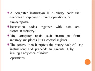
⦿ A computerinstruction is a binary code that
specifies a sequence of micro operations for
the computer.
⦿ Instruction codes together with data are
stored in memory.
⦿ The computer reads each instruction from
memory and places it in a control register.
⦿ The control then interprets the binary code of the
instructions and proceeds to execute it by
issuing a sequence of micro
operations.
4.
⦿ The instructioncycle (also known as the
fetch–decode–execute cycle, or simply the
fetch-execute cycle) is the cycle that the central
processing unit (CPU) follows from boot-up until
the computer has shut down in order to process
instructions.
6.
⦿ ´A programconsisting of sequence of instructions is
executed in the computer by going through a cycle
for each instruction.
⦿ ´ Each instruction cycle is subdivided in to sub cycles
or phases.They are
´Fetch an instruction from memory
´Decode instruction
´Read effective address from memory if instruction
has an indirect address
´Execute instruction
⦿ This cycle repeats indefinitely unless a HALT
instruction is encountered
7.
⦿ The basiccomputer has three instruction code
formats.
⦿ Each format has 16 bits.
⦿ The operation code (opcode) part of the instruction
contains three bits and the meaning of the remaining
13 bits depends on the operation code encountered.
8.
⦿ A memoryreferenceinstruction uses 12 bits
to specify an address and one bit to specify
the addressing mode I.
⦿ I is equal to 0 for direct address and to 1 for
indirect address
11.
⦿ ´Initially PCis loaded with the address of
the first instruction in the program
⦿ ´SC is cleared to 0 providing a decoded
timing
signal T0 .
⦿ ´SC is incremented to 1 so that timing signals go
through T0 through T15
⦿ At T0Transfers the address from PC to AR
⦿ ´At T1 Instruction read from memory is
placed in IR and PC is incremented by 1 to
get the address of next instruction
⦿ ´ At T2 opcode in IR is decoded , Indirect bit is
transferred to flipflop I & address part is
transferred to AR
⦿ ´After decoding next step is to determine
the type of instruction
14.
After decoding timingsignal active is T3
during which instruction type is identified
´Memory Reference
If D7=0 opcode will be 000 through 110
If D7=0 and I=1,indirect and
D7=0 and I=0 direct
Microoperations for indirect address
should be initially AR←M[AR]
´Register reference/ io
If D7=1 and I=0 -
Register If D7=1 and I=1 –
i/o
15.
Decoder output D7is equal to 1 if the operation code
is equal to binary 111.
We determine that if D1 = 1, the instruction must
be a register-reference or input-output type.
If D7 = 0, the operation code must be one of the
other seven values 000 through 110, specifying
memory reference instruction.
Control then inspects the value of the first bit of the
instruction, which is
now available in flip-flop I
16.
If D7 =0 and I = 1, we have a memory-
reference instruction with an
indirect address.
It is then necessary to read the effective
address from memory.
The microoperation for the indirect address
condition can be symbolized by the register
transfer statement
AR ← M [AR]
17.
The 3 instructionssubdivided into 4 paths
⦿ D7’IT3:AR←M[AR] (Mem reference and
indirect)
⦿ D7’I’T3:Nothing(Mem reference and
direct)
⦿ D7I’T3: Execute register reference
⦿ D7IT3:Execute io instruction
18.
When a memory-referenceinstruction with I = 0 is
encountered, it is not necessary to do anything since
the effective address is already in AR.
However, the sequence counter SC must be
incremented when D’7 T3 = 1, so that the
execution of the memory-reference instruction can
be continued with timing variable T4.
19.
A register-reference orinput-output instruction
can be executed with the clock associated with
timing signal T3.
After the instruction is executed, SC is cleared to
0 and control returns to the fetch phase with T0 =
1.
20.
The timing signalthat is active after the
decoding is T3.
During time T3, the control unit determines the
type of instruction that was just read from
memory.
The following flowchart presents an initial
configuration for the instruction cycle and
shows how the control determines the
instruction type after the decoding.
22.
Note that thesequence counter SC is either
incremented or cleared to 0 with every
positive clock transition.
We will adopt the convention that if SC is
incremented, we will not write the statement SC ←
SC + 1, but it will be implied that the control
goes to the next timing
signal in sequence.
When SC is to be cleared, we will include the
statement Sc ← 0


![FOR FETCH
AND DECODE
The
microoperations
phases are
⦿ T0:AR←PC
⦿ T1:IR←M[AR] ,
PC<- PC+1
⦿ T2:D0,D1..D7←Decode IR(12-14),
AR←IR(0- 11), I←IR(15)](https://image.slidesharecdn.com/intcycleppt-250829163944-ca7bc345/85/int-cycle-ppt-instructions-cycle-computer-12-320.jpg)

![After decoding timing signal active is T3
during which instruction type is identified
´Memory Reference
If D7=0 opcode will be 000 through 110
If D7=0 and I=1,indirect and
D7=0 and I=0 direct
Microoperations for indirect address
should be initially AR←M[AR]
´Register reference/ io
If D7=1 and I=0 -
Register If D7=1 and I=1 –
i/o](https://image.slidesharecdn.com/intcycleppt-250829163944-ca7bc345/85/int-cycle-ppt-instructions-cycle-computer-14-320.jpg)

![If D7 = 0 and I = 1, we have a memory-
reference instruction with an
indirect address.
It is then necessary to read the effective
address from memory.
The microoperation for the indirect address
condition can be symbolized by the register
transfer statement
AR ← M [AR]](https://image.slidesharecdn.com/intcycleppt-250829163944-ca7bc345/85/int-cycle-ppt-instructions-cycle-computer-16-320.jpg)
![The 3 instructions subdivided into 4 paths
⦿ D7’IT3:AR←M[AR] (Mem reference and
indirect)
⦿ D7’I’T3:Nothing(Mem reference and
direct)
⦿ D7I’T3: Execute register reference
⦿ D7IT3:Execute io instruction](https://image.slidesharecdn.com/intcycleppt-250829163944-ca7bc345/85/int-cycle-ppt-instructions-cycle-computer-17-320.jpg)