Downloaded 260 times
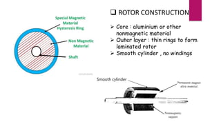

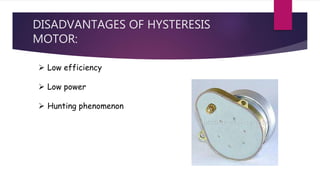


The document details the design and operation of hysteresis motors, which are synchronous motors without direct current excitation that can be powered by single or three-phase supplies. It explains the construction of the stator and rotor, the behavior of magnetic domains during operation, and the relationship between torque and speed, highlighting the characteristics and applications of hysteresis motors. Advantages include smooth operation and low noise, while disadvantages are low efficiency and power.


