This document proposes a new fuzzy logic-based routing protocol for mobile ad-hoc networks (MANETs) that considers path stability, residual energy of nodes, and bandwidth for optimal path selection at the source node. It also proposes adjusting the transmission rate at the source node based on end-to-end delay and packet loss ratio measured at the destination node. This cross-layer approach uses two fuzzy logic systems - one for path selection based on stability and bandwidth, and another for transmission rate adjustment based on delay and packet loss. The goal is to select stable paths and prevent congestion for more efficient data transmission in MANETs.
![International Journal of Networks (IJN)
Vol. 1, Issue. 1, April – 2015 ISSN (Online): 2454-1060
1
Abstract—In mobile ad-hoc network, the performance depends
on the adaptability of the underlying routing protocol to current
network condition. The existing fuzzy based cross layer routing
protocol in which the parameters such as number of hops and
mobile speed for estimating link stability in the network has the
drawback of leading to overhead and dependency. In turn
leading to delay and inefficiency in data transmission. In order to
overcome these drawbacks, in this paper we propose fuzzy based
optimal path selection by considering the path stability, the
residual energy of the nodes and bandwidth as parameters at the
source node. The path stability is estimated based on available
battery power, distance and link quality. The residual energy is
estimated for the node at both the situations, when the node
receives and transmits the data packets. Following the path
selection, fuzzy based transmission rate adjustment of source is
calculated by considering end to end delay and packet loss ratio
as parameters at destination node. Also we propose a method to
draw a table, which includes energy efficiency in all combination
of transmission power and rate, is updated by each node.
Index Terms—Ad-Hoc On Demand Distance Vector Routing
protocol (AODV), Fuzzy inference system, Cross-Layer design.
I. INTRODUCTION
I.1. MOBILE AD-HOC NETWORK (MANET)
With the extensive growth of wireless handheld devices
and plummeting costs [1] has emerged as a major area of
research for both academics and the industrial sector. A
Mobile network is a set of mobile telecommunications, Mobile
Ad-hoc Network (MANET) of wireless mobile nodes which
are infrastructure-less network consisting of numbers of mobile
hosts’ communication with one another through multiple hop
wireless links. MANETs are self-organizing, self-configuring
and dynamic topology network making them convenient for
combat, medical and other emergency situations.
I.2. ROUTING PROTOCOL
The MANETS’s routing protocol finds routes between
nodes and then allows data packets to be forwarded through
other network nodes towards the final destination [2].
The routing protocol for MANET could be broadly
classified into two major categories based on the method of
keeping the information about routes in the network.
They are:
Proactive Routing Protocol
Reactive Routing Protocol
I.3. AD-HOC ON DEMAND DISTANCE VECTOR ROUTING
PROTOCOL (AODV)
Ad-hoc On-demand Distance Vector (AODV) [2] routing
protocol is one of the MANET routing protocols which comes
classified under reactive protocol. It provides efficient route
establishment between nodes in a wireless network
communication between mobile nodes with minimal control
overhead and minimal route acquisition latency. The two main
operations taking place in AODV protocol are Route
discovery and Route maintenance.
I.4. FUZZY INFERENCE SYSTEM
Fuzzy Inference System [3] is a system that uses fuzzy
logic to map a set of inputs to a set of outputs.
Fuzzy Logic was initiated to represent /manipulate data
possessing non-statistical uncertainties. Fuzzy logic is a multi-
valued logic which deals with reasoning that are approximate
rather than fixed and exact. Fuzzy logic variables may have
truth value that ranges on degree between 0 and 1. It has been
extended to handle the concept of partial truth and hence the
truth value ranges from completely true to completely false.
Fuzzy logic provides inference morphology and enables
approximate human reasoning capabilities to be applied to be
applied to knowledge based system.
The fuzzy logic provides mathematical strength to capture
the uncertainties associated with human cognitive process such
as thinking and reasoning
I.5. CROSS LAYER DESIGN
In Ad-Hoc network, each and every node communicates
with each other through the OSI layer. But the defect of this
reference protocol architecture is that adjacent layers only can
communicate with each other and every layer has its own
Cross- Layer based efficient data transmission in MANET
using Fuzzy Logic
1
Narayanan.S, 2
Rani Thottungal, 3
R.Aarthi, 4
M.Nija Priya, 5
M.Anu
1
Department of Information Technology,Valliammai Engineering College, Chennai, India.
2
Department Of EEE Kumaraguru College of EngIneering, Coimbatore, India
3,4,5
UG Scholar, Valliammai Engineering College, Chennai, India](https://image.slidesharecdn.com/iisrtaarthiravindrannetworks-150705081002-lva1-app6892/85/Iisrt-aarthi-ravindran-networks-1-320.jpg)
![International Journal of Networks (IJN)
Vol. 1, Issue. 1, April – 2015 ISSN (Online): 2454-1060
1
Abstract—In mobile ad-hoc network, the performance depends
on the adaptability of the underlying routing protocol to current
network condition. The existing fuzzy based cross layer routing
protocol in which the parameters such as number of hops and
mobile speed for estimating link stability in the network has the
drawback of leading to overhead and dependency. In turn
leading to delay and inefficiency in data transmission. In order to
overcome these drawbacks, in this paper we propose fuzzy based
optimal path selection by considering the path stability, the
residual energy of the nodes and bandwidth as parameters at the
source node. The path stability is estimated based on available
battery power, distance and link quality. The residual energy is
estimated for the node at both the situations, when the node
receives and transmits the data packets. Following the path
selection, fuzzy based transmission rate adjustment of source is
calculated by considering end to end delay and packet loss ratio
as parameters at destination node. Also we propose a method to
draw a table, which includes energy efficiency in all combination
of transmission power and rate, is updated by each node.
Index Terms—Ad-Hoc On Demand Distance Vector Routing
protocol (AODV), Fuzzy inference system, Cross-Layer design.
I. INTRODUCTION
I.1. MOBILE AD-HOC NETWORK (MANET)
With the extensive growth of wireless handheld devices
and plummeting costs [1] has emerged as a major area of
research for both academics and the industrial sector. A
Mobile network is a set of mobile telecommunications, Mobile
Ad-hoc Network (MANET) of wireless mobile nodes which
are infrastructure-less network consisting of numbers of mobile
hosts’ communication with one another through multiple hop
wireless links. MANETs are self-organizing, self-configuring
and dynamic topology network making them convenient for
combat, medical and other emergency situations.
I.2. ROUTING PROTOCOL
The MANETS’s routing protocol finds routes between
nodes and then allows data packets to be forwarded through
other network nodes towards the final destination [2].
The routing protocol for MANET could be broadly
classified into two major categories based on the method of
keeping the information about routes in the network.
They are:
Proactive Routing Protocol
Reactive Routing Protocol
I.3. AD-HOC ON DEMAND DISTANCE VECTOR ROUTING
PROTOCOL (AODV)
Ad-hoc On-demand Distance Vector (AODV) [2] routing
protocol is one of the MANET routing protocols which comes
classified under reactive protocol. It provides efficient route
establishment between nodes in a wireless network
communication between mobile nodes with minimal control
overhead and minimal route acquisition latency. The two main
operations taking place in AODV protocol are Route
discovery and Route maintenance.
I.4. FUZZY INFERENCE SYSTEM
Fuzzy Inference System [3] is a system that uses fuzzy
logic to map a set of inputs to a set of outputs.
Fuzzy Logic was initiated to represent /manipulate data
possessing non-statistical uncertainties. Fuzzy logic is a multi-
valued logic which deals with reasoning that are approximate
rather than fixed and exact. Fuzzy logic variables may have
truth value that ranges on degree between 0 and 1. It has been
extended to handle the concept of partial truth and hence the
truth value ranges from completely true to completely false.
Fuzzy logic provides inference morphology and enables
approximate human reasoning capabilities to be applied to be
applied to knowledge based system.
The fuzzy logic provides mathematical strength to capture
the uncertainties associated with human cognitive process such
as thinking and reasoning
I.5. CROSS LAYER DESIGN
In Ad-Hoc network, each and every node communicates
with each other through the OSI layer. But the defect of this
reference protocol architecture is that adjacent layers only can
communicate with each other and every layer has its own
Cross- Layer based efficient data transmission in MANET
using Fuzzy Logic
1
Narayanan.S, 2
Rani Thottungal, 3
R.Aarthi, 4
M.Nija Priya, 5
M.Anu
1
Department of Information Technology,Valliammai Engineering College, Chennai, India.
2
Department Of EEE Kumaraguru College of EngIneering, Coimbatore, India
3,4,5
UG Scholar, Valliammai Engineering College, Chennai, India](https://image.slidesharecdn.com/iisrtaarthiravindrannetworks-150705081002-lva1-app6892/75/Iisrt-aarthi-ravindran-networks-1-2048.jpg)
![International Journal of Networks (IJN)
Vol. 1, Issue. 1, April – 2015 ISSN (Online): 2454-1060
2
information which cannot be accessed by other layers. Cross-
layer design [4] is the protocol design which is mainly used to
remove the dependency between layers .Cross layer is the
interface that is used for sharing information between layers. It
is mainly used to enhance the performance of a system. In this
paper, we have used shared database design of the cross layer.
II. RELATED WORK
Siddesh Gundagatti Karibasappa et al. [5] proposed neuro
fuzzy based routing protocol. They have utilized the soft
computing techniques such as Neural Nets, Fuzzy Logic and
genetic Algorithms to derive accurate routing information from
mobile Ad-Hoc networks to achieve this efficient protocol. To
solve the objective function and establish a route within the
shortest possible time the combination of these powerful
techniques are used. This protocol has used feed forward
artificial neural network to achieve best performance in
routing.
M.Niazi Torshiz et al. [6] proposed to incorporate the fuzzy
concept with AODV routing algorithm and have considered
power consumption. This fuzzy logic based routing algorithm
monitors the routes and tries to select the optimal route based
on minimum bandwidth and hop count of each route. It also
has tried to balance the traffic load inside the network so as to
increase the battery lifetime of the nodes and hence the overall
useful life of the ad hoc network. In this paper, the fuzzy input
variables are chosen to be minimum bandwidth, battery life
and hop-count.
Zuo Jing et al. [7] proposed a multi constrained QoS
routing protocol based on fuzzy logic. The protocol is service
aware and developed based on DSR. It has considered the QoS
requirements asked by different kinds of services and takes
different network state parameters as the constraint conditions.
They proposed new route informing mechanism to support
route update; and have adjusted the speed of packet in terms of
the output of fuzzy system; also they have optimized routing
algorithm for real time traffic to assure that data are always
transmitted through the route with the lowest delay. In this
proposal, the fuzzy system consists of three subsystems.
Therefore multiple metrics have been considered as fuzzy
inputs. The fuzzy inputs used are number of hops, bandwidth,
mobile speed and buffer occupancy rate.
Golnoosh Ghalavani et al. [8] proposed a reliable routing
protocol for MANET based on fuzzy logic. The proposed
work is known as RRAF and it finds reliable path for the
transmission of data. In their work, during route discovery,
node with maximum trust value and maximum energy
capacity is selected as a router based on a parameter called
“Reliability Value”. Battery power and trust value of
individual nodes are used to find the reliable path. This
approach forms a reliable route for transmission thus
increasing network lifetime and decreasing number of packet
loss during transmission. This paper has considered trust value
of each node and energy capacity (Battery capacity) as fuzzy
parameters.
Cherine Fathy et al. [9] proposed a fuzzy based adaptive
cross layer routing protocol that enables each mobile node to
switch between reactive routing mode and proactive routing
mode depending on the current node status. Fuzzy-based
routing mode selector whose inputs are the number of link
breaks, the interface queue length and the type of application
for each node. The advantage of this protocol is improved
packet delivery ratio, route-discovery latency and average
discovery path length.
Masaki Bandai et al. [10] proposed a Medium Access
Control (MAC) protocol with transmission power and rate
control in multi-rate Ad-Hoc networks. This protocol realizes
high energy efficient data transmission. In the protocol, each
node prepares a table that includes energy efficiency in all
combinations of transmission power and rate. Exchanging of
control frames, looking up the transmission power and rate
table and relay transmission sequences are used arbitrarily. The
relay sequence is adopted instead of direct transmission when
relay transmission by intermediate node between sender and
receiver is more effective in terms of power consumption. The
advantage of this approach is that it can realize high energy
efficient data transmission via computer simulations.
III. FUZZY BASED CROSS LAYER ROUTINGAND TRANSMISSION
RATE DETERMINATION
In this paper, we propose cross layer based routing in
MANET using fuzzy logic. In this technique, two fuzzy
systems are used for efficient transmission. The fuzzy logic
system 1 (FLS1) is responsible for best path selection and the
fuzzy logic system 2 (FLS2) is responsible for transmission
rate determination. In FLS1, through the route discovery
mechanism the input parameters such as the path stability and
bandwidth are obtained at the source. These inputs are
fuzzified and the optimal path for data transmission is
identified. In FLS2, the end to end delay and packet loss ratio
are obtained as the input values at the destination.These inputs
are fuzzified and the state of the transmission rate is estimated.
Thus, this prevents the path fromcongestion.](https://image.slidesharecdn.com/iisrtaarthiravindrannetworks-150705081002-lva1-app6892/85/Iisrt-aarthi-ravindran-networks-2-320.jpg)
![International Journal of Networks (IJN)
Vol. 1, Issue. 1, April – 2015 ISSN (Online): 2454-1060
3
III.1. ESTIMATION OF METRICS
III.1.1. ESTIMATION OF BANDWIDTH
Any node that wants to transmit data should be aware of its
local bandwidth and its neighboring nodes information within
the inference range.The node pays attention to the channel and
estimates local bandwidth (BWL) as the bandwidth is shared
among neighboring nodes. The ratio of idle and busy time
period for a predefined interval affects the local bandwidth
[11]:
BWl = C*(Ti/Ttp) (1)
Where C= Channel capacity and Ti= Idle time period in the
predefined time period Ttp.
The minimum bandwidth (BWmn) of all the nodes within the
interference range is calculated as the result of prior collection
of neighboring node information. Thus, the difference between
BWmn and BWl gives the residual bandwidth (BWr) of the
node:
BWr = BWl - BWmn (2)
III.1.2. ESTIMATION OF PATH STABILITY
The path stability is estimated based on available battery
power, distance and link quality. These values are obtained
from the PHY and MAC layer dynamically [12]:
Path Stability (PS) = (3)
Where,
Available Battery Power (Bij) is defined as the ratio of power
received at the node (Brx) to the power transmitted (Btx) by the
neighbor node.
Link Quality (Lij) is defined in terms of the expected
transmission time (ET).
The expected transmission time (ET) is defined as the
expected time to successfully transmit a data packet at the
MAC layer for a single link. ET can be obtained by adding all
the ET values of the individual links in the route:
ET = EX * (z/ BW) (4)
Where z = average size of a packet, BW = current link
bandwidth and EX =Expected transmission count metrics.
The expected transmission time (EX) is the measure of the
path and link quality. EX metric for a single is defined as
following equation:
EX = (5)
Where,
Ptx = probability of successful packet delivery in forward
direction.
Prx = probability of successful acknowledgement packet
reception.
Distance between the two nodes is calculated using the
following free space propagation model:
The proposed technique involves selection Brx =
( )
(6)
Where α = transmitter gain, β = receiver gain, µ = systemloss
and w = wavelength
III.1.3. ESTIMATION OF RESIDUAL ENERGY
The energy consumption (Econ) of a node after time (t) is
calculated by using the following equation:
Econ (t)= Ntx + C1 * Nrx + C2 (7)
Where,
Econ (t) = Energy consumed by a node after time (t).
Ntx = Number of packets transmitted by the node after time (t).
Nrx = Number of packets received by the node after time (t).
C1 and C2 = Constant factors having the value between 0 and 1.
The residual energy (Eres) [13] of a node at time (t) is
calculated by using the following equation:
Eres = E - Econ (t) (8)
Where E = initial energy of a node.
III.1.4. ESTIMATION OF END TO END DELAY
The end to end delay consists of all possible delay such as
buffering caused during routing discovery latency, queuing at
the interface queue, retransmission delay at the MAC,
propagation and transmission time.
Thus, the end to end delay is defined as the time taken for
transmission of the data from source to destination [14] which
is given by the following equation:
Dee = (Trx – Ttx) (9)
Where Trx = reception time and Ttx = transmission time.
III.1.3. ESTIMATION OF PACKET LOSS RATIO
The packet loss ratio can be defined as the number of data
packets that are not effectively transmitted to the destination
which is expressed in terms of dropped packets.
III.2. PROPOSED TECHNIQUE
The proposed techniques involve the selection of optimal
routes and rate adjustment using the fuzzy logic system.
This is described in the following two phases of fuzzy logic
system:](https://image.slidesharecdn.com/iisrtaarthiravindrannetworks-150705081002-lva1-app6892/85/Iisrt-aarthi-ravindran-networks-3-320.jpg)
![International Journal of Networks (IJN)
Vol. 1, Issue. 1, April – 2015 ISSN (Online): 2454-1060
5
Fig.2. Member function for Path Stability
Fig.3. Member function for Residual Energy
TABLE II
Fuzzy Rules (for FLS1)
S.No Bandwidth Path Stability Residual
Energy
Output
1 Low Low Low Very Low
2 Low Medium Low Low
3 Low High Low Low
4 Low High High High
5 Low Medium Medium Medium
6 Low High Medium Medium
7 Medium Low Low Low
8 Medium Medium Medium Medium
9 Medium High Medium Medium
10 Medium High High High
11 High Low Low Low
12 High Medium Medium Medium
13 High High Medium High
14 High Medium High High
15 High High High Very High
The Table II demonstrates the designed fuzzy inference
system.
It illustrates the function of the inference engine and method by
which the outputs of each rule are combined to generate the
fuzzy decision.
For example, let us consider Rule 15.
If BWr is high, PS is high and Eres is high,
Then
The path is highly optimal for data transmission
End if.
Defuzzification:
It is the technique by which a crisp values are extracted
from a fuzzy set as a representation value is referred to as
defuzzification.
The centroid of area is taken into consideration for
defuzzification during fuzzy decision making process. The
following equation describes the defuzzifier method:
F_Cost = [∑ λ (zi)] (10)
Where,
F_Cost = specify the degree of decision making.
zi = fuzzy rules and variables.
λ (zi) = membership function.
As per the defuzzification method, the output of the fuzzy cost
function is modified to crisp value.
Thus, the optimal path chosen is used for data transmission
from source to destination.
III.2.1.2. FUZZY LOGIC SYSTEM 2 (FLS2)
Source proceeds with the transmission of data to
destination through the selected optimal path (Described in
section III.2.1.1). At the receiver side at this moment, the
destination node computes the parameter such as end-to-end
delay (Dee) and packet loss ratio (PLR) (explained in section
III.1.4 and III.1.5). It applies the inputs to FLS2 in order to
estimate the state of transmission rate.
Fuzzification:
This involves fuzzification of input variables such as Dee and
PLR. Crisp inputs are taken from these variables and these
inputs are given a degree to appropriate fuzzy sets. The crisp
inputs are combination of Dee and PLR. We consider three
possibilities - high, medium, and low for Dee and PLR.
The Figs. 4, 5, and 6 shows the membership function for
the input and output variables. This utilizes the triangulation
functions as they are widely used in real-time applications
owing to their computational efficiency and uncomplicated
formulas.
Fig.4. Member function of End to End delay](https://image.slidesharecdn.com/iisrtaarthiravindrannetworks-150705081002-lva1-app6892/85/Iisrt-aarthi-ravindran-networks-5-320.jpg)
![International Journal of Networks (IJN)
Vol. 1, Issue. 1, April – 2015 ISSN (Online): 2454-1060
7
Example: If P0=14.77 dBm and R3=11 Mb/s are selected, then
the energy consumption is 0.105 times as that of the base
transmission power and rate. The required power at a receiver
is 9.00 dBm larger than that of base transmission power and
rate. The node will calculate the received power when the node
receives a control frame such as RTS.
Let p dBm be the received power of the RTS.
The power gap is given by p-π (P0, R0), hence the combination
satisfying ∆ (Pi,Rj) < p-π(P0,R0) is selected fromthe table.
IV. SIMULATION RESULTS
The Network Simulator (NS2) [15], is used to simulate the
proposed architecture. In the simulation, 150 mobile nodes
move in a 1000 * 1000 meter square region for 50 seconds of
simulation time. All the nodes are of the transmission range of
250 meters. The simulated traffic is constant bit rate (CBR).
The simulation setting and parameters are summarized in
the following Table V:
TABLE V
Simulation Parameters
Number of nodes 150
Area Size 1000x1000
MAC IEEE 802.11
Transmission Range 250 meters
Simulation Time 50 seconds
Traffic source CBR
Packet Size 512
Sources 2,4,6,8 and 10
Rate 100,200,300,400and 500 kb
Initial Energy 9.1 Joules
Transmission Power 0.660 Watts
Receiving Power 0.395 Watts
IV.1. PERFORMANCE METRICS
The proposed routing technique is compared with the EE-
MAC technique [16].The performance is evaluated mainly
according the following metrics.
Packet Delivery Ratio: The ration between the
numbers of packets received to the number of
packets sent.
Packet Drop: The average number of packets
dropped during transmission.
Residual Energy: The amount of energy that
remains in the participant node.
IV.2. RESULTS
A. Based on Rate:
In our first experiment, we vary the transmission rate as
100, 200, 300, 400 and 500 kbs.
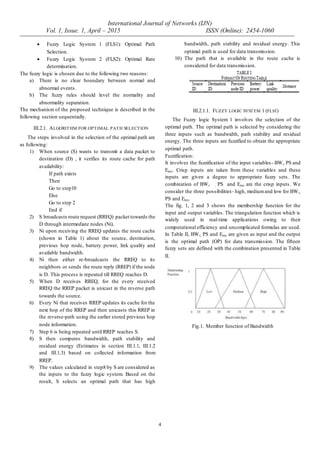
Fig.7. Rate vs. Delivery Ratio
Fig.8. Rate vs. Packet Drop
Fig.9. Rate vs. Residual Energy
Fig.7. shows the delivery ratio of this protocol and EEMAC
techniques fordifferent rate scenario.We can conclude that the
delivery ratio of our proposed approach has 27% of higher than
EEMAC approach.
Fig.8. shows the packet drop of the protocol and EEMAC
techniques fordifferent rate scenario.We can conclude that the
drop of our proposed approach has 11% of less than EEMAC
approach.
Fig.9. shows the residual energy of this protocol and
EEMAC techniques for different rate scenario. We can
conclude that the drop of our proposed approach has 2% higher
than EEMAC approach.
B. Based on Flow:
In our second experiment, we vary the number of flows as
2,4,6,8 and 10.](https://image.slidesharecdn.com/iisrtaarthiravindrannetworks-150705081002-lva1-app6892/85/Iisrt-aarthi-ravindran-networks-7-320.jpg)
![International Journal of Networks (IJN)
Vol. 1, Issue. 1, April – 2015 ISSN (Online): 2454-1060
8
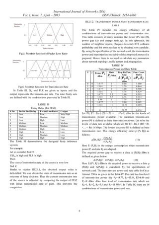
Fig.10. Flows vs. Delivery Ratio
Fig.11. Flows vs. Packet drop
Fig.12. Flows vs. Residual Energy
Fig.10. shows the delivery ratio of this protocol and
EEMAC technique for different rate scenario. We can conclude
that the delivery ratio of our proposed approach has 15% of
higher than EEMA C approach.
Fig.11. shows the packet drop of this protocol and EEMAC
techniques fordifferent rate scenario.We can conclude that the
drop of our proposed approach has 11% of less than EEMAC
approach.
Fig.12 shows the residual energy of this protocol and
EEMAC techniques for different rate scenario. We can
conclude that the residual energy of ourproposed approach has
14% higher than EEMAC approach.
V. CONCLUSION
In this paper, we have proposed a fuzzy based cross layer
routing in MANET in which the system comprises of two
fuzzy system namely fuzzy logic system 1 (FLS1) and fuzzy
logic system2 (FLS2).
By simulation results,this path selected by this approach is
more stable and more energy efficient. Also through this way
the network’s and node’s lifetime will be prolonged.
References
[1] Vahid Ayatollahi Tafti and Abolfazl Gandomi,
“Performance of QoS Parameters in MANET Application
Traffics in Large Scale Scenarios”, World Academy of
Science, Engineering and Technology, 2010.
[2] Al-Sakib Khan Pathan and Choong Seon Hong, “Routing
in Mobile Ad Hoc Network”, Guide to Wireless Ad Hoc
Network, 2009 edition.
[3] Serge Guillaume, “Designing Fuzzy Inference Systems
from Data: An Interpretability Oriented-Review, IEEE
Transaction on Fuzzy Systems, Vol. 9, NO. 3, June 2001.
[4] Vineet Srivastava ans Mehul Motani, “Cross-Layer Design:
A Survey and the Road Ahead”, IEEE Communication
Magazine, December 2005.
[5] A. Siddesh Gundagatti Karibasappa and B.K.N.
Muralidhara, “Neuro Fuzzy Based Routing Protocol for
Mobile Ad-Hoc Networks”, IEEE 6th
International
Conference on Industrial and Information Systems, (IICSI
2011), 2011.
[6] M. Niazi Torshiz, H. Amintoosi and A. Movaghar, “A
Fuzzy Energy-based Extension to AODV Routing”, IEEE
International Symposium on Telecommunications, 2008.
[7] Zuo Jing, Chi Xuefen, Lin Guan and Li Hongxia, “Service-
aware Multi-constrained Routing Protocol with QoS
Guarantee Based on Fuzzy Logic”, IEEE 22nd
International conference on Advanced Information
Networking and Applications- Workshops , 2008.
[8] Golnoosh Ghalavand, Arash Dana, Azadeh Ghalavand and
Mahnaz Rezahosieni, “Reliable routing algorithm based on
Fuzzy logic for Golnoosh Mobile Adhoc Network”, IEEE
3rd International Conference on Advanced Computer
Theory and Engineering (ICACTE), 2010.
[9] Cherine Fathy, M.T. El-Haddi and M.A.El-Nasr,
“Fuzzy-based Adaptive Cross Layer Routing Protocol for
Delay Sensitive Application in MANET”, IEEE
International Conference on Communications (ICC),
2012.
[10] Masaki Bandai, Satoshi Maeda, and Takashi Watanabe,
“Energy Efficient MAC Protocol with Power and Rate
Control in Multi-rate ad hoc networks”, IEEE, 2008.
[11] Mohammed Saghir, Tat-Chee Wan, Rahmat Budiarto,
“QoS Multicast Routing Based on Bandwidth Estimation in
Mobile Ad-Hoc Networks”, Proceedings of the Int. Conf.
On Computer and Communication Engineering
(ICCCE),Vol. I, 9-11, 2006.
[12] G N V Prasad, V. Siva Parvathi, Dr.K.Nageswara Rao,
“Link stability based multicast routing scheme inMANET”,
International Journal of Advanced Engineering Sciences
and Technologies (IJAEST), Vol No. 8, pp 169 – 176, Issue
No. 2, 2011.](https://image.slidesharecdn.com/iisrtaarthiravindrannetworks-150705081002-lva1-app6892/85/Iisrt-aarthi-ravindran-networks-8-320.jpg)
![International Journal of Networks (IJN)
Vol. 1, Issue. 1, April – 2015 ISSN (Online): 2454-1060
9
[13] Partha Sarathi Banerjee, J. Paulchoudhury and S. R.
Bhadra Chaudhuri, “Fuzzy Membership Function in a
Trust Based AODVfor MANET”, I. J. Computer Network
and Information Security, 2013.
[14] Dimitrios Liarokapis and Ali Shahrabi, “Fuzzy-based
Probabilistic Broadcasting in Mobile Ad Hoc Networks”,
IEEE International Conference on Wireless Days (WD),
IFIP, pp-1-6, 2011.
[15] Network Simulator: http //www.isi.edu/nsnam/ns](https://image.slidesharecdn.com/iisrtaarthiravindrannetworks-150705081002-lva1-app6892/85/Iisrt-aarthi-ravindran-networks-9-320.jpg)