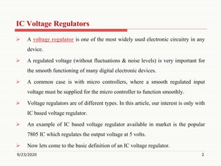
Presented by
Dr. R. RAJA, M.E., Ph.D.,
Assistant Professor, Department of EEE,
Muthayammal Engineering College, (Autonomous)
Namakkal (Dt), Rasipuram – 637408
Linear Integrated Circuits and Its Applications
IC Voltage Regulators
MUTHAYAMMAL ENGINEERING COLLEGE
(An Autonomous Institution)
(Approved by AICTE, New Delhi, Accredited by NAAC, NBA & Affiliated to Anna University),
Rasipuram - 637 408, Namakkal Dist., Tamil Nadu.
IC Voltage Regulators
 A voltage regulator is one of the most widely used electronic circuitry in any
device.
 A regulated voltage (without fluctuations & noise levels) is very important for
the smooth functioning of many digital electronic devices.
 A common case is with micro controllers, where a smooth regulated input
voltage must be supplied for the micro controller to function smoothly.
 Voltage regulators are of different types. In this article, our interest is only with
IC based voltage regulator.
 An example of IC based voltage regulator available in market is the popular
7805 IC which regulates the output voltage at 5 volts.
 Now lets come to the basic definition of an IC voltage regulator.
9/23/2020 2
 It is an integrated circuit whose basic purpose is to regulate the unregulated
input voltage (definitely over a predefined range) and provide with a constant,
regulated output voltage.
 An IC based voltage regulator can be classified in different ways. A common
type of classification is 3 terminal voltage regulator and 5 or multi terminal
voltage regulator.
 Another popular way of classifying IC voltage regulators is by identifying them
as linear voltage regulator & switching voltage regulator. There is a third set of
classification as
1) Fixed voltage regulators (positive & negative) 2) Adjustable voltage regulators
(positive & negative) and finally 3) Switching regulators. In the third classification,
fixed & adjustable regulators are basically versions of linear voltage regulators.
9/23/2020 3
Contd..
9/23/2020 4
Contd..
Fixed Voltage Regulators
 These regulators provide a constant output voltage. A popular example is the
7805 IC which provides a constant 5 volts output.
 A fixed voltage regulator can be a positive voltage regulator or a negative
voltage regulator.
 A positive voltage regulator provides with constant positive output voltage.
 All those IC’s in the 78XX series are fixed positive voltage regulators.
 In the IC nomenclature – 78XX ; the part XX denotes the regulated output
voltage the IC is designed for. Examples:- 7805, 7806, 7809 etc.
 A negative fixed voltage regulator is same as the positive fixed voltage
regulator in design, construction & operation.
9/23/2020 5
Contd..
 The only difference is in the polarity of output voltages. These IC’s are
designed to provide a negative output voltage. Example:- 7905, 7906 and all
those IC’s in the 79XX series.
Adjustable Voltage Regulator
 An adjustable voltage regulator is a kind of regulator whose regulated output
voltage can be varied over a range.
 There are two variations of the same; known as positive adjustable voltage
regulator and negative adjustable regulator.
 LM317 is a classic example of positive adjustable voltage regulator, whose
output voltage can be varied over a range of 1.2 volts to 57 volts.
 LM337 is an example of negative adjustable voltage regulator.
9/23/2020 6
Contd..
 LM337 is actually a complement of LM317 which are similar in operation &
design; with the only difference being polarity of regulated output voltage.
 There may be certain conditions where a variable voltage may be required.
 Right now we shall discuss how an LM317 adjustable positive voltage regulator
IC is connected. The connection diagram is shown below.
9/23/2020 7
Contd..
 The resistors R1 and R2 determine the output voltage Vout.
 The resistor R2 is adjusted to get the output voltage range between 1.2 volts to
57 volts. The output voltage that is required can be calculated using the
equation: Vout = Vref (1+R2/R1) + Iadj R2
 In this circuit, the value of Vref is the reference voltage between the adjustment
terminals and the output taken as 1.25 Volt.
 The value of Iadj will be very small and will also have a constant value. Thus
the above equation can be rewritten as Vout = 1.25 (1+R2/R1)
9/23/2020 8
Contd..
 In the above equation, due to the small value of Iadj, the drop due to R2 is
neglected.
 The load regulation is 0.1 percent while the line regulation is 0.01 percent per
volt.
 This means that the output voltage varies only 0.01 percent for each volt of
input voltage. The ripple rejection is 80 db, equivalent to 10,000.
 The LM 337 series of adjustable voltage regulators is a complement to the LM
317 series devices.
 The negative adjustable voltage regulators are available in the same voltage and
current options as the LM 317 devices.
9/23/2020 9
Contd..
Switching Voltage Regulators
 Switching regulators differ in design, construction & operation compared to
linear voltage regulators.
 In switching regulators the output voltage is regulated by controlling the
switching time of feedback circuitry (which includes a reference voltage); that
is by adjusting the duty cycle.
 The regulators discussed above are all linear voltage regulators which need a
series pass transistor to regulate in the active region.
 Though they are chosen for different purposes, they do have a disadvantage of
high power dissipation of the series pass transistor.
9/23/2020 10
Contd..
 The main reason is because the series pass transistor is used as a Class A power
amplifier which is known for its low efficiency and power loss in the form of
heat.
 The series pass resistor will have to carry a heavy load when the load current
increases.
 This causes the series pass transistor to get bulky with a bulkier heat sink.
 This in turn increases the overall cost as well. Such linear regulators will also
need a step-down transformer which again increases the size of the overall
circuit.
 The large ripples produced by the circuit should be eliminated and this requires
large sized filter capacitors.
9/23/2020 11
Contd..
 All these problems can be solved by using a switching voltage regulator.
 The whole operation is completely different when compared to a linear voltage
regulator. Here, the series pass transistor is not used as an amplifier, but as a
switch.
 That is, instead of the transistor working in the active region, it is made to
switch between the saturation region or cut-off region.
 Thus, the power dissipation is lessened and thus can carry heavy load currents
at low voltages with less bulky heat sinks. Thus, this regulator finds its
extensive use in personal computers.
 The basic switching regulator is designed to work in three configurations. Their
circuit diagrams and explanation are given below..
9/23/2020 12
Contd..
9/23/2020 13
Contd..
Switching Voltage Regulator – Types
Step-down Switching Regulator
 As shown in the figure above, the rectangular pulses are given to the base of the
transistor. During each cycle of the pulse the transistor changes between
saturation and cut-off.
 This creates a rectangular voltage at the input to LC filter.
 The ac components of the input voltage to the filter is blocked and the dc
component is allowed to pass through the filter.
 As the transistor keeps switching, the average value will always be lesser than
the input voltage.
 This is why we call it the “step-down” switching regulator.
9/23/2020 14
Step-up Switching Regulator
 As shown in the figure above, the rectangular pulses are given to the base of the
transistor.
 During each cycle of the pulse the transistor changes between saturation and
cut-off.
 When the transistor is saturated the current flows through the inductor. When
the transistor switches to cut-off a large voltage will be induced across the
inductor coil because of the sudden collapse of the magnetic field around it.
 Thus the current keeps flowing in the same direction. The circuit is called a
“step-up” switching regulator because the voltage induced by the inductor will
be larger than the input voltage.
9/23/2020 15
Contd..
Polarity Inverting Switching Regulatory
 As shown in the figure above, when the transistor is saturated, the current flows
through the inductor.
 When the transistor switches to cut-off a large voltage will be induced across
the inductor coil because of the sudden collapse of the magnetic field around it.
 Thus the current keeps flowing in the same direction.Since the transistor is cut-
off, the only path is through the capacitor.
 If the direction of charging current through the capacitor is checked, output
voltage is found to be negative.
9/23/2020 16
Contd..
9/23/2020 17
Contd..
 A simple switching regulator is designed with the mix of circuits that we
already know.
 The working starts with the relaxation oscillator which generates a square wave.
 The frequency of the square wave is decided by the values of R5 and C3. The
square wave is given as input to the integrator and produces an output triangular
wave.
 This is given as input to the positive terminal of the triangle to pulse converter.
 The output pulse will then drive the base of the pass transistor. The duty cycle
of these pulses will determine the output voltage.
 The duty cycle D is the ratio of the ON time W to the time period T
9/23/2020 18
Contd..
 By controlling the duty cycle of the pulse generator, the duty cycle of the input
voltage to the LC filter is controlled.
 The output of the LC filter is a dc voltage with only a small ripple. This output
Vout = Dvin
Since D can vary from 0 to 1, Vout can vary from 0 to Vin.
 A simple voltage divider is used to sample the output of the LC filter.
 This voltage is then fedback to the comparator circuit where a reference voltage
Vref is compared with the output voltage and passed on to the negative input of
the triangle to pulse converter.
9/23/2020 19
Contd..
 When the output voltage increases, the comparator circuit produces a higher
output voltage and thus the inverting input of the triangle to pulse converter will
have high value.
 This will narrow down the pulses at the base input of the pass transistor. Since
the duty cycle is lower, the filtered output voltage is less, which tends to cancel
almost all the original increase in the output voltage.
 It means that any attempted increase in output voltage generates a negative
feedback voltage that almost eliminates the original increase.
 Reverse happens should the output voltage fall.
9/23/2020 20
Contd..
 There is enough open-loop gain in the system to ensure a well-regulated output
voltage. Since the error voltage to the comparator is near zero, the voltage
across R2 is approximately equal to Vref. So the current through resistor R2 is:
I = Vref / R2
 This current flows through R1 , which means the output voltage is
Vout = Vref (R1 + R2)
 Switching regulators are available in different configurations like the flyback
configuration, feed-forward, push-pull, and non-isolated single-ended or single-
polarity types.
 Some of the common IC’s used as switching regulators in the above said
configurations are the LM 1577/LM 2577 IC’s.
9/23/2020 21
Contd..
Thank You
9/23/2020 22

Voltage Regulators IC

  • 1.
    Presented by Dr. R.RAJA, M.E., Ph.D., Assistant Professor, Department of EEE, Muthayammal Engineering College, (Autonomous) Namakkal (Dt), Rasipuram – 637408 Linear Integrated Circuits and Its Applications IC Voltage Regulators MUTHAYAMMAL ENGINEERING COLLEGE (An Autonomous Institution) (Approved by AICTE, New Delhi, Accredited by NAAC, NBA & Affiliated to Anna University), Rasipuram - 637 408, Namakkal Dist., Tamil Nadu.
  • 2.
    IC Voltage Regulators A voltage regulator is one of the most widely used electronic circuitry in any device.  A regulated voltage (without fluctuations & noise levels) is very important for the smooth functioning of many digital electronic devices.  A common case is with micro controllers, where a smooth regulated input voltage must be supplied for the micro controller to function smoothly.  Voltage regulators are of different types. In this article, our interest is only with IC based voltage regulator.  An example of IC based voltage regulator available in market is the popular 7805 IC which regulates the output voltage at 5 volts.  Now lets come to the basic definition of an IC voltage regulator. 9/23/2020 2
  • 3.
     It isan integrated circuit whose basic purpose is to regulate the unregulated input voltage (definitely over a predefined range) and provide with a constant, regulated output voltage.  An IC based voltage regulator can be classified in different ways. A common type of classification is 3 terminal voltage regulator and 5 or multi terminal voltage regulator.  Another popular way of classifying IC voltage regulators is by identifying them as linear voltage regulator & switching voltage regulator. There is a third set of classification as 1) Fixed voltage regulators (positive & negative) 2) Adjustable voltage regulators (positive & negative) and finally 3) Switching regulators. In the third classification, fixed & adjustable regulators are basically versions of linear voltage regulators. 9/23/2020 3 Contd..
  • 4.
  • 5.
    Fixed Voltage Regulators These regulators provide a constant output voltage. A popular example is the 7805 IC which provides a constant 5 volts output.  A fixed voltage regulator can be a positive voltage regulator or a negative voltage regulator.  A positive voltage regulator provides with constant positive output voltage.  All those IC’s in the 78XX series are fixed positive voltage regulators.  In the IC nomenclature – 78XX ; the part XX denotes the regulated output voltage the IC is designed for. Examples:- 7805, 7806, 7809 etc.  A negative fixed voltage regulator is same as the positive fixed voltage regulator in design, construction & operation. 9/23/2020 5 Contd..
  • 6.
     The onlydifference is in the polarity of output voltages. These IC’s are designed to provide a negative output voltage. Example:- 7905, 7906 and all those IC’s in the 79XX series. Adjustable Voltage Regulator  An adjustable voltage regulator is a kind of regulator whose regulated output voltage can be varied over a range.  There are two variations of the same; known as positive adjustable voltage regulator and negative adjustable regulator.  LM317 is a classic example of positive adjustable voltage regulator, whose output voltage can be varied over a range of 1.2 volts to 57 volts.  LM337 is an example of negative adjustable voltage regulator. 9/23/2020 6 Contd..
  • 7.
     LM337 isactually a complement of LM317 which are similar in operation & design; with the only difference being polarity of regulated output voltage.  There may be certain conditions where a variable voltage may be required.  Right now we shall discuss how an LM317 adjustable positive voltage regulator IC is connected. The connection diagram is shown below. 9/23/2020 7 Contd..
  • 8.
     The resistorsR1 and R2 determine the output voltage Vout.  The resistor R2 is adjusted to get the output voltage range between 1.2 volts to 57 volts. The output voltage that is required can be calculated using the equation: Vout = Vref (1+R2/R1) + Iadj R2  In this circuit, the value of Vref is the reference voltage between the adjustment terminals and the output taken as 1.25 Volt.  The value of Iadj will be very small and will also have a constant value. Thus the above equation can be rewritten as Vout = 1.25 (1+R2/R1) 9/23/2020 8 Contd..
  • 9.
     In theabove equation, due to the small value of Iadj, the drop due to R2 is neglected.  The load regulation is 0.1 percent while the line regulation is 0.01 percent per volt.  This means that the output voltage varies only 0.01 percent for each volt of input voltage. The ripple rejection is 80 db, equivalent to 10,000.  The LM 337 series of adjustable voltage regulators is a complement to the LM 317 series devices.  The negative adjustable voltage regulators are available in the same voltage and current options as the LM 317 devices. 9/23/2020 9 Contd..
  • 10.
    Switching Voltage Regulators Switching regulators differ in design, construction & operation compared to linear voltage regulators.  In switching regulators the output voltage is regulated by controlling the switching time of feedback circuitry (which includes a reference voltage); that is by adjusting the duty cycle.  The regulators discussed above are all linear voltage regulators which need a series pass transistor to regulate in the active region.  Though they are chosen for different purposes, they do have a disadvantage of high power dissipation of the series pass transistor. 9/23/2020 10 Contd..
  • 11.
     The mainreason is because the series pass transistor is used as a Class A power amplifier which is known for its low efficiency and power loss in the form of heat.  The series pass resistor will have to carry a heavy load when the load current increases.  This causes the series pass transistor to get bulky with a bulkier heat sink.  This in turn increases the overall cost as well. Such linear regulators will also need a step-down transformer which again increases the size of the overall circuit.  The large ripples produced by the circuit should be eliminated and this requires large sized filter capacitors. 9/23/2020 11 Contd..
  • 12.
     All theseproblems can be solved by using a switching voltage regulator.  The whole operation is completely different when compared to a linear voltage regulator. Here, the series pass transistor is not used as an amplifier, but as a switch.  That is, instead of the transistor working in the active region, it is made to switch between the saturation region or cut-off region.  Thus, the power dissipation is lessened and thus can carry heavy load currents at low voltages with less bulky heat sinks. Thus, this regulator finds its extensive use in personal computers.  The basic switching regulator is designed to work in three configurations. Their circuit diagrams and explanation are given below.. 9/23/2020 12 Contd..
  • 13.
  • 14.
    Switching Voltage Regulator– Types Step-down Switching Regulator  As shown in the figure above, the rectangular pulses are given to the base of the transistor. During each cycle of the pulse the transistor changes between saturation and cut-off.  This creates a rectangular voltage at the input to LC filter.  The ac components of the input voltage to the filter is blocked and the dc component is allowed to pass through the filter.  As the transistor keeps switching, the average value will always be lesser than the input voltage.  This is why we call it the “step-down” switching regulator. 9/23/2020 14
  • 15.
    Step-up Switching Regulator As shown in the figure above, the rectangular pulses are given to the base of the transistor.  During each cycle of the pulse the transistor changes between saturation and cut-off.  When the transistor is saturated the current flows through the inductor. When the transistor switches to cut-off a large voltage will be induced across the inductor coil because of the sudden collapse of the magnetic field around it.  Thus the current keeps flowing in the same direction. The circuit is called a “step-up” switching regulator because the voltage induced by the inductor will be larger than the input voltage. 9/23/2020 15 Contd..
  • 16.
    Polarity Inverting SwitchingRegulatory  As shown in the figure above, when the transistor is saturated, the current flows through the inductor.  When the transistor switches to cut-off a large voltage will be induced across the inductor coil because of the sudden collapse of the magnetic field around it.  Thus the current keeps flowing in the same direction.Since the transistor is cut- off, the only path is through the capacitor.  If the direction of charging current through the capacitor is checked, output voltage is found to be negative. 9/23/2020 16 Contd..
  • 17.
  • 18.
     A simpleswitching regulator is designed with the mix of circuits that we already know.  The working starts with the relaxation oscillator which generates a square wave.  The frequency of the square wave is decided by the values of R5 and C3. The square wave is given as input to the integrator and produces an output triangular wave.  This is given as input to the positive terminal of the triangle to pulse converter.  The output pulse will then drive the base of the pass transistor. The duty cycle of these pulses will determine the output voltage.  The duty cycle D is the ratio of the ON time W to the time period T 9/23/2020 18 Contd..
  • 19.
     By controllingthe duty cycle of the pulse generator, the duty cycle of the input voltage to the LC filter is controlled.  The output of the LC filter is a dc voltage with only a small ripple. This output Vout = Dvin Since D can vary from 0 to 1, Vout can vary from 0 to Vin.  A simple voltage divider is used to sample the output of the LC filter.  This voltage is then fedback to the comparator circuit where a reference voltage Vref is compared with the output voltage and passed on to the negative input of the triangle to pulse converter. 9/23/2020 19 Contd..
  • 20.
     When theoutput voltage increases, the comparator circuit produces a higher output voltage and thus the inverting input of the triangle to pulse converter will have high value.  This will narrow down the pulses at the base input of the pass transistor. Since the duty cycle is lower, the filtered output voltage is less, which tends to cancel almost all the original increase in the output voltage.  It means that any attempted increase in output voltage generates a negative feedback voltage that almost eliminates the original increase.  Reverse happens should the output voltage fall. 9/23/2020 20 Contd..
  • 21.
     There isenough open-loop gain in the system to ensure a well-regulated output voltage. Since the error voltage to the comparator is near zero, the voltage across R2 is approximately equal to Vref. So the current through resistor R2 is: I = Vref / R2  This current flows through R1 , which means the output voltage is Vout = Vref (R1 + R2)  Switching regulators are available in different configurations like the flyback configuration, feed-forward, push-pull, and non-isolated single-ended or single- polarity types.  Some of the common IC’s used as switching regulators in the above said configurations are the LM 1577/LM 2577 IC’s. 9/23/2020 21 Contd..
  • 22.