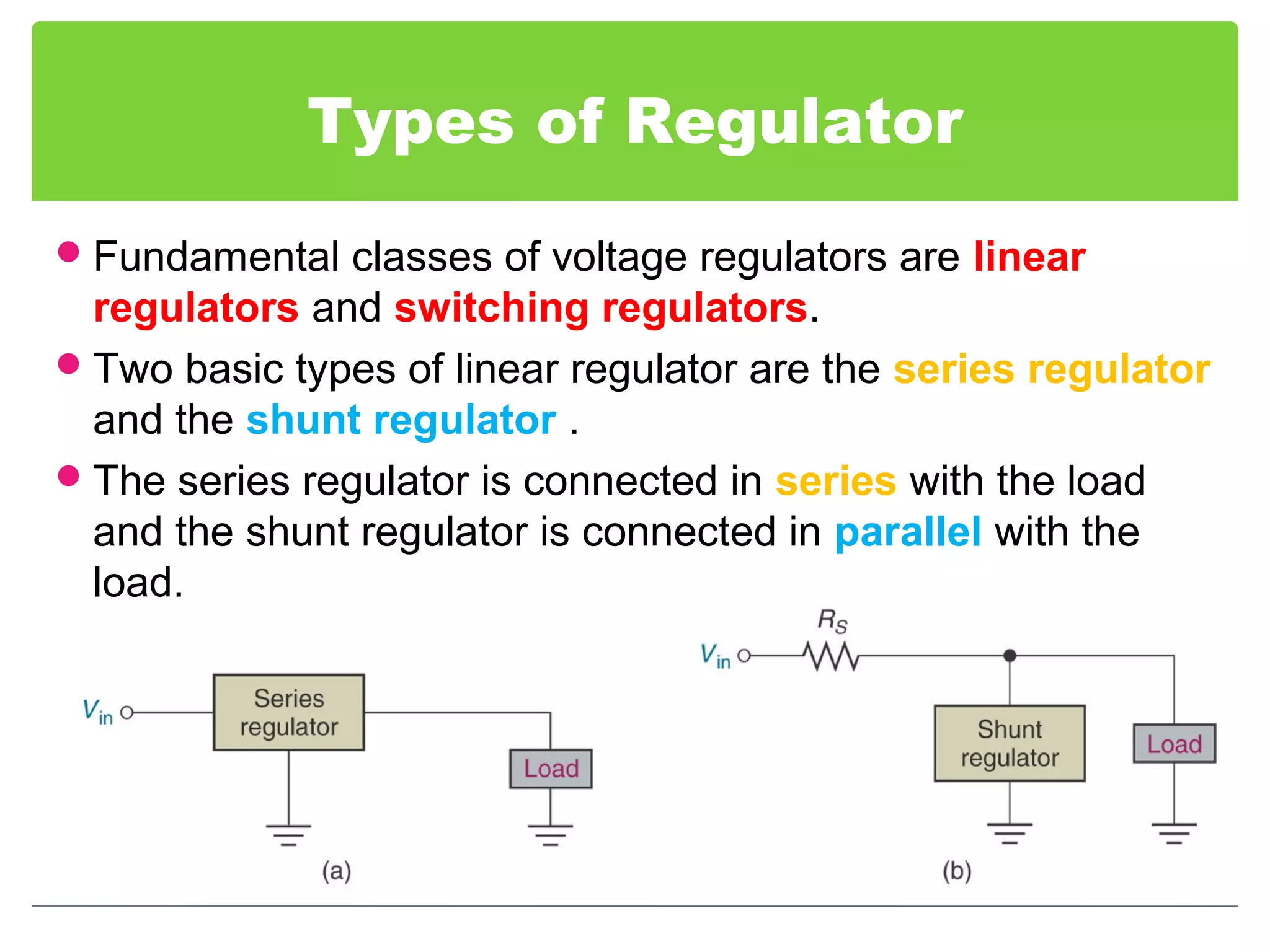
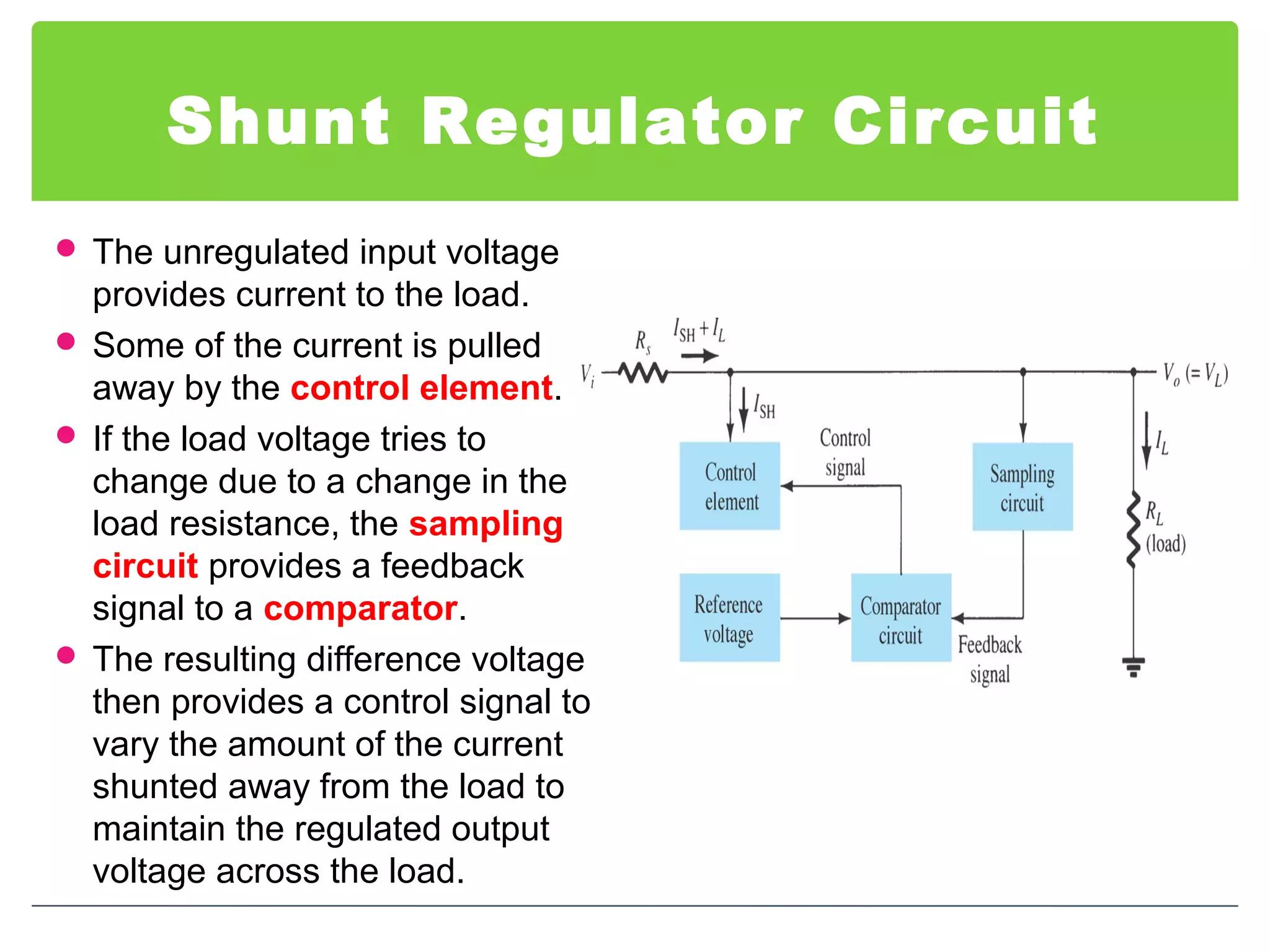
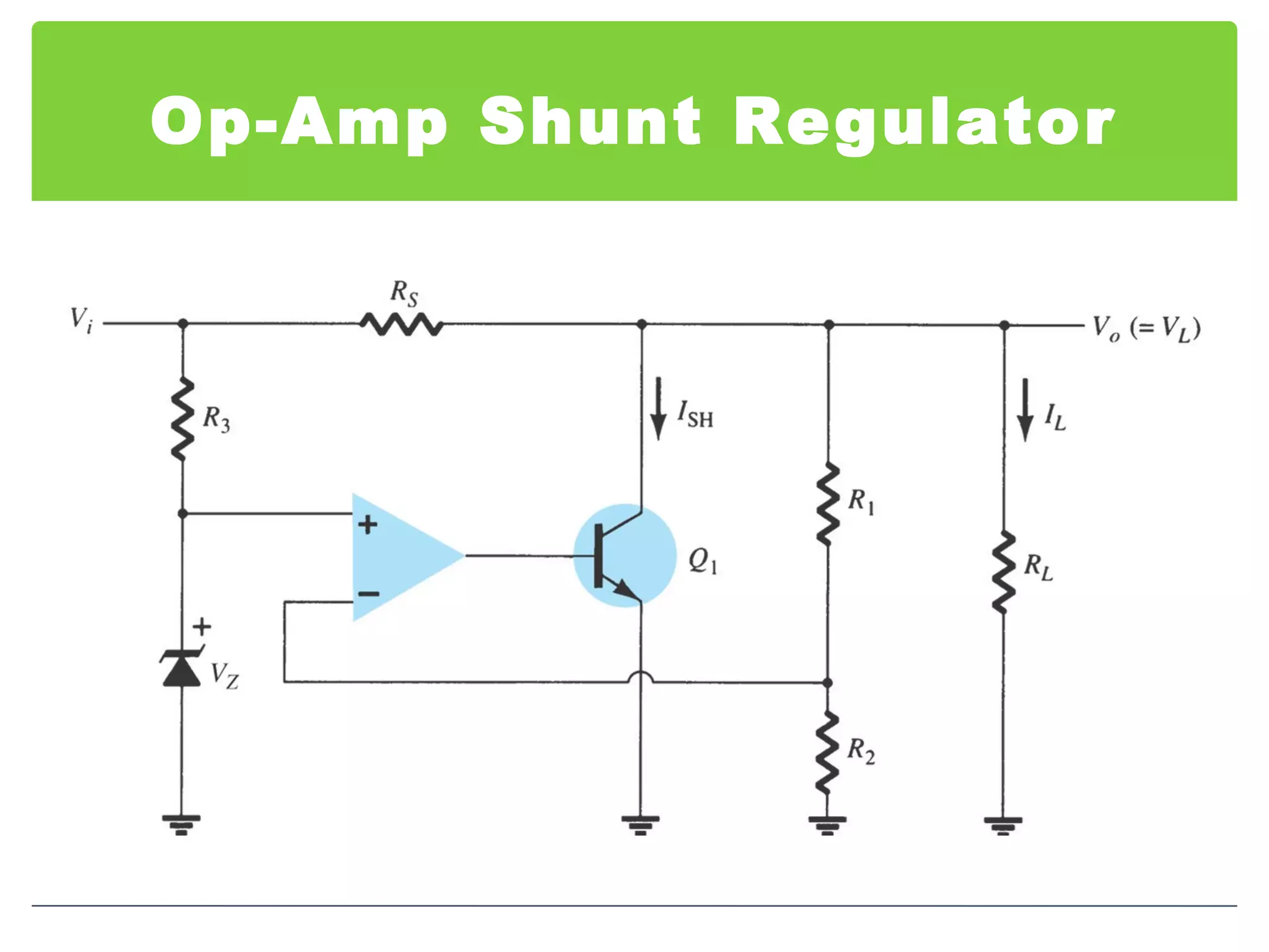
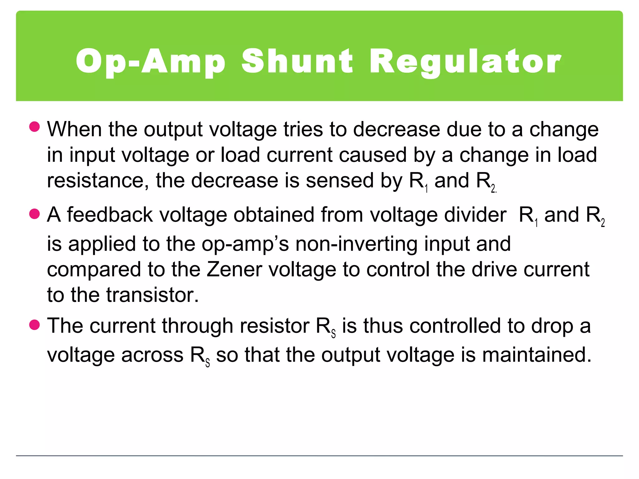
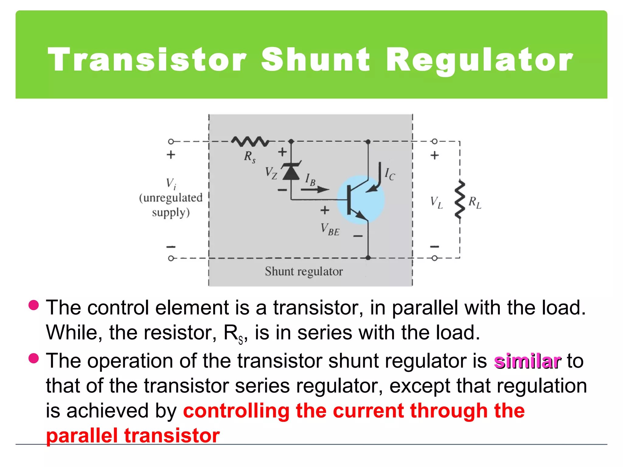
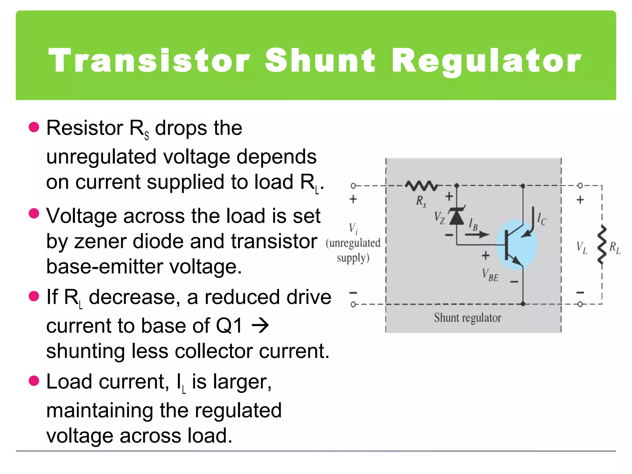
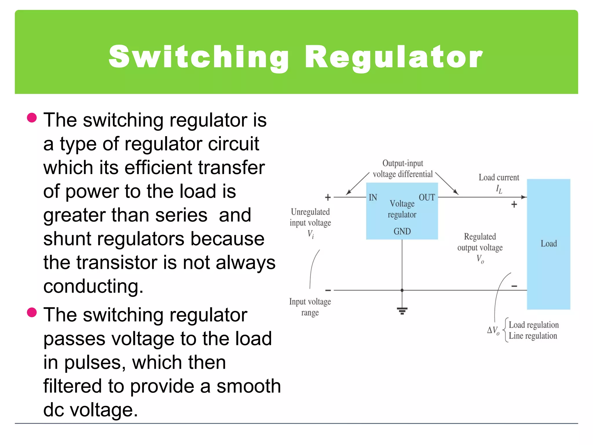
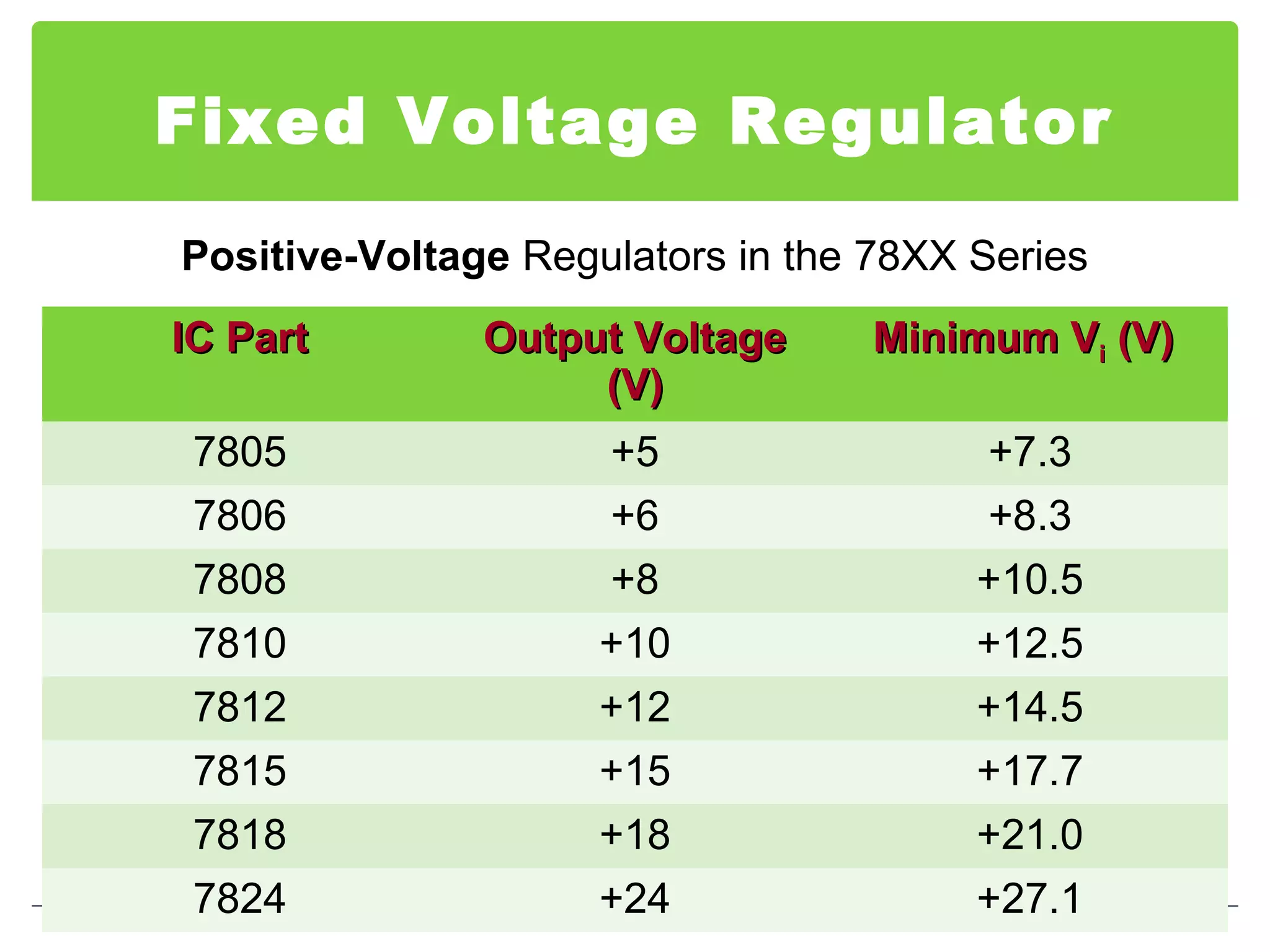
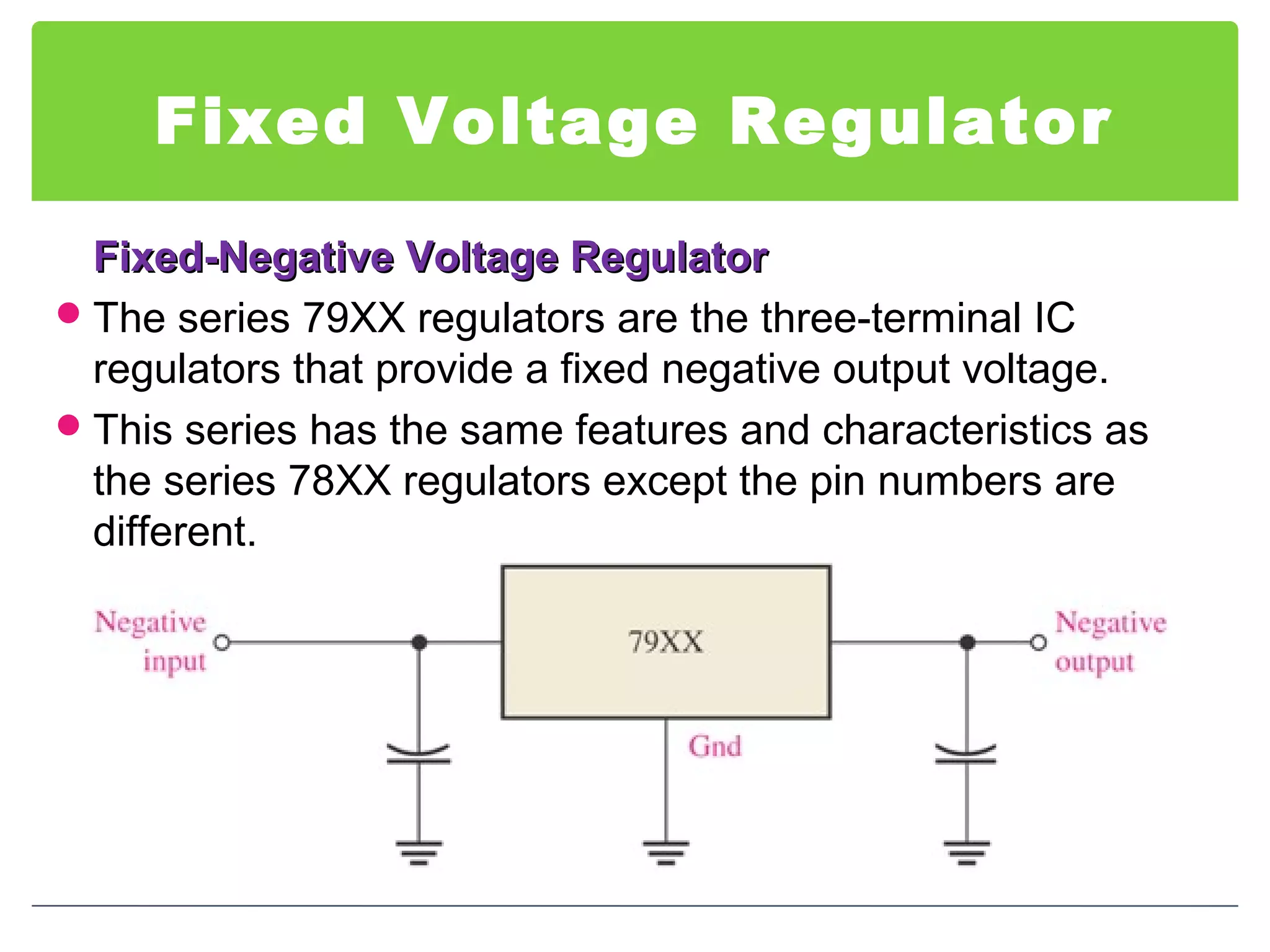
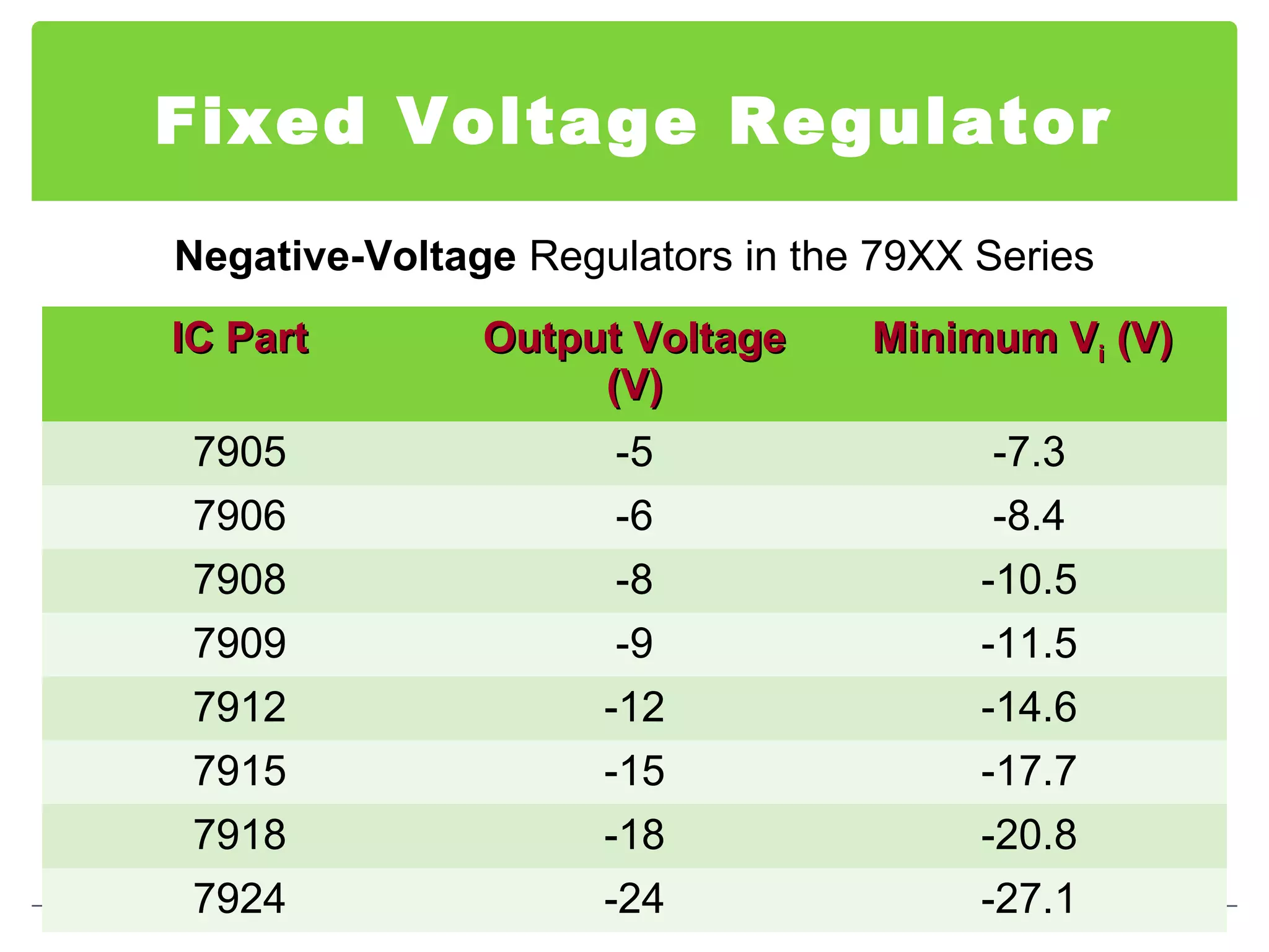
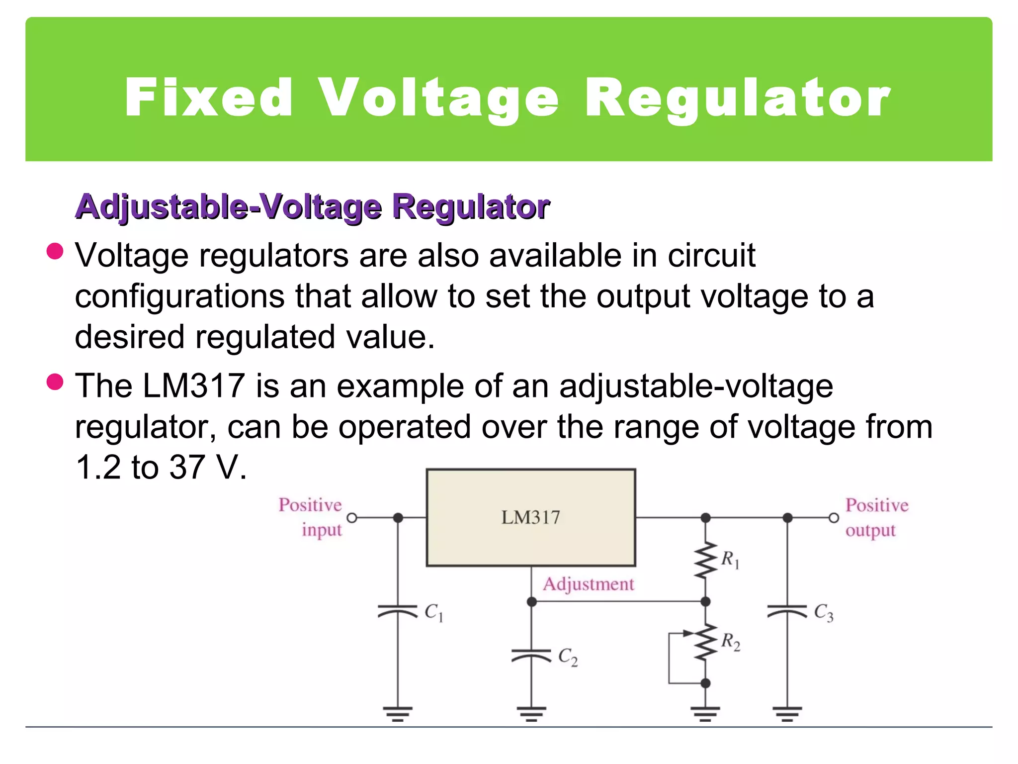
3. Introduction
īBatteries are often shown on a schematic diagram as the
source of DC voltage but usually the actual DC voltage
source is a power supply.
īThere are many types of power supply. Most are designed
to convert high voltage AC mains electricity to a suitable
low voltage supply for electronics circuits and other devices.
īA more reliable method of obtaining DC power is to
transform, rectify, filter and regulate an AC line voltage.
īA power supply can by broken down into a series of blocks,
each of which performs a particular function.
4. Introduction
īPower supplyPower supply: a group of circuits that convert the
standard ac voltage (120 V, 60 Hz) provided by the wall
outlet to constant dc voltage
īTransformerTransformer : a device that step up or step down the ac
voltage provided by the wall outlet to a desired amplitude
through the action of a magnetic field
5. Introduction
ī RectifierRectifier: a diode circuits that converts the ac input
voltage to a pulsating dc voltage
ī The pulsating dc voltage is only suitable to be used as a
battery charger, but not good enough to be used as a dc
power supply in a radio, stereo system, computer and so
on.
6. Introduction
ī There are two basic types of rectifier circuits:
ī Half-wave rectifier
ī Full-wave rectifier - Center-tapped & Bridge full-wave rectifier
ī In summary, a full-wave rectified signal has less ripple
than a half-wave rectified signal and is thus better to apply
to a filter.
7. Introduction
ī FilterFilter: a circuit used to reduce the fluctuation in the
rectified output voltage or ripple. This provides a steadier
dc voltage.
ī RegulatorRegulator: a circuit used to produces a constant dc
output voltage by reducing the ripple to negligible amount.
One part of power supply.
8. Introduction
RegulatorRegulator - Zener diode regulator
īFor low current power supplies - a simple voltage regulator
can be made with a resistor and a zener diode connected in
reverse.
īZener diodes are rated by their breakdown voltage Vz and
maximum power Pz (typically 400mW or 1.3W)
9. Voltage Regulation
īTwo basic categories of voltage regulation are:
īą line regulation
īą load regulation
īThe purpose of line regulationline regulation is to maintain a nearly
constant output voltage when the input voltageinput voltage varies.
īThe purpose of load regulationload regulation is to maintain a nearly
constant output voltage when the loadload varies
10. Line Regulation
Line regulation: A change in input (line) voltage does not significantly affect the
output voltage of a regulator (within certain limits)
11. Line Regulation
īLine regulation can be defined as the percentage change in
the output voltage for a given change in the input voltage.
Î means âa change inâ
īLine regulation can be calculated using the following
formula:
%100ÃīŖˇīŖˇ
īŖ¸
īŖļ
īŖŦīŖŦ
īŖ
īŖĢ
â
â
=
IN
OUT
V
V
regulationLine
( )
IN
OUTOUT
V
VV
regulationLine
â
Ãâ
=
%100/
12. Load Regulation
Load regulation: A change in load current (due to a varying RL) has practically no
effect on the output voltage of a regulator (within certain limits)
13. Load Regulation
īLoad regulation can be defined as the percentage change
in the output voltage from no-load (NL) to full-load (FL).
īWhere:
VNL = the no-load output voltage
VFL = the full-load output voltage
%100ÃīŖˇīŖˇ
īŖ¸
īŖļ
īŖŦīŖŦ
īŖ
īŖĢ â
=
FL
FLNL
V
VV
regulationLoad
14. Load Regulation
īSometimes power supply manufacturers specify the
equivalent output resistance (Rout) instead of its load
regulation.
īRFL equal the smallest-rated load resistance, then VFL:
īŖˇīŖˇ
īŖ¸
īŖļ
īŖŦīŖŦ
īŖ
īŖĢ
â
=
FLOUT
FL
NLFL
RR
R
VV
15. Load Regulation
īRearrange the equation:
%100
%1001
%100
ÃīŖˇīŖˇ
īŖ¸
īŖļ
īŖŦīŖŦ
īŖ
īŖĢ
=
ÃīŖˇīŖˇ
īŖ¸
īŖļ
īŖŦīŖŦ
īŖ
īŖĢ
â
â
=
Ã
âīŖˇīŖˇ
īŖ¸
īŖļ
īŖŦīŖŦ
īŖ
īŖĢ â
=
īŖˇīŖˇ
īŖ¸
īŖļ
īŖŦīŖŦ
īŖ
īŖĢ â
=
FL
OUT
FL
FLOUT
FL
FL
FL
FLOUT
FL
FL
FLOUT
FLNL
R
R
regulationLoad
R
RR
regulationLoad
V
V
R
RR
V
regulationLoad
R
RR
VV
16. Example
1. The input of a certain regulator increases by 3.5 V. As a
result, the output voltage increases by 0.042 V. The
nominal output is 20 V. Determine the line regulation in
both % and in %/V.
(Solution: 1.2% ; 0.06%/V)
2. If a 5 V power supply has an output resistance of 80 mâĻ
and a specific maximum output current of 1 A. Calculate
the load regulation in % and %/mA.
(Solution: 1.6% ; 0.0016%/mA)
17. Types of Regulator
īFundamental classes of voltage regulators are linear
regulators and switching regulators.
īTwo basic types of linear regulator are the series regulator
and the shunt regulator .
īThe series regulator is connected in series with the load
and the shunt regulator is connected in parallel with the
load.
18. Series Regulator Circuit
īControl element in series
with load between input
and output.
īOutput sample circuit
senses a change in output
voltage.
īError detector compares
sample voltage with
reference voltage â
causes control element to
compensate in order to
maintain a constant output
voltage.
20. Op-Amp Series Regulator
īThe resistor R1 and R2 sense a change in the output voltage
and provide a feedback voltage.
īThe error detector compares the feedback voltage with a
Zener diode reference voltage.
īThe resulting difference voltage causes the transistor Q1
controls the conduction to compensate the variation of the
output voltage.
īThe output voltage will be maintained at a constant value
of:
Zo V
R
R
V īŖˇīŖˇ
īŖ¸
īŖļ
īŖŦīŖŦ
īŖ
īŖĢ
+=
2
1
1
22. Transistor Series Regulator
īSince Q1 is an npn transistor, Vo is found as:
īthe response of the pass-transistor to a change in load
resistance as follows:
īIf load resistance increases, load voltage also increases.
īSince the Zener voltage is constant, the increase in Vo causes VBE to
decrease.
īThe decrease in VBE reduces conduction through the pass- transistor,
so load current decreases.
īThis offsets the increase in load resistance, and a relatively constant
load voltage is maintained
oZBE VVV â=
25. Shunt Regulator Circuit
ī The unregulated input voltage
provides current to the load.
ī Some of the current is pulled
away by the control element.
ī If the load voltage tries to
change due to a change in the
load resistance, the sampling
circuit provides a feedback
signal to a comparator.
ī The resulting difference voltage
then provides a control signal to
vary the amount of the current
shunted away from the load to
maintain the regulated output
voltage across the load.
27. Op-Amp Shunt Regulator
īWhen the output voltage tries to decrease due to a change
in input voltage or load current caused by a change in load
resistance, the decrease is sensed by R1 and R2.
īA feedback voltage obtained from voltage divider R1 and R2
is applied to the op-ampâs non-inverting input and
compared to the Zener voltage to control the drive current
to the transistor.
īThe current through resistor RS is thus controlled to drop a
voltage across RS so that the output voltage is maintained.
28. Transistor Shunt Regulator
īThe control element is a transistor, in parallel with the load.
While, the resistor, RS, is in series with the load.
īThe operation of the transistor shunt regulator is similarsimilar to
that of the transistor series regulator, except that regulation
is achieved by controlling the current through the
parallel transistor
29. Transistor Shunt Regulator
īResistor RS drops the
unregulated voltage depends
on current supplied to load RL.
īVoltage across the load is set
by zener diode and transistor
base-emitter voltage.
īIf RL decrease, a reduced drive
current to base of Q1 ī
shunting less collector current.
īLoad current, IL is larger,
maintaining the regulated
voltage across load.
30. Transistor Shunt Regulator
īThe output voltage to the load is:
īvoltage across the load is set by the Zener diode voltage
and the transistor base-emitter voltage.
īIf the load resistance decreases, the load current will be
larger at a value of:
īThe increase in load current causes the collector current
shunted by the transistor is to be less:
īThe current through RS:
BEZLo VVVV +==
L
L
L
R
V
I =
LSC III â=
S
Li
S
R
VV
I
â
=
32. Switching Regulator
īThe switching regulator is
a type of regulator circuit
which its efficient transfer
of power to the load is
greater than series and
shunt regulators because
the transistor is not always
conducting.
īThe switching regulator
passes voltage to the load
in pulses, which then
filtered to provide a smooth
dc voltage.
33. Switching Regulator
īThe switching regulator is more efficient than the linear
series or shunt type.
īThis type regulator is ideal for high current applications
since less power is dissipated.
īVoltage regulation in a switching regulator is achieved by
the on and off action limiting the amount of current flow
based on the varying line and load conditions.
īWith switching regulators 90% efficiencies can be achieved.
34. Switching Regulator
Step-Down Configuration
īWith the step-down (output is less than the input)
configuration the control element Q1 is pulsed on and off at
variable rate based on the load current.
īThe pulsations are filtered out by the LC filter.
35. Switching Regulator
Step-up configuration
īThe difference is in the placement of the inductor and the
fact that Q1 is shunt configured.
īDuring the time when Q1 is off the VL adds to VC stepping the
voltage up by some amount.
36. Switching Regulator
Voltage-inverter configuration
īoutput voltage is of opposite polarity of the input.
īThis is achieved by VL forward-biasing reverse-biased diode
during the off times producing current and charging the
capacitor for voltage production during the off times.
īWith switching regulators 90% efficiencies can be achieved.
37. IC Voltage Regulators
īRegulation circuits in integrated circuit form are widely
used.
īTheir operation is no different but they are treated as a
single device with associated components.
īThese are generally three terminal devices that provide a
positive or negative output.
īSome types have variable voltage outputs.
īA typical 7800 series voltage regulator is used for positive
voltages.
īThe 7900 series are negative voltage regulators.
īThese voltage regulators when used with heatsinks can
safely produce current values of 1A and greater.
īThe capacitors act as line filtration.
38. IC Voltage Regulators
īSeveral types of both linear (series and shunt) and
switching regulators are available in integrated circuit (IC)
form.
īSingle IC regulators contain the circuitry for:
(1) reference source
(2) comparator amplifier
(3) control device
(4) overload protection
īGenerally, the linear regulators are three-terminal devices
that provides either positive or negative output voltages that
can be either fixed or adjustable.
39. Fixed Voltage Regulator
īThe fixed voltage regulator has an unregulated dc input
voltage Vi applied to one input terminal, a regulated output
dc voltage Vo from a second terminal, and the third terminal
connected to ground.
Fixed-Positive Voltage RegulatorFixed-Positive Voltage Regulator
īThe series 78XX regulators are the three-terminal devices
that provide a fixed positive output voltage.
40. Fixed Voltage Regulator
īAn unregulated input
voltage Vi is filtered by a
capacitor C1 and connected
to the ICâs IN terminal.
īThe ICâs OUT terminal
provides a regulated +12
V, which is filtered by
capacitor C2.
īThe third IC terminal is
connected to ground
(GND)
41. Fixed Voltage Regulator
IC PartIC Part Output VoltageOutput Voltage
(V)(V)
Minimum VMinimum Vii (V)(V)
7805 +5 +7.3
7806 +6 +8.3
7808 +8 +10.5
7810 +10 +12.5
7812 +12 +14.5
7815 +15 +17.7
7818 +18 +21.0
7824 +24 +27.1
Positive-Voltage Regulators in the 78XX Series
42. Fixed Voltage Regulator
Fixed-Negative Voltage RegulatorFixed-Negative Voltage Regulator
īThe series 79XX regulators are the three-terminal IC
regulators that provide a fixed negative output voltage.
īThis series has the same features and characteristics as
the series 78XX regulators except the pin numbers are
different.
43. Fixed Voltage Regulator
IC PartIC Part Output VoltageOutput Voltage
(V)(V)
Minimum VMinimum Vii (V)(V)
7905 -5 -7.3
7906 -6 -8.4
7908 -8 -10.5
7909 -9 -11.5
7912 -12 -14.6
7915 -15 -17.7
7918 -18 -20.8
7924 -24 -27.1
Negative-Voltage Regulators in the 79XX Series
44. Fixed Voltage Regulator
Adjustable-Voltage RegulatorAdjustable-Voltage Regulator
īVoltage regulators are also available in circuit
configurations that allow to set the output voltage to a
desired regulated value.
īThe LM317 is an example of an adjustable-voltage
regulator, can be operated over the range of voltage from
1.2 to 37 V.
45. Summary
īVoltage regulators keep a constant dc output
despite input voltage or load changes.
īThe two basic categories of voltage regulators are
linear and switching.
īThe two types of linear voltage regulators are
series and shunt.
īThe three types of switching are step-up, step-
down, and inverting.
46. Summary
īSwitching regulators are more efficient than linear
making them ideal for low voltage high current
applications.
īIC regulators are available with fixed positive or
negative output voltages or variable negative or
positive output voltages.
īBoth linear and switching type regulators are
available in IC form.
īCurrent capacity of a voltage regulator can be
increased with an external pass transistor.