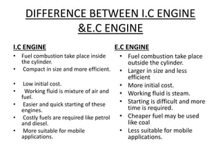
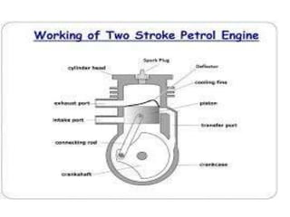
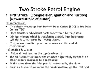
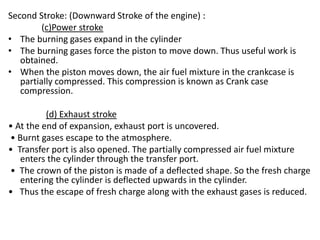
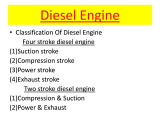
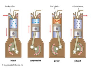
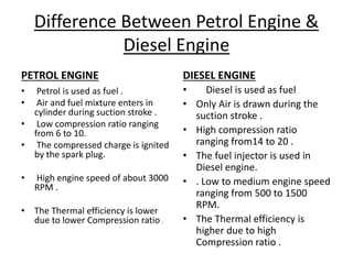
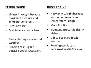
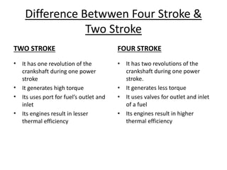
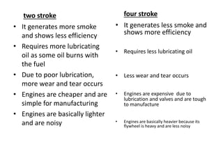
The document provides an overview of internal combustion engines. It defines internal combustion engines as devices that convert the chemical energy of fuel into heat energy and then into mechanical work. It classifies internal combustion engines based on the type of fuel used, thermodynamic cycle, number of strokes, ignition method, cooling method, cylinder arrangement, and engine speed. The document then describes the basic components and functioning of 4-stroke petrol engines, 2-stroke petrol engines, 4-stroke diesel engines, and 2-stroke diesel engines. It highlights the differences between petrol and diesel engines as well as 2-stroke and 4-stroke engines.
The starting system uses a starter motor to engage the engine's flywheel ring gear via a pinion gear, driving the engine at about 200 RPM until it starts. The typical starting system includes a starter motor, magnetic switch, over-running clutch, ignition switch contacts, and park/neutral or clutch start switches. Diagnosis of starting issues involves visual inspections, current draw tests, voltage drop tests, and operational tests to identify electrical or mechanical faults like a dead battery, melted fuse, or loose connections.
Retarders are devices used to boost or replace primary braking systems on heavy vehicles. They help prevent brake fade by reducing reliance on friction brakes for continuous braking. Common types include engine brakes that use compression release to vent air in the cylinders, hydraulic retarders that use fluid drag forces, and electric retarders that use electromagnetic induction to generate opposing magnetic fields and slowing rotation. Retarders help maintain vehicle control and speed and extend the life of primary braking systems.
Automotive Systems course (Module 03) - Fuel Systems in Spark Ignition Intern...Mário Alves
This presentation provides an overview of the fuel systems in Spark Ignition (SI) Internal Combustion Engines, browsing its technological evolution along the years. Spark Ignition engines are the one that need an artificial spark (provided by spark plugs) to ignite (inflame) the air-fuel mixture, such as the ones based on gasoline, alcohol or Liquefied Petroleum Gas (LPG). Diesel engines belong to another class of engines, called "Compression Ignition" (CI) engines.
The ignition system provides a spark to ignite the fuel-air mixture in internal combustion engines. It produces high voltage sparks through an ignition coil to spark plugs in the correct firing order and timing. Electronic ignition systems have replaced mechanical systems and provide more reliable sparking without maintenance of contact points. Different ignition systems use capacitors, transistors or piezo-electric crystals to generate the high voltage spark through different mechanisms. System design considers factors like combustion chamber design, air-fuel ratio, and emissions regulations.
Automotive Systems course (Module 04) - Fuel Systems in Compression Ignition ...Mário Alves
This presentation provides an snapshot of the fuel systems in Compression Ignition (CI) Internal Combustion Engines, browsing its technological evolution along the years. Compression Ignition engines are the ones that do not need an artificial spark to ignite (inflame), as the air-fuel mixture ignites "naturally" resulting from the combination of high temperatures and increasing pressures in the combustion chamber. This is the case of Diesel engines. Gasoline, alcohol or Liquefied Petroleum Gas (LPG) engines belong to another class of engines, called "Spark Ignition" engines.
Automobile Engineering Unit 2 - Anna universitysuresh n
The 2nd unit of automobile engineering describe about carburetor, types of carburetor, ignition system such as coil ignition, magneto ignition and electric ignition system. And also it describe about supercharger and turbocharger
This slides are about inline injection pump and calibration of the pumps .The working of the pump is described in simple words and with examples of daily usable devices.
The document discusses cylinder head and valve train diagnosis and repair. It describes combustion chamber types, steps to recondition a cylinder head, inspecting valve guides, valve types and materials, testing valve springs, and valve rotators. It also covers grinding valve seats, measuring valve stem height, diagnosing cylinder heads, and replacing valve guides. Key terms related to cylinder head and valve components and repair are defined.
THIS PPT IS MAINLY BASED ON HOW THE ELCTRONIC FUEL INJECTION SYSTEMS IN DIFFERENT VEHICLES AND IN THIS WE HAVE DISCUSSED DIFFERENT TECHNIQUES IN DIFFERENT VEHIOCLEWS AND THEIR MODELS ALSO AND THEIR SYSTEMS ALSO IN THE VEHICLES AND THEIR COMPONENTS AND THEIR USES ARE ALSO MENTIONED IN THIS PPT SO IT IS USEFUL FOR BOTH MECHANICAL AND ELECTRONICS STUDENTS
The document summarizes the key components of an internal combustion engine exhaust system. It discusses how exhaust gas is emitted from fuel combustion and transported from the engine through the exhaust manifold. It then describes the three main functions of the exhaust system: to channel waste gases out of the engine; reduce engine noise; and clean emissions. It lists the main pollutants from exhaust and the key components of an exhaust system, which include the exhaust manifold, catalytic converter, muffler, and tail pipe. The exhaust manifold collects hot exhaust gases from the engine and burns any remaining fuel. The catalytic converter uses a catalyst to convert harmful compounds into harmless ones. The muffler then cancels engine noise before the exhaust is expelled through the tail pipe.
This document summarizes key aspects of gasoline direct injection (GDI) engine technology. It discusses the timeline of fuel supply systems from carburetors to port injection to direct injection. The main components of a GDI system are described as the engine control unit, sensors, high pressure fuel pump, and fuel injector. GDI works by directly injecting pressurized fuel into the combustion chamber, allowing for improved efficiency and reduced emissions compared to port fuel injection. Benefits of GDI engines include increased power and torque, reduced fuel consumption and CO2 emissions, and ability to meet future emissions standards.
The document discusses different types of clutches used in vehicles. It describes a clutch as a mechanical device that connects and disconnects two rotating shafts to facilitate transmission of power and motion. The main types discussed are single plate clutches, multi-plate clutches, cone clutches, and centrifugal clutches. A single plate clutch uses a flywheel, pressure plate, clutch disc/plate, and release bearing. A multi-plate clutch has multiple clutch plates to transmit higher torque. A cone clutch uses a cone shape for contact rather than plates. A centrifugal clutch uses centrifugal force from rotation to engage.
This document discusses different fuel injection systems for diesel engines, including air injection systems, solid injection systems, and electronic injection systems. It describes the common rail direct injection (CRDI) system, individual pump system, and distributor system as types of solid fuel injection. The document also covers fuel injection pumps, including the jerk type and distributor type pumps. Finally, it discusses different types of nozzles used in injectors, such as pintle, single hole, multiple hole, and pintaux nozzles.
The ignition system provides a high voltage spark to each spark plug in the correct sequence, igniting the air-fuel mixture. It uses an ignition coil to convert a low voltage current from the battery into a high voltage spark. The components must work together to distribute the spark precisely at the end of the compression stroke for each cylinder. The ignition system turns the engine on and off and ensures reliable sparking over the engine's operating range.
The document discusses diesel engine systems, comparing direct injection (DI) and indirect injection (IDI) engines. It explains that DI engines inject fuel directly into the combustion chamber, while IDI engines inject fuel into a prechamber. The document also describes diesel engine components like the injection pump, injectors, fuel tank, lift pump, and water separator. It explains how diesel engines work through compression ignition and the four strokes of intake, compression, power, and exhaust.
The document discusses the transmission system of automobiles. It defines the transmission system as the mechanism that transmits power from the engine to the driving wheels. The main components of the transmission system are identified as the clutch, gearbox, propeller shaft, universal joints, rear axle, and wheels/tires. The requirements of the transmission system and the types of transmission systems including manual, hydraulic, and automatic are also summarized.
1. The transmission system connects the engine to the wheels through components like the clutch, transmission, transfer case, propeller shaft, differential, and gears.
2. The transmission allows drivers to select between different gear ratios to optimize engine speed and torque based on the vehicle's speed and acceleration needs.
3. Key components include the clutch which connects and disconnects the engine from the transmission, while the transfer case distributes power from the transmission to the front and rear axles for 4-wheel drive vehicles.
The stratified charge engine provides a rich air-fuel mixture near the spark plug for easy ignition using a separate inlet valve. The remainder of the cylinder contains a lean mixture that is ignited by the burning of the rich mixture. This allows the engine to operate with higher compression ratios and leaner mixtures than conventional engines, improving fuel efficiency. Honda introduced the first production stratified charge engine, the CVCC, in 1976, and it used 15-20% less fuel than non-stratified engines of the time.
The document discusses fuel injection systems. It begins with an introduction to fuel injection, noting that it mixes fuel with air and has replaced carburetors. It then describes the construction and working of fuel injection systems, including the fuel injector which injects fuel under high pressure. Different types of fuel injection systems are covered, including multi-point fuel injection and turbocharged direct injection. Advantages are discussed such as increased engine performance, decreased emissions, and increased efficiency. The document concludes that fuel injection and ignition technologies have revolutionized automobiles while allowing for better resource utilization and reduced pollution.
The document describes the main components of an internal combustion engine, including the cylinder head, engine block, pistons, valves, camshaft, crankshaft, connecting rods, and flywheel. It discusses the different types of engines like four-stroke gasoline, two-stroke gasoline, and diesel engines. It also explains the basic functions of engine components like the camshaft converting rotary motion to reciprocating motion and the flywheel reducing vibration and transferring power from the engine.
Multipoint fuel injection (MPFI) systems provide better control of the air-fuel ratio compared to carburetors. MPFI systems use multiple fuel injectors, with one injector per cylinder, to inject fuel into the engine's intake ports or manifold. This allows supplying the optimum air-fuel ratio to each cylinder for all operating conditions. MPFI systems are electronically controlled using sensors to monitor various engine parameters and optimize fuel delivery and emissions performance. While more complex than carburetors, MPFI systems improve fuel efficiency, power, and reduce emissions.
The exhaust system carries away harmful gases produced by the combustion of fuel in the engine. It is comprised of the exhaust manifold, catalytic converter, oxygen sensor, exhaust pipe, and muffler. The gases pass through these components, which work together to reduce noise and emissions. Historically, exhaust systems were made of iron and released more carbon and noise, but modern systems use alloys that are quieter and emit mainly water vapor and carbon dioxide. Future automobiles may increasingly utilize hybrid and electric powertrains.
The document discusses ignition systems and their components. It describes how ignition systems produce a high voltage spark to ignite the air-fuel mixture in each cylinder. The basic components are a battery, ignition switch, ignition coil, switching device, spark plugs and wires. It also covers ignition timing and how it is controlled through mechanisms like the distributor, centrifugal and vacuum advance, and electronic control systems.
Multipoint Fuel Injection System (MPFI)Rutwij Patil
This document discusses fuel injection systems, specifically multiport fuel injection (MPFI) and direct fuel injection (DFI) systems. It provides details on:
- The components and functioning of MPFI systems, including the air intake system, fuel delivery system, and electronic control system. It notes MPFI injects fuel into intake ports.
- The components and functioning of DFI systems, including high pressure fuel rails and injectors located in the cylinder. DFI allows for stratified charge and homogeneous operating modes.
- The advantages of DFI over MPFI, including more complete combustion, better temperature patterns during combustion, and reduced intake duct losses, leading to improved efficiency.
This document provides an overview of common rail direct injection (CRDI) technology for diesel engines. It discusses the history and development of CRDI, the operating principle, key components like the high-pressure pump and fuel rail, and how it works. CRDI allows for more precise fuel injection compared to older direct injection systems, improving power, efficiency and reducing emissions. It sees widespread use in modern passenger vehicles from many automakers. The document also covers the differences between direct and indirect injection, advantages and disadvantages of CRDI, and common applications.
This document discusses the components and operation of carburetors in gasoline engines. It begins by reviewing the different types of carburetors including updraft, horizontal draft, and downdraft configurations. It then explains the basic components and circuits of a simple carburetor including the venturi and float chamber. The document goes on to describe the circuits of a complete carburetor, including the main metering, idling, power enrichment, acceleration pump, and choke circuits. Specific carburetor designs are discussed such as the Solex, Carter, and SU carburetors. The Solex uses a bi-starter for cold starting while the Carter uses multiple jets and an accelerator pump. The SU carb
The document provides an introduction to internal combustion engines. It discusses the basic differences between internal and external combustion engines and classifications of internal combustion engines based on fuel, cycle of operation, and combustion process. It then describes the basic parts and working principles of 4-stroke petrol and diesel engines as well as 2-stroke petrol engines. Key differences between petrol and diesel engines are also highlighted. The document concludes by defining common terminology used in internal combustion engines.
This document provides an introduction to internal combustion engines, including their basic components and classifications. It discusses the four main components of heat engines and describes the four stroke cycles of both gasoline and diesel engines. It also summarizes the differences between two-stroke and four-stroke engines as well as spark ignition and compression ignition engines. The key points covered are: the basic operation and components of IC engines, the thermodynamic cycles that heat engines rely on to convert heat to work, the differences between 2-stroke and 4-stroke engine cycles, and classifications of IC engines based on ignition type, valve arrangement, cooling method and more.
The document provides an overview of heat engines and internal combustion engines. It defines heat engines as machines that convert heat energy into mechanical energy through combustion. Internal combustion engines are heat engines where combustion occurs inside the engine cylinder. The key components and terminology of internal combustion engines are described. The four stroke cycle of spark ignition engines and compression ignition engines is summarized. Two stroke engines that complete the cycle in two strokes are also introduced. Examples calculating engine specifications like displacement, clearance volume, and compression ratio are included.
This document summarizes the key components and operation of internal combustion engines. It discusses:
- The definitions of engines and heat engines and classifications of engines as rotary, reciprocating, external combustion, and internal combustion.
- The major components of engines like the cylinder, piston, combustion chamber, valves, and their functions.
- The operating cycles of 4-stroke spark ignition engines and 4-stroke compression ignition engines through their intake, compression, combustion, and exhaust strokes.
- Comparisons between spark ignition and compression ignition engines and between 2-stroke and 4-stroke engines.
- Differences between ideal engine diagrams and actual engine performance.
This document provides information on internal combustion engines, including:
1. It defines internal combustion engines and classifies them based on where combustion occurs, fuel used, thermodynamic cycle, number of strokes, ignition method, cooling method, and more.
2. It describes the basic components of an IC engine like the cylinder block, cylinder head, piston, connecting rod, crankshaft, and camshaft.
3. It explains the four strokes of a typical four-stroke engine cycle and compares it to the two-stroke engine cycle.
1. INTRODUCTION TO IC ENGINE
2. FUNDAMENTALS OF IC ENGINE
3. CONSTRUCTIONAL FEATURES & FUNCTIONS OF IC ENGINE
4. MATERIALS USED
5.IC ENGINE – TERMINOLOGY
6.SEQUENCE OF OPERATION(A. Four Stroke Engine/B. Two Stroke Engine)
7. COMPARISON BETWEEN TWO STROKE AND FOUR STROKE ENGINES
8.Otto Cycle,Diesel Cycle,Dual Cycle & their Comparison
9.VALVE TIMING DIAGRAM
10.ENGINE PERFORMANCE PARAMETERS RELATED TO IC ENGINE
11. CHARACTERISTICS CURVES OF VARIOUS PERFORMANCE PARAMETERS
12. FUEL-AIR CYCLE & THEIR ANALYSIS ( 1.Brake Specific Fuel Consumption vs Size 2. Brake Specific Fuel Consumption vs Speed 3. Performance Maps )
13. ACTUAL INDICATOR DIAGRAM
14. V.C.R ENGINE SPECIFICATIONS & ITS DESCRIPTION
15. FUTURE WORKS & DISCUSSION
16. CONCLUSION
This document provides an overview of internal combustion engines and gas turbines presented by Subhojit Das. It discusses the construction and 2-stroke process of a 2-stroke CI (compression ignition/diesel) engine. The 2-stroke CI engine uses piston movements to generate power in two strokes by compressing air, injecting and igniting fuel, and exhausting gases. The construction includes a cylinder with inlet, exhaust, and transfer ports that open and close based on piston movement. The 2-stroke process involves air suction and compression on the upstroke, followed by power expansion and exhaust on the downstroke, using the transfer port to scavenge exhaust with fresh air. Losses in the 2-stroke engine include
The main components of a steam power plant are a boiler, turbine, condenser, cooling tower, and pump. The Rankine cycle consists of four processes: (1) isentropic compression in the boiler, (2) isobaric heating in the boiler, (3) isentropic expansion in the turbine, and (4) isobaric cooling in the condenser. Heat added in the boiler is converted to work output by the turbine, which is then used to run a generator. The vapor from the turbine is condensed back into a liquid in the condenser and pumped back to the boiler to repeat the cycle.
The document provides information on types of heat engines, including internal and external combustion engines. It then discusses key components of internal combustion (IC) engines like the cylinder block, cylinder head, piston, combustion chamber, camshaft, valves, piston rings, connecting rod, crankshaft, and flywheel. It also defines 4-stroke engines and compares spark ignition (SI) and compression ignition (CI) engines. Finally, it explains the construction and working of 4-stroke petrol/diesel engines and 2-stroke petrol/diesel engines through their intake, compression, power/expansion, and exhaust strokes.
This document provides an overview of four-stroke and two-stroke engines. It describes the four strokes of a four-stroke engine: intake, compression, power, and exhaust. It also outlines the two strokes of a two-stroke engine: the intake/combustion stroke and the expansion/exhaust stroke. The document compares key aspects of four-stroke and two-stroke engines such as the number of rotations required to complete a cycle, how power is produced, and design complexity. It provides details on the function and timing of valves and ports during each stroke.
this is the ppt on 2 stroke and 4 stroke petrol engine. . i made this ppt with the help of dhrumil patel .who is in the L.D. college of engineering in chemical department. . i am very thankful to him for being my great partner. . .thanx dhrumil..
1. The document discusses different types of heat engines including internal combustion (IC) engines and external combustion engines. IC engines are further classified based on their cycle of operation, thermodynamic cycle, type of fuel used, ignition method, cooling system, and valve location.
2. The main components of an IC engine are described including the cylinder block, cylinder head, piston, connecting rod, crankcase, and others. Additionally, the construction and working of four-stroke petrol engines, four-stroke diesel engines, and two-stroke engines are explained.
The document outlines the contents of a presentation on internal combustion engines. It includes sections on the introduction and classification of I.C. engines, components of I.C. engines, terminology used, and descriptions of the four stroke cycles of petrol and diesel engines. The key components of I.C. engines such as the cylinder, piston, crankshaft, valves and manifolds are defined. Advantages and disadvantages are provided for four stroke petrol and diesel engines.
ic Engine and reciprocating machine ch1.pdfTsegayePaulos1
The document provides an overview of internal combustion (IC) engines and their components. It discusses how IC engines work and are classified. Specifically, it notes that IC engines convert the chemical energy of fuel into thermal energy and use this to produce mechanical work. It also outlines the basic components of IC engines like the cylinder block, cylinder head, pistons, valves/ports, camshaft, crankshaft, and connecting rod. Furthermore, it explains the four stroke cycle of intake, compression, power, and exhaust strokes and compares it to the two stroke cycle which completes the process in two strokes. Terminology used in IC engines is also defined.
Internal Combustion Engine
There are two main types of heat engines: internal combustion engines and external combustion engines. In an internal combustion engine, fuel combustion occurs inside the engine cylinder and the hot gases directly power the piston. This includes gasoline/petrol engines. The four strokes of a petrol engine are: intake, compression, power, and exhaust. In the intake stroke, air/fuel mixture enters the cylinder. In the compression stroke, the mixture is compressed. In the power stroke, combustion powers the piston. In the exhaust stroke, spent gases are pushed out.
This document provides an overview of internal combustion (IC) engines, including:
- The main types of IC engines are reciprocating and rotary engines, classified by working cycle as Otto or diesel cycle engines, and by strokes as two-stroke or four-stroke engines.
- Four-stroke engines complete their cycle over two revolutions of the crankshaft, with intake, compression, power, and exhaust strokes. In a four-stroke SI engine, an air-fuel mixture is drawn in and compressed before being ignited by a spark plug.
- Four-stroke diesel engines operate at higher compression ratios than gasoline engines, igniting injected fuel without a spark plug due to high compression temperatures.
This document discusses the two-stroke engine cycle. It provides a brief history of the two-stroke engine and explains the key differences from a four-stroke engine. The two-stroke cycle combines the intake, compression, power, and exhaust strokes into only two piston strokes. Diagrams show the opening and closing of the intake and exhaust valves through the two strokes. The expansion and compression strokes are described in more detail. Valve timing diagrams for two-stroke petrol and diesel engines are also presented.
The document discusses the main components and working principle of a diesel generator. A diesel generator combines a diesel engine with an electric generator and other auxiliary devices to generate electrical energy. It works by converting the chemical energy of fuel into thermal energy, then mechanical energy through the combustion and expansion of gases in the engine, which is then converted into electrical energy through the generator via electromagnetic induction. The key components are the diesel engine, generator, and auxiliary devices like the cooling system. The diesel engine uses compression ignition to burn fuel injected into the combustion chamber.
It contains Working, Construction of 4 stroke petrol engine with PV Diagram and Advantages & Disadvantages.Very useful & all info compiled at same place.
Advanced control scheme of doubly fed induction generator for wind turbine us...IJECEIAES
This paper describes a speed control device for generating electrical energy on an electricity network based on the doubly fed induction generator (DFIG) used for wind power conversion systems. At first, a double-fed induction generator model was constructed. A control law is formulated to govern the flow of energy between the stator of a DFIG and the energy network using three types of controllers: proportional integral (PI), sliding mode controller (SMC) and second order sliding mode controller (SOSMC). Their different results in terms of power reference tracking, reaction to unexpected speed fluctuations, sensitivity to perturbations, and resilience against machine parameter alterations are compared. MATLAB/Simulink was used to conduct the simulations for the preceding study. Multiple simulations have shown very satisfying results, and the investigations demonstrate the efficacy and power-enhancing capabilities of the suggested control system.
Literature Review Basics and Understanding Reference Management.pptxDr Ramhari Poudyal
Three-day training on academic research focuses on analytical tools at United Technical College, supported by the University Grant Commission, Nepal. 24-26 May 2024
Electric vehicle and photovoltaic advanced roles in enhancing the financial p...IJECEIAES
Climate change's impact on the planet forced the United Nations and governments to promote green energies and electric transportation. The deployments of photovoltaic (PV) and electric vehicle (EV) systems gained stronger momentum due to their numerous advantages over fossil fuel types. The advantages go beyond sustainability to reach financial support and stability. The work in this paper introduces the hybrid system between PV and EV to support industrial and commercial plants. This paper covers the theoretical framework of the proposed hybrid system including the required equation to complete the cost analysis when PV and EV are present. In addition, the proposed design diagram which sets the priorities and requirements of the system is presented. The proposed approach allows setup to advance their power stability, especially during power outages. The presented information supports researchers and plant owners to complete the necessary analysis while promoting the deployment of clean energy. The result of a case study that represents a dairy milk farmer supports the theoretical works and highlights its advanced benefits to existing plants. The short return on investment of the proposed approach supports the paper's novelty approach for the sustainable electrical system. In addition, the proposed system allows for an isolated power setup without the need for a transmission line which enhances the safety of the electrical network
Understanding Inductive Bias in Machine LearningSUTEJAS
This presentation explores the concept of inductive bias in machine learning. It explains how algorithms come with built-in assumptions and preferences that guide the learning process. You'll learn about the different types of inductive bias and how they can impact the performance and generalizability of machine learning models.
The presentation also covers the positive and negative aspects of inductive bias, along with strategies for mitigating potential drawbacks. We'll explore examples of how bias manifests in algorithms like neural networks and decision trees.
By understanding inductive bias, you can gain valuable insights into how machine learning models work and make informed decisions when building and deploying them.
Embedded machine learning-based road conditions and driving behavior monitoringIJECEIAES
Car accident rates have increased in recent years, resulting in losses in human lives, properties, and other financial costs. An embedded machine learning-based system is developed to address this critical issue. The system can monitor road conditions, detect driving patterns, and identify aggressive driving behaviors. The system is based on neural networks trained on a comprehensive dataset of driving events, driving styles, and road conditions. The system effectively detects potential risks and helps mitigate the frequency and impact of accidents. The primary goal is to ensure the safety of drivers and vehicles. Collecting data involved gathering information on three key road events: normal street and normal drive, speed bumps, circular yellow speed bumps, and three aggressive driving actions: sudden start, sudden stop, and sudden entry. The gathered data is processed and analyzed using a machine learning system designed for limited power and memory devices. The developed system resulted in 91.9% accuracy, 93.6% precision, and 92% recall. The achieved inference time on an Arduino Nano 33 BLE Sense with a 32-bit CPU running at 64 MHz is 34 ms and requires 2.6 kB peak RAM and 139.9 kB program flash memory, making it suitable for resource-constrained embedded systems.
CHINA’S GEO-ECONOMIC OUTREACH IN CENTRAL ASIAN COUNTRIES AND FUTURE PROSPECTjpsjournal1
The rivalry between prominent international actors for dominance over Central Asia's hydrocarbon
reserves and the ancient silk trade route, along with China's diplomatic endeavours in the area, has been
referred to as the "New Great Game." This research centres on the power struggle, considering
geopolitical, geostrategic, and geoeconomic variables. Topics including trade, political hegemony, oil
politics, and conventional and nontraditional security are all explored and explained by the researcher.
Using Mackinder's Heartland, Spykman Rimland, and Hegemonic Stability theories, examines China's role
in Central Asia. This study adheres to the empirical epistemological method and has taken care of
objectivity. This study analyze primary and secondary research documents critically to elaborate role of
china’s geo economic outreach in central Asian countries and its future prospect. China is thriving in trade,
pipeline politics, and winning states, according to this study, thanks to important instruments like the
Shanghai Cooperation Organisation and the Belt and Road Economic Initiative. According to this study,
China is seeing significant success in commerce, pipeline politics, and gaining influence on other
governments. This success may be attributed to the effective utilisation of key tools such as the Shanghai
Cooperation Organisation and the Belt and Road Economic Initiative.
Optimizing Gradle Builds - Gradle DPE Tour Berlin 2024Sinan KOZAK
Sinan from the Delivery Hero mobile infrastructure engineering team shares a deep dive into performance acceleration with Gradle build cache optimizations. Sinan shares their journey into solving complex build-cache problems that affect Gradle builds. By understanding the challenges and solutions found in our journey, we aim to demonstrate the possibilities for faster builds. The case study reveals how overlapping outputs and cache misconfigurations led to significant increases in build times, especially as the project scaled up with numerous modules using Paparazzi tests. The journey from diagnosing to defeating cache issues offers invaluable lessons on maintaining cache integrity without sacrificing functionality.
Comparative analysis between traditional aquaponics and reconstructed aquapon...bijceesjournal
The aquaponic system of planting is a method that does not require soil usage. It is a method that only needs water, fish, lava rocks (a substitute for soil), and plants. Aquaponic systems are sustainable and environmentally friendly. Its use not only helps to plant in small spaces but also helps reduce artificial chemical use and minimizes excess water use, as aquaponics consumes 90% less water than soil-based gardening. The study applied a descriptive and experimental design to assess and compare conventional and reconstructed aquaponic methods for reproducing tomatoes. The researchers created an observation checklist to determine the significant factors of the study. The study aims to determine the significant difference between traditional aquaponics and reconstructed aquaponics systems propagating tomatoes in terms of height, weight, girth, and number of fruits. The reconstructed aquaponics system’s higher growth yield results in a much more nourished crop than the traditional aquaponics system. It is superior in its number of fruits, height, weight, and girth measurement. Moreover, the reconstructed aquaponics system is proven to eliminate all the hindrances present in the traditional aquaponics system, which are overcrowding of fish, algae growth, pest problems, contaminated water, and dead fish.
The CBC machine is a common diagnostic tool used by doctors to measure a patient's red blood cell count, white blood cell count and platelet count. The machine uses a small sample of the patient's blood, which is then placed into special tubes and analyzed. The results of the analysis are then displayed on a screen for the doctor to review. The CBC machine is an important tool for diagnosing various conditions, such as anemia, infection and leukemia. It can also help to monitor a patient's response to treatment.
2. OUTLINE
• Introduction
• Classification of I.C. engines ,
• Engine details,
• I.C.Engine terminology ,
• Four stroke petrol Engine ,
• Two stroke petrol Engine ,
• Four stroke petrol Engine,
• Two stroke diesel Engine,
• Difference between petrol engine and diesel engine ,
• Difference between two stroke and four stroke cycle
engines ,
3. INTRODUCTION
• Engine refers as “Heat engine is a device which
converts chemical energy of fuel into Heat energy
and this Heat energy further convert into
mechanical work”.
• Based on where the combustion of fuel take
place. Whether outside the working cylinder or
inside the working cylinder
• (a) External combustion engines (E.C.ENGINES),
• (b) Internal combustion engines (I.C.ENGINES)
4. DIFFERENCE BETWEEN I.C ENGINE
&E.C ENGINE
I.C ENGINE
• Fuel combustion take place inside
the cylinder.
• Compact in size and more efficient.
• Low initial cost.
• Working fluid is mixture of air and
fuel.
• Easier and quick starting of these
engines.
• Costly fuels are required like petrol
and diesel.
• More suitable for mobile
applications.
E.C ENGINE
• Fuel combustion take place
outside the cylinder.
• Larger in size and less
efficient
• More initial cost.
• Working fluid is steam.
• Starting is difficult and more
time is required.
• Cheaper fuel may be used
like coal
• Less suitable for mobile
applications.
5. CLASSIFICATION OF I.C ENGINE
I.C.ENGINES are may be classified according to
• Type of fuel used as (1)Petrol engine (2)Diesel engine (3)Gas engines (4)Bi-fuel
engine (two fuel engine)
• Nature of thermodynamic cycle as: (1)Otto cycle engine (2)Diesel engine cycle (3)
Duel or mixed cycle engine
• Number of stroke per cycle as : (1) Four stroke engine (2) Two stroke engine
• Method of ignition as : (1) Spark Ignition engines (Mixture of air and fuel is ignited
by electric spark) (2) Compression Ignition engines (The fuel is ignited as it comes
in contact with hot Compressed air)
• Method of Cooling as : (1) Air cooled engines (2) Water cooled engines
• Speed of the engines as : (1) Low speed engines (2) Medium speed engines (3)
High speed engines
• Number of cylinder as : (1) Single cylinder engines (2) Multi cylinder engines
• Position of the cylinder as : (1) Inline engines (2) V-engines (3) Radial engines (4)
Opposed cylinder engines
6.
7. ENGINE TERMINOLOGY
The standard terms used in I.C Engines are
1. Bore: Inside diameter of the cylinder is termed as Bore.
2. Top Dead Center (TDC): The extreme position reached by
the piston at the top of the cylinder in the vertical engine is
called Top Dead center.
3. Bottom Dead Center (BDC): The extreme position reached
by the piston at the Bottom of the cylinder in the vertical
engine is called Bottom Dead center.
4. Stroke: The nominal distance travelled by the piston in the
cylinder between the extreme upper and lower positions of
the piston (TDC &BDC) is termed as stroke.
5. Compression ratio (r): It is the ratio of Maximum cylinder
volume to the Clearance volume
8. 6. Cylinder volume (v): It is the sum of swept
volume and the Clearance volume.
V = Vs + Vc
7. Swept volume (Vs): It is the volume of space
generated by the movement of piston from
one dead center to another dead center.
8. Clearance Volume(Vc): It is the space in the
cylinder, when the piston is at Top Dead
Center
9. PETROL ENGINE
Classification of Petrol Engines
•Four Stroke cycle Petrol Engines
(1)Intake (suction stroke)
(2)Compression
(3)Power(Expansion stroke)
(4)Exhaust
•Two Stroke cycle petrol Engines
(1)Power &Exhaust
(2)Intake &Compression
10.
11. Four Stroke Petrol Engine
(a) Suction Stroke (First Stroke of the Engine)
• Piston moves down from TDC to BDC
• Inlet valve is opened and the exhaust valve is closed.
• Pressure inside the cylinder is reduced below the
atmospheric pressure.
• The mixture of air fuel is sucked into the cylinder through
the inlet valve .
(b) Compression Stroke : (Second Stroke of the piston)
• Piston moves up from BDC to TDC
• Both inlet and exhaust valves are closed.
• The air fuel mixture in the cylinder is compressed.
12. (c) Power or Expansion Stroke: (Third Stroke of the Engine)
• The burning gases expand rapidly. They exert an impulse (thrust or
force) on the piston. The piston is pushed from TDC to BDC
• This movement of the piston is converted into rotary motion of the
crankshaft through connecting rod.
• Both inlet and exhaust valves are closed.
(d) Exhaust Stroke (Fourth stroke of the piston)
• Piston moves upward from BDC
• Exhaust valve is opened and the inlet valve is closed.
• The burnt gases are forced out to the atmosphere through the
exhaust valve (Some of the burnt gases stay in the clearance
volume of the cylinder)
• The exhaust valve closes shortly after TDC
• The inlet valve opens slightly before TDC and the cylinder is ready
to receive fresh charge to start a new cycle.
13.
14. Two Stroke Petrol Engine
• First Stroke : (Compression, ignition and suction)
(Upward stroke of piston)
(a) compression:
• The piston moves up from Bottom Dead Centre (BDC) to Top Dead
Centre (TDC)
• Both transfer and exhaust ports are covered by the piston.
• Air fuel mixture which is transferred already into the engine
cylinder is compressed by moving piston.
• The pressure and temperature increases at the end of
compression.
(b) Ignition & Suction
• Piston almost reaches the top dead centre
• The air fuel mixture inside the cylinder is ignited by means of an
electric spark produced by a spark plug
• At the same time, the inlet port is uncovered by the plane.
• Fresh air fuel mixture enters the crankcase through the inlet port
15. Second Stroke: (Downward Stroke of the engine) :
(c)Power stroke
• The burning gases expand in the cylinder
• The burning gases force the piston to move down. Thus useful work is
obtained.
• When the piston moves down, the air fuel mixture in the crankcase is
partially compressed. This compression is known as Crank case
compression.
(d) Exhaust stroke
• At the end of expansion, exhaust port is uncovered.
• Burnt gases escape to the atmosphere.
• Transfer port is also opened. The partially compressed air fuel mixture
enters the cylinder through the transfer port.
• The crown of the piston is made of a deflected shape. So the fresh charge
entering the cylinder is deflected upwards in the cylinder.
• Thus the escape of fresh charge along with the exhaust gases is reduced.
16. Diesel Engine
• Classification Of Diesel Engine
Four stroke diesel engine
(1)Suction stroke
(2)Compression stroke
(3)Power stroke
(4)Exhaust stroke
Two stroke diesel engine
(1)Compression & Suction
(2)Power & Exhaust
17.
18. Four Stroke Diesel Engine
(a) Suction Stroke (First Stroke of the piston)
• Piston moves from TDC to BDC
• Inlet valve is opened and the exhaust valve is closed.
• The pressure inside the cylinder is reduced below the
atmospheric pressure.
• Fresh air from the atmosphere is sucked into the engine
cylinder through air cleaner and inlet valve.
(b) Compression stroke (Second stroke of the piston)
• Piston moves from BDC to TDC
• Both inlet and exhaust valves are closed.
• The air is drawn during suction stroke is compressed to a
high pressure and temperature
19. (c) power stroke (Third stroke of the piston)
• The burning gases (products of combustion) expand rapidly.
• The burning gases push the piston move downward from
TDC to BDC
• This movement of piston is converted into rotary motion of
the crank shaft through connecting rod.
• Both inlet and exhaust valves are closed.
(d) Exhaust Stroke (Fourth stroke of the piston)
• Piston moves from BDC to TDC
• Exhaust valve is opened the inlet valve is closed.
• The burnt gases are forced out to the atmosphere through
the exhaust valve. (some of the burnt gases stay in the
clearance volume of the cylinder)
• The exhaust valve closes shortly after TDC
• The inlet valve opens slightly before TDC and the cylinder is
ready to receive fresh air to start a new cycle.
20. Two Stroke Diesel Engine
• First Stroke : (Compression, ignition and suction) (Upward stroke of piston)
(a) compression stroke:
•. The piston moves upwards from Bottom Dead Centre (BDC) to Top Dead Centre
(TDC).
• Both transfer and exhaust ports are covered.
• Air which is transferred already into the engine cylinder is compressed by
moving piston.
• The pressure and temperature of the air increases.
• At the same time, fresh air is admitted into the crankcase
(b) Suction stroke:
•Piston almost reaches the top dead centre.
• The fuel is injected into the hot compressed air inside the cylinder. The fuel
mixed with hot air and burns.
• The admission of fresh air into the crankcase continues till the piston reaches
the top centre.
21. (c)Power stroke
• The burning gases expand in the cylinder.
•Burning gases force the piston to move down. Thus useful work is
obtained.
•At the same time, the air in the crank case is compressed by the
movement of the piston.
•All the ports are in closed position
(d) Exhaust Stroke :
• At the end of expansion, the exhaust port is uncovered.
•The burnt escape to the atmosphere through the exhaust port.
•Transfer port is also uncovered shortly after the exhaust port is
opened.
•The partially compressed air from crank case enters the cylinder the
transfer port.
•This air is deflected upwards by the deflected shape of the piston.
•Thus the entering air helps in forcing out the combustion products
from the cylinder
22. Difference Between Petrol Engine &
Diesel Engine
PETROL ENGINE
• Petrol is used as fuel .
• Air and fuel mixture enters in
cylinder during suction stroke .
• Low compression ratio ranging
from 6 to 10.
• The compressed charge is ignited
by the spark plug.
• High engine speed of about 3000
RPM .
• The Thermal efficiency is lower
due to lower Compression ratio .
DIESEL ENGINE
• Diesel is used as fuel
• Only Air is drawn during the
suction stroke .
• High compression ratio
ranging from14 to 20 .
• The fuel injector is used in
Diesel engine.
• . Low to medium engine speed
ranging from 500 to 1500
RPM.
• The Thermal efficiency is
higher due to high
Compression ratio .
23. PETROL ENGINE
• Lighter in weight because
maximum pressure and
Temperature is less .
• Less Costlier .
• Maintanence cost is Less .
• Easier starting even in cold
weather .
• Running cost Higher
because petrol is Costlier .
DIESEL ENGINE
• Heavier in Weight because
maximum pressure and
temperature is high .
• More Costlier .
• Maintanence cost is Slightly
higher .
• Difficult to start in cold
weather
• Running cost is Less
because diesel is Cheaper .
24. Difference Betwwen Four Stroke &
Two Stroke
TWO STROKE
• It has one revolution of the
crankshaft during one power
stroke
• It generates high torque
• Its uses port for fuel’s outlet and
inlet
• Its engines result in lesser
thermal efficiency
FOUR STROKE
• It has two revolutions of the
crankshaft during one power
stroke.
• It generates less torque
• It uses valves for outlet and inlet
of a fuel
• Its engines result in higher
thermal efficiency
25. two stroke
• It generates more smoke
and shows less efficiency
• Requires more lubricating
oil as some oil burns with
the fuel
• Due to poor lubrication,
more wear and tear occurs
• Engines are cheaper and are
simple for manufacturing
• Engines are basically lighter
and are noisy
four stroke
• It generates less smoke and
shows more efficiency
• Requires less lubricating oil
• Less wear and tear occurs
• Engines are expensive due to
lubrication and valves and are tough
to manufacture
• Engines are basically heavier because its
flywheel is heavy and are less noisy