Download to read offline


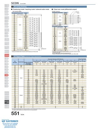
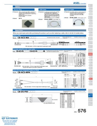
![PS-24 Controller
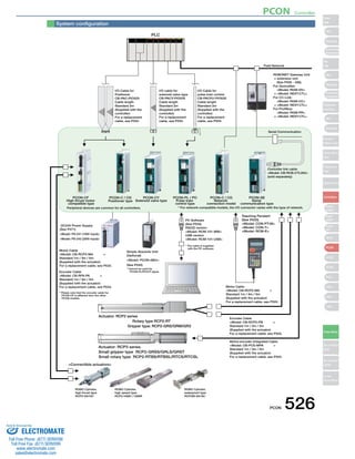
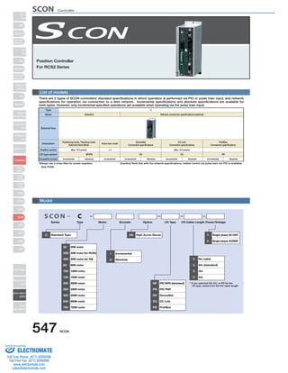
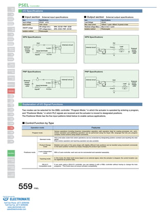
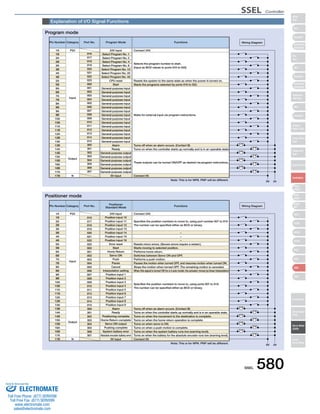
PS-24
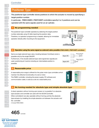
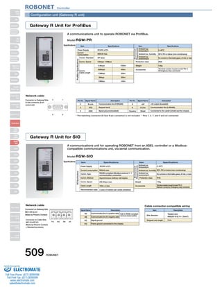
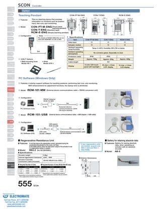
■ Model PS-241/PS-242
DC24V Power supply for ROBO Cylinder
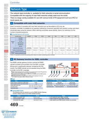
1 Maximum Momentary Output of 17A
Up to 17A of maximum momentary output current is possible at 8.5A
rated output current. This lets you select an appropriate power-supply
capacity based on the total rated current of actuators,
without having to consider the maximum momentary current that
may be generated by the actuators during acceleration. Because you
no longer need to use an expensive high-capacity power supply,
cost can be reduced substantially.
* The maximum momentary output current must be considered if the actuator operating
conditions are tight. See the “Selection Guide” at right for details.
2 Parallel Operation Enabled
Up to 5 units can be operated in parallel.
Therefore, even if the power capacity is
insufficient with one unit, this can be easily
remedied by adding one unit, without the
need to replace the unit with a larger
capacity power supply.
3 Load Detection Function
Load percentage can be detected by
the RDY (Ready) display lamp and
the RDY output signal.
Table 1. PS-24 Rated Current and Allowable Maximum Momentary Electric Current
471 PS-24
When selecting a power-supply unit for operating multiple actuators, normally a
unit with a capacity equal to or exceeding the total maximum current of all
actuators is chosen. However, actuators generate their maximum current only
momentarily during acceleration, etc., and in many cases the power-supply is
over-specified.
On the other hand, the PS-24 power supply provides the following advantages:
1. Supporting maximum momentary current of up to twice the rated current.
2. If you need more power-supply capacity, you can simply add an extra unit or units.
The above features let you select an optimal power-supply capacity.
Number of Power-Supply Units
Basically, how many power-supply units you need should be determined in such a
way that the total rated current of all actuators will remain within the rated current
of the PS-24. If the load condition is tight, however, the power-supply capacity may
still become inadequate. In such cases, add an extra power supply or supplies.
“Severe load conditions” refers to:
Large load (load is approaching the rated load capacity)
No. of Connected units
High acceleration/deceleration
High speed
Simultaneous operation of multiple axes
Use of the RCS2-SRA7 series (Structurally these actuators allow maximum
current to flow for a longer period).
Table 2. Actuator vs. Power Supply Current
Rated current [A] Max. momentary current [A]
Controller Type Actuator Type
ERC2 ERC2
Note: For the second and subsequent units, add a 10% safety buffer (loss). *1
Selection target Number of actuators connected
PSEP
RPCON
PCON
PCON-CF
ASEP
RACON
ACON
All models of RCP3/RCP2
(* Excluding the 5 models below)
RCP2-HS8C / RCP2-HS8R
RCP2-RA10C
RCP2W-RA10C / RCP2W-SA16C
Rated
(=Maximum)
Rated
(=Maximum)
2 8 8
6 2 2
Rated 1.3
3
4
3
3
4
6
6
5
6
6
SA4, SA5 (20W)
Number of Connectible Units
for PS-24 (Reference)*1
If the servo is
on for all axes
simultaneously
If the servo is
NOT on for all
axes simultaneously
Power supply
current [A]
SA6 (30W)
RA3 (20W)
RA4 (20W)
RA4 (30W)
Maximum
Rated
Maximum
Rated
Maximum
Rated
Maximum
Rated
Maximum
4.4
1.3
4
1.7
5.1
1.3
4.4
1.3
4
1
2
3
4
5
8.5
15.3
22.95
30.6
38.25
17
30.6
45.9
61.2
76.5
The figures in “Number of Connectable Units for PS-24 (Reference)” are calculated based on the
following: When supplying power to multiple controllers, make sure that the sum of the rated current
for the individual axes stays LOWER than the PS-24’s rated current (8.5A). Exceptions: For
RCP3/RCP2/RCP2W, make sure that the sum of the rated current for the individual axes is LOWER
than the PS-24’s maximum momentary current (17A).
For PSEL/ASEL, this varies with number of axes used and the model. Please ask for details.
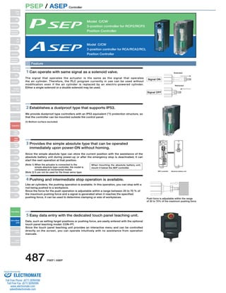
Features
Names
Power supply1 Power supply2 Power supply5
Load
RDY display
RDY output
1 Ready indicating light (RDY)
2 Level setting dial for over load detection
(LF.DET)
* Appropriate value settled at shipment. Operation not
needed.
3 Ready output signal (RDYOUT)
4 5 + 24V Output terminal ( + 24V)
*45 connected internally.
6 7 0V Output terminal (0V)
*67 connected internally.
8 Frame ground terminal (FG)
Terminal for ground.
9 AC input terminal (AC (N))
10 AC input terminal (AC100V) (AC100 (L))
11 AC input terminal (AC200V) (AC200 (L))
* AC100V input type should be connected to 9 and 0
interval, AC200V to9 andA. Unavailable for
combined use.
3
4
5
6
7
8
9
10
11
2 1
Slider
Type
Mini
Standard
Controllers
Integrated
Rod
Type
Mini
Standard
Controllers
Integrated
Table/Arm
/Flat Type
Mini
Standard
Gripper/
Rotary Type
Linear Servo
Type
Cleanroom
Type
Splash-Proof
Controllers
PMEC
/AMEC
PSEP
/ASEP
ROBO
NET
ERC2
PCON
ACON
SCON
PSEL
ASEL
SSEL
XSEL
Pulse Motor
Servo Motor
(24V)
Servo Motor
(200V)
Linear
Servo Motor
Sold & Serviced By:
ELECTROMATE
Toll Free Phone (877) SERVO98
Toll Free Fax (877) SERV099
www.electromate.com
sales@electromate.com](https://image.slidesharecdn.com/iairobocylindercontrollercatalog-141015195025-conversion-gate02/85/Iai-robo-cylinder_controller_catalog-11-320.jpg)
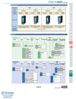
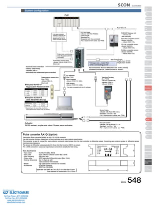
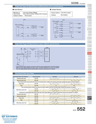
![PS-24 Controller
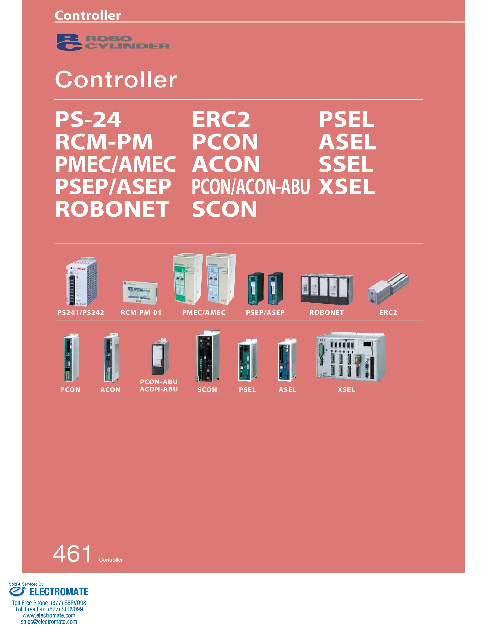
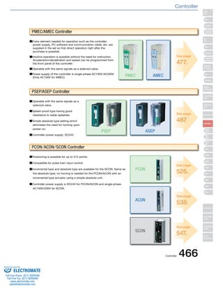
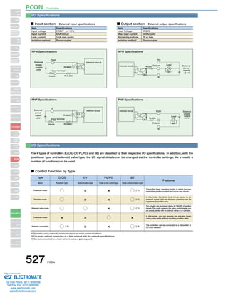
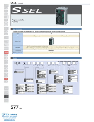
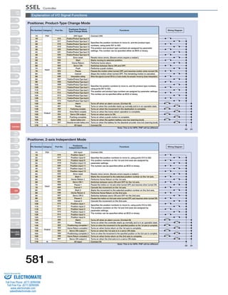
PS-24 472
List of Models
Specification List
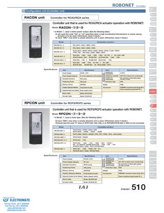
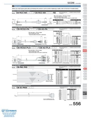
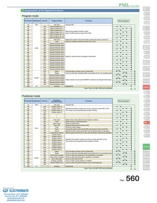
Item
Rated DC output voltage
Rated DC output current
Instantaneous max. output current
Rated output capacity
Efficiency
Rated input (frequency)
Input voltage range
Input current
Output holding time
Protection circuit
Parallel operation
Operating temperature
Operating humidity
Cooling method
Voltage resistance
Insulation resistance
Circuit method
Weight
Outer dimensions
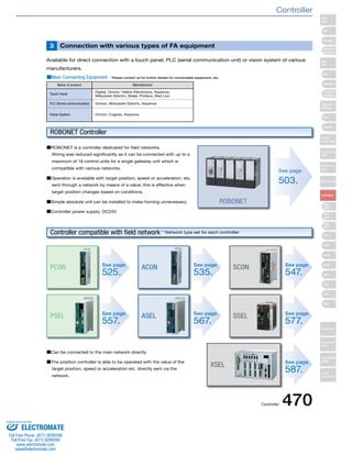
PS-241 PS-242
24V±10% (varied depending on the load)
8.5A
17A
204W
80% 80%
AC100~115V (50/60Hz) AC200~230V (50/60Hz)
AC85~125V AC170~250V
3.50A (100VAC full load) 1.80A (200VAC full load)
20 [msec] (Ambient temperature 25ºC under rated input/output condition)
Protection from overcurrent, overvoltage, overheating and overload.
Possible
0~50ºC (derated)
30~85%RH (non-condensing)
Natural, air cooling
Between input/output···2.0kVA per minute (20mA)
Between cabinets···2.0kVA per minute (20mA)
Output - 100MΩ or more between cabinets at 500 VDC
Separate excitation type flyback converter
Aprox. 0.9kg
31.5 33
5
64.5
31.5 33
ø5 (for mounting)
10 138 10
R2. 5 (for mounting)
10 8
5 148±0.5 5
158
13
M3.5 screw terminal
139.7
DC24V Power Supply
PS-24
Caution:
• The PS-24 is not a constant voltage power supply. The output voltage changes with the load (voltage decreases according to the
load percentage). Therefore, do not connect any equipment other than ROBO Cylinder actuators.
• Up to 5 units can be operated in parallel. Do not use any power supplies other than the PS-24 at the same time for parallel operation.
• Note that serial operations are not possible.
• As a rule, when operating multiple units in a row, allow at least 20mm space between each power supply.
• This is a natural air-cooled power supply. Please give due consideration to natural convection so that heat does not build up around
the power supply.
• The case of this product also has heat a dissipating effect. Do not touch the case after installation as it may result in severe burns.
Model
Standard Price
PS-241 PS-242
− −
Slider
Type
Mini
Standard
Controllers
Integrated
Rod
Type
Mini
Standard
Controllers
Integrated
Table/Arm
/Flat Type
Mini
Standard
Gripper/
Rotary Type
Linear Servo
Type
Cleanroom
Type
Splash-Proof
Controllers
PMEC
/AMEC
PSEP
/ASEP
ROBO
NET
ERC2
PCON
ACON
SCON
PSEL
ASEL
SSEL
XSEL
Pulse Motor
Servo Motor
(24V)
Servo Motor
(200V)
Linear
Servo Motor
Sold & Serviced By:
ELECTROMATE
Toll Free Phone (877) SERVO98
Toll Free Fax (877) SERV099
www.electromate.com
sales@electromate.com](https://image.slidesharecdn.com/iairobocylindercontrollercatalog-141015195025-conversion-gate02/85/Iai-robo-cylinder_controller_catalog-12-320.jpg)
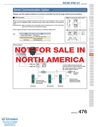
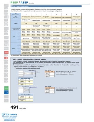
![RCM-PM-01 Controller
Pin No. Signal Name
1 SGA
Pin No. Signal Name
1 SGA
Pin No. Signal Name
1 SGA
Pin No. Signal Name
1 SGA
Pin No. Signal Name
1 SGA
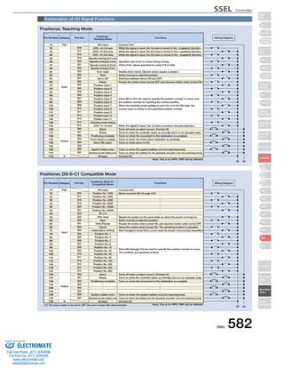
RCM-PM-01 474
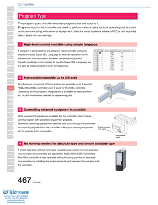
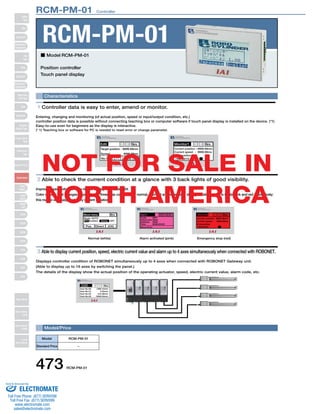
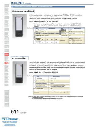
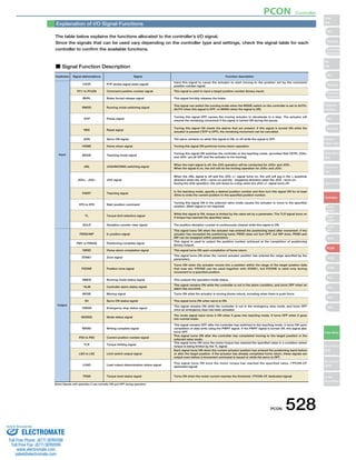
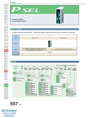
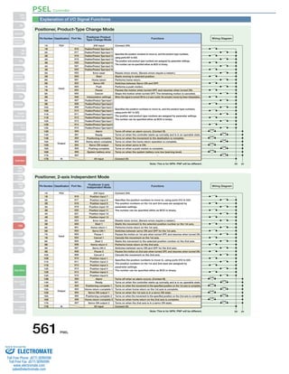
Connecting methods
Pin No. Signal Name
1 DC24V
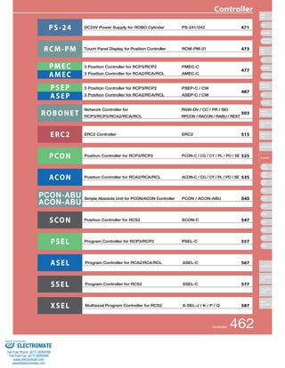
RCM-PM-01
Pin No. Signal Name
1 DC24V
Controller SIO port
[MiniDIN]
24V power
+24V
GND
* The above connection diagram only shows the serial line. Please see the instructions manual
for the controllerfor connecting the power and emergency stop lines.
* The yellowish green wiring is optional.
3m
Controller connection cable
with emergency stop switch
(optional)
Model : CB-PM-SIO030-EB
Standard price:
[When Connecting to a Separate Power Source]
* Please provide the wiring from
the touch panel to the junction.
0.2m
Controller link cable
(option)
Model : CB-RCB-CTL002
Standard price:
* Each controller link cable comes with a e-CON connector,
a junction, and a terminal resistance.
e-CON connector (AMP 4-1473562-4)
Junction (AMP 5-1473574-4)
120Ω1/4W
RCM-PM-01
Emergency stop switch
Controller SIO port
[MiniDIN]
[When Connecting to the Controller's Power Source]
Emergency stop switch
* The yellowish green wiring is optional.
Note:
When linking and using multiple controllers,
you will need a teaching pendant or a PC
software to set the station numbers of
PCON/ACON-CY/SE/PL/PO and ERC2
* The yellowish green wiring is optional.
24V power
+24V
GND
RCM-PM-01
Pin No. Signal Name
1 DC24V
1st controller
SIO port
[MiniDIN]
SGB
5V
ENB
EMGA
24V
GND
EMGB
2nd controller
SIO port
[MiniDIN]
SGB
5V
ENB
EMGA
24V
GND
EMGB
nth controller
SIO port
* Each controller link cable comes with a e-CON connector,
a junction, and a terminal resistance.
Terminal resistance
220Ω1/4W
[MiniDIN]
* The above connection diagram only shows the serial line. Please see the instructions manual
for the controller for connecting the power and emergency stop lines.
[When Connecting to Multiple Controllers]
Controller link cable
(option)
1st controller
e-CON connector (AMP 4-1473562-4)
* Please provide the wiring from
the touch panel to the junction
as well as between junctions.
Model : CB-RCB-CTL002
Standard price:
PCON
ACON
SCON
Power I/O cable (supplied with actuator)
[CB-ERC2-PWBIO]
Length: 1m/3m/5m
ERC2 (SIO type)
Junction (AMP 5-1473574-4)
Terminal resistance
R=220Ω
0.2m 0.2m 0.2m
2nd controller
2
3
4
5
6
7
8
2
3
4
5
6
7
8
2
3
4
5
6
7
8
2
3
4
5
6
7
8
SGB
5V
ENB
EMGA
24V
GND
EMGB
GND
FG
RS422 SD+
RS422 SD-RS422
RD+
RS422 RD-RS422
E
SGB
5V
ENB
EMGA
24V
GND
EMGB
GND
FG
RS422 SD+
RS422 SD-RS422
RD+
RS422 RD-RS422
E
2
3
4
5
6
7
8
2
3
4
5
6
7
8
SGB
5V
ENB
EMGA
24V
GND
EMGB
2
3
4
5
6
7
8
GND
FG
RS422 SD+
RS422 SD-RS422
RD+
RS422 RD-RS422
E
2
3
4
5
6
7
8
NOT FOR SALE IN
NORTH AMERICA
Slider
Type
Mini
Standard
Controllers
Integrated
Rod
Type
Mini
Standard
Controllers
Integrated
Table/Arm
/Flat Type
Mini
Standard
Gripper/
Rotary Type
Linear Servo
Type
Cleanroom
Type
Splash-Proof
Controllers
PMEC
/AMEC
PSEP
/ASEP
ROBO
NET
ERC2
PCON
ACON
SCON
PSEL
ASEL
SSEL
XSEL
Pulse Motor
Servo Motor
(24V)
Servo Motor
(200V)
Linear
Servo Motor
Sold Serviced By:
ELECTROMATE
Toll Free Phone (877) SERVO98
Toll Free Fax (877) SERV099
www.electromate.com
sales@electromate.com](https://image.slidesharecdn.com/iairobocylindercontrollercatalog-141015195025-conversion-gate02/85/Iai-robo-cylinder_controller_catalog-14-320.jpg)
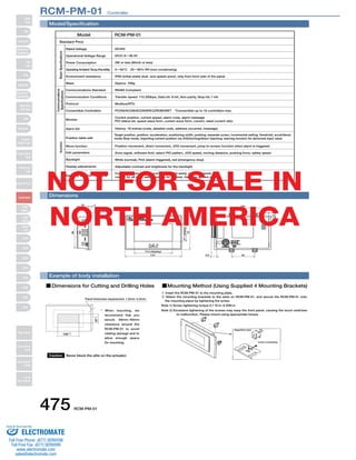
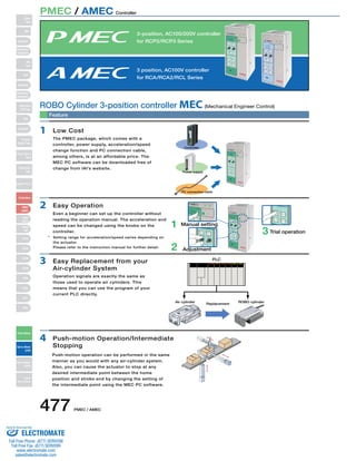
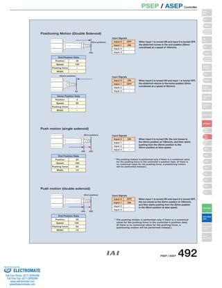
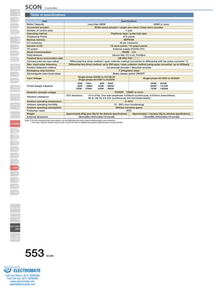
![Specifications Table
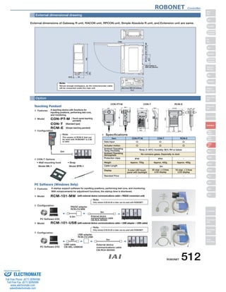
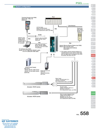
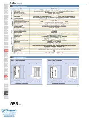
Item Type
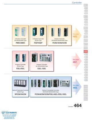
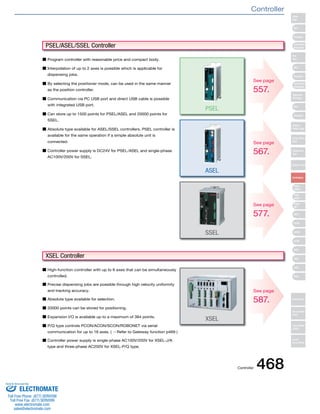
Controller Type PMEC AMEC
Connectible Actuators RCP2/RCP3 Series Actuators RCA/RCA2/RCL Series Actuators
Number of Controllable Axes Single axis
Operation Method Positioner Type
Number of Positions 2 positions / 3 positions
Backup Memory EEPROM
I/O Connector 10-pin terminal block
I/O Points 4 input points / 4 output points
Power for I/O Externally supplied DC24V±10%
Serial Communication RS485: 1ch/USB: 1ch
Position Detection Method Incremental encoder
Note: The minimum/maximum speeds vary depending on the actuator model. For more information, see the instruction manual, or contact IAI.
481 PMEC / AMEC
Power
Green :Normal
Red: Alarm
0.40mA max (AC100V)
0.75mA max (AC200V)
Complete
HOME
SAVE
Test run
Manual
Manual
Continuous
Auto
Ext. Start
Accel Speed Setting
FWD
POS
BACK
POS
Middle
Accel Speed
FWD BACK
RUN STOP
Normal Release
Brake
Teaching Port
Power
Green :Normal
Red: Alarm
Complete
HOME
SAVE
Test run
Manual
Manual
Continuous
Auto
Ext. Start
Accel Speed Setting
FWD
POS
BACK
POS
Middle
Accel Speed
FWD BACK
RUN STOP
Normal Release
Brake
Teaching Port
AC100V-115V±10%
1.3A
30A
AC90V~264V
0.67A (AC100V)/0.36A (AC200V)
15A (AC100V)/30A (AC200V)
0.50mA max
AC100V-115V±10%
2.4A
15A
0.50mA max
500g 508g 614g
Power Supply Voltage
Rated Current
Rush Current
Leak Current
Dielectric Strength Voltage DC500V 1MΩ
Vibration Resistance
XYZ directions 10~57Hz One-side amplitude 0.035mm (continuous), 0.075mm (intermittent)
57~150Hz 4.9m/s2 (continuous), 9.8m/s2 (intermittent)
Ambient Operating Temperature 0~40˚C
Ambient Operating Humidity 10~85% RH (non-condensing)
Ambient Operating Atmosphere Free from corrosive gases
Protection Class IP20
Weight
Outer Dimensions
226
216
85 2-ø5 through
200 42.5
89.8
82
2
85 87.8
80
200
9 182 9
4.1
8.5 68 8.5
4-M3 tapped hole
[With standard mounting bracket]
The standard mounting bracket is supplied with the controller.
Slider
Type
Mini
Standard
Controllers
Integrated
Rod
Type
Mini
Standard
Controllers
Integrated
Table/Arm
/Flat Type
Mini
Standard
Gripper/
Rotary Type
Linear Servo
Type
Cleanroom
Type
Splash-Proof
Controllers
PMEC
/AMEC
PSEP
/ASEP
ROBO
NET
ERC2
PCON
ACON
SCON
PSEL
ASEL
SSEL
XSEL
Pulse Motor
Servo Motor
(24V)
Servo Motor
(200V)
Linear
Servo Motor
PMEC / AMEC Controller
Sold Serviced By:
ELECTROMATE
Toll Free Phone (877) SERVO98
Toll Free Fax (877) SERV099
www.electromate.com
sales@electromate.com](https://image.slidesharecdn.com/iairobocylindercontrollercatalog-141015195025-conversion-gate02/85/Iai-robo-cylinder_controller_catalog-21-320.jpg)
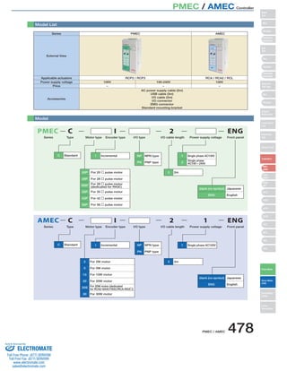
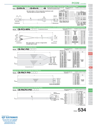
![Components for maintenance
Please refer to the models mentioned below when arrangements such as cable replacement are needed after purchasing the product.
[RCP3/RCP2 (for specific models*) /RCA2/RCL]-[PMEC/AMEC] Motor encoder integrated cable for indirect connection
* For RCP2-GRSS/GRLS/GRST/SRA4R/SRGS4R/SRGD4R
[RCP2]-[PMEC] Integrated motor-encoder connection cable
[RCA]-[AMEC] Integrated motor-encoder connection cable
485 PMEC / AMEC
[PCON](ACON)
White [ - ](A+)
Black (label)[BK+](LS+)
Mechanical side Controller side
Red [ U ]
L
Mechanical side Controller side
Pin number
1
2
3
18
17
7
16
1
2
3
4
10
11
14
13
15
6
5
8
12
9
Yellow [ V ]
NC
NC
Black [ W ]
NC
Orange [ BK+ ]
Gray [ BK- ]
Black [ LS+ ]
Brown [ LS- ]
White [ A+ ]
Yellow [ A- ]
Red [ B+ ]
Green [ B- ]
Black (label)[Z+]
Brown (label)[Z-]
White (label)[VCC]
Yellow (label)[VPS]
Red (label)[GND]
Green (label)[(Spare)]
NC
NC
NC
Shield [ FG ]
Pin number
1
2
3
4
5
6
7
8
9
10
11
12
13
14
15
16
17
18
19
20
21
22
23
24
Model CB-ASEP-MPA□□□
Mechanical side Controller side
L
Black [ ØA ]
Mechanical side Controller side
Pin number
124536
16
17
56
13
14
1234
10
11
9
12
15
78
18
White [ VMM ]
Red [ ØB ]
Green [ VMM ]
Brown [ Ø/A ]
Yellow [ Ø/B ]
Orange [ BK+ ]
Gray [ BK- ]
NC
NC
Black [ LS+ ]
Brown [ LS- ]
White [ A+ ]
Yellow [ A- ]
Red [ B+ ]
Green [ B- ]
White (label)[VCC]
Yellow (label)[VPS]
Red (label)[GND]
Green (label)[(Spare)]
NC
NC
NC
Shield [ FG ]
Pin number
1234569
10
11
12
78
13
14
15
16
17
18
19
20
21
22
23
24
Model CB-PSEP-MPA□□□
Mechanical side Controller side
NC
L
Mechanical side Controller side
Pin number
A1
B1
A2
B2
A3
B3
A4
B4
A6
B6
A7
B7
A8
B8
A5
B5
A9
B9
A10
B10
A11
B11
Pin number
12534678
11
12
13
14
15
16
9
10
20
18
17
19
21
24
22
23
Black [ ØA ](U)
White [VMM](V)
Brown [ Ø/A ](W)
Green [ ØB ]( - )
Yellow [VMM]( - )
Red [ Ø/B ]( - )
Orange [LS+](BK+)
Gray [LS-](BK-)
Yellow [ - ](A-)
Red [ A+ ](B+)
Green [ A- ](B-)
Black [ B+ ](Z+)
Brown [ B- ](Z-)
Brown (label)[BK-](LS-)
Green (label)[GNDLS](GNDLS)
Red (label)[VPS](VPS)
White (label)[VCC](VCC)
Yellow (label)[GND](GND)
Shield [FG](FG)
NC
NC
Model CB-APSEP-MPA□□□
* Enter cable length (L) required in □□□ (compatible for up to max. 20m).
Example: 080=8m
*Enter cable length (L) required in □□□ (compatible for up to max. 20m).
Example: 080=8m
*Enter cable length (L) required in □□□ (compatible for up to max. 20m).
Example: 080=8m
Min. bend radius r=68mm or larger (when movable unit is used)
Min. bend radius r=68mm or larger (when movable unit is used)
Min. bend radius r=68mm or larger (when movable unit is used)
Slider
Type
Mini
Standard
Controllers
Integrated
Rod
Type
Mini
Standard
Controllers
Integrated
Table/Arm
/Flat Type
Mini
Standard
Gripper/
Rotary Type
Linear Servo
Type
Cleanroom
Type
Splash-Proof
Controllers
PMEC
/AMEC
PSEP
/ASEP
ROBO
NET
ERC2
PCON
ACON
SCON
PSEL
ASEL
SSEL
XSEL
Pulse Motor
Servo Motor
(24V)
Servo Motor
(200V)
Linear
Servo Motor
PMEC / AMEC Controller
Sold Serviced By:
ELECTROMATE
Toll Free Phone (877) SERVO98
Toll Free Fax (877) SERV099
www.electromate.com
sales@electromate.com](https://image.slidesharecdn.com/iairobocylindercontrollercatalog-141015195025-conversion-gate02/85/Iai-robo-cylinder_controller_catalog-25-320.jpg)
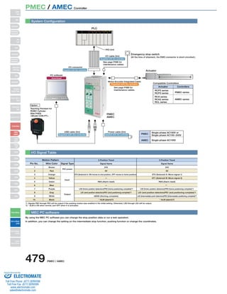
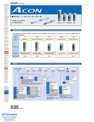
![*The 3 types differ in cable length: 020=2m, 030=3m,
050=5m
4 Yellow
5 Green
6 Blue
7 Purple
8 Grey
9 White Output
10 Black
PMEC / AMEC 486
[RCP2 small rotary]-[PMEC] Motor encoder integrated cable for indirect connection
L
Mechanical side Controller side
Black [ ØA ]
Mechanical side Controller side
Pin number
A1
B1
A2
B2
A3
B3
A6
B6
A7
B7
A8
B8
A4
B4
A5
B5
A9
B9
A10
B10
A11
B11
White [ VMM ]
Brown [ Ø/A ]
Green [ ØB ]
Yellow [ VMM ]
Red [ Ø/B ]
Orange [ LS+ ]
Gray [ LS- ]
Red [ A+ ]
Green [ A- ]
Black [ B+ ]
Brown [ B- ]
NC
NC
Black (label)[BK+]
Brown (label)[BK-]
Green (label)[GNDLS]
Red (label)[VPS]
White (label)[VCC]
Yellow (label)[GND]
NC
Shield [ FG ](FG)
NC
NC
Pin number
1
2
5
3
4
6
7
8
13
14
15
16
7
8
9
10
20
18
17
19
21
24
22
23
Model CB-RPSEP-MPA□□□
Model CB-APMEC-PIO□□□-NC
L
Flat cable (10 pin)
I/O cable for PMEC-C/AMEC-C
*Enter cable length (L) required in □□□ (compatible for up to max. 20m).
Example: 080=8m
Min. bend radius r=68mm or larger (when movable unit is used)
Pin NO. Electric
wire color Signal
1 Brown
PIO
Power
2 Red supply
3 Orange
Input
Slider
Type
Mini
Standard
Controllers
Integrated
Rod
Type
Mini
Standard
Controllers
Integrated
Table/Arm
/Flat Type
Mini
Standard
Gripper/
Rotary Type
Linear Servo
Type
Cleanroom
Type
Splash-Proof
Controllers
PMEC
/AMEC
PSEP
/ASEP
ROBO
NET
ERC2
PCON
ACON
SCON
PSEL
ASEL
SSEL
XSEL
Pulse Motor
Servo Motor
(24V)
Servo Motor
(200V)
Linear
Servo Motor
PMEC / AMEC Controller
Sold Serviced By:
ELECTROMATE
Toll Free Phone (877) SERVO98
Toll Free Fax (877) SERV099
www.electromate.com
sales@electromate.com](https://image.slidesharecdn.com/iairobocylindercontrollercatalog-141015195025-conversion-gate02/85/Iai-robo-cylinder_controller_catalog-26-320.jpg)
![PSEP / ASEP Controller
PLC
Field network
DeviceNet/CC-Link/ProfiBus
Teaching Pendant for
CON/RCON/SEP
See P497
Model: CON-PT/CON-PD/CON-PG
Teaching Pendant for SEP
Model: SEP-PT
5m
PC Software
See P499
RS232 version:
Model: RCM-101-MW
USB version:
Model: RCM-101-USB
* Cable supplied with the PC
software.
* Version older than 7.00.01.00
cannot be used with the SEP
controller.
Standard 0.5m
Absolute Battery Unit for SEP Controller
(Supplied with simple absolute type)
Model: SEP-ABU (standard)
Model: SEP-ABU-W (for dustproof)
See P500
PIO Cable
Model: CB-APSEP-PIO020 (standard)
Model: CB-APSEPW-PIO020 (for dustproof)
Standard 2m
(Supplied with the controller)
See P502
DC24V Power Supply
Model: PS-241 (100V input)
Model: PS-242 (200V input)
PCON/RPCON/PSEL
Motor-encoder Integrated Cable
Model: CB-PCS-MPA
Standard 1m / 3m / 5m
(Supplied with the actuator)
See P501
Rotary typeޓRCP2-RT
(See below for small rotary)
Gripper typeޓRCP2-GRS/GRM/GR3
Motor-encoder Integrated Cable
Model: CB-RPSEP-MPA
Standard 1m / 3m / 5m
(Supplied with the actuator)
See P502
Motor-encoder Integrated Cable
Model: CB-APSEP-MPA
Standard 1m / 3m / 5m
(Supplied with the actuator)
See P501
Actuator: RCP2 series
RCP2 Small Rotary
(RCP2-RTBS/RTBSL/
RTCS/RTCSL)
Motor-encoder Integrated Cable
Model: CB-PSEP-MPA
Standard 1m / 3m / 5m
(Supplied with the actuator)
See P501
Actuator: RCP3 series
* The above models use a
dedicated cable.
RCP2-GRSS/GRLS/GRST
RCP2-SRA4R/SRGS4R/SRGD4R
System structure
[PSEP]
Slider
Type
Mini
Standard
Controllers
Integrated
Rod
Type
Mini
Standard
Controllers
Integrated
Table/Arm
/Flat Type
Mini
Standard
Gripper/
Rotary Type
Linear Servo
Type
Cleanroom
Type
Splash-Proof
Controllers
PMEC
/AMEC
PSEP
/ASEP
ROBO
NET
ERC2
PCON
ACON
SCON
PSEL
ASEL
SSEL
XSEL
Pulse Motor
Servo Motor
(24V)
Servo Motor
(200V)
Linear
Servo Motor
489 PSEP / ASEP
Sold Serviced By:
ELECTROMATE
Toll Free Phone (877) SERVO98
Toll Free Fax (877) SERV099
www.electromate.com
sales@electromate.com](https://image.slidesharecdn.com/iairobocylindercontrollercatalog-141015195025-conversion-gate02/85/Iai-robo-cylinder_controller_catalog-29-320.jpg)
![PSEP / ASEP Controller
PLC
Field network
DeviceNet/CC-Link/ProfiBus
System structure
[ASEP]
PC Software
See P499
RS232 version:
Model: RCM-101-MW
USB version:
Model: RCM-101-USB
Teaching Pendant for
CON/RCON/SEP
See P497
Model: CON-PT/CON-PD/CON-PG
Teaching Pendant for SEP
Model: SEP-PT
5m
Standard 0.5m
Absolute Battery Unit for SEP Controller
(Supplied with simple absolute type)
Model: SEP-ABU (standard)
Model: SEP-ABU-W (for dustproof)
See P500
PIO Cable
Model: CB-APSEP-PIO020 (standard)
Model: CB-APSEPW-PIO020 (for dustproof)
Standard 2m
(Supplied with the controller)
See P502
DC24V Power Supply
Model: PS-241 (100V input)
Model: PS-242 (200V input)
Motor-encoder Integrated Cable
Model: CB-ACS-MPA
Standard 1m / 3m / 5m
(Supplied with the actuator)
See P502
Motor-encoder Integrated Cable
Model: CB-ASEP-MPA
Standard 1m / 3m / 5m
(Supplied with the actuator)
See P501
Motor-encoder Integrated Cable
Model: CB-APSEP-MPA
Standard 1m / 3m / 5m
(Supplied with the actuator)
See P501
Actuator: RCA series
ACON/RACON/ASEL
Actuator: RCA2/RCL series
* Cable supplied with the PC
software.
* Version older than 7.00.01.00
cannot be used with the SEP
controller.
Slider
Type
Mini
Standard
Controllers
Integrated
Rod
Type
Mini
Standard
Controllers
Integrated
Table/Arm
/Flat Type
Mini
Standard
Gripper/
Rotary Type
Linear Servo
Type
Cleanroom
Type
Splash-Proof
Controllers
PMEC
/AMEC
PSEP
/ASEP
ROBO
NET
ERC2
PCON
ACON
SCON
PSEL
ASEL
SSEL
XSEL
Pulse Motor
Servo Motor
(24V)
Servo Motor
(200V)
Linear
Servo Motor
PSEP / ASEP 490
Sold Serviced By:
ELECTROMATE
Toll Free Phone (877) SERVO98
Toll Free Fax (877) SERV099
www.electromate.com
sales@electromate.com](https://image.slidesharecdn.com/iairobocylindercontrollercatalog-141015195025-conversion-gate02/85/Iai-robo-cylinder_controller_catalog-30-320.jpg)
![PSEP / ASEP Controller
Spare parts
When you need spare parts after purchasing the product, such as when replacing a cable, refer to the list of models below.
Motor-encoder integrated cable for connecting [RCP3/RCA2/RCL] and [PSEP/ASEP]
Model CB-APSEP-MPA□□□
* Enter the cable length (L) into □□□ . Compatible to a maximum of 20 meters.
Ex. 080 = 8m
Motor-encoder integrated cable for connecting [RCP2] and [PSEP]
Model CB-PSEP-MPA□□□
Motor-encoder integrated type cable for RCP3/RCP2 (Limited to RCP2-GRSS/GRLS/GRST/SRA4R/SRGS4R/SRGD4R types)
(Front view) (Front view)
Min. bend radius r = 84 mm or larger (when movable type is used)
Motor-encoder integrated cable for connecting [RCA] and [ASEP]
Mechanical side Controller side
501 PSEP / ASEP
Signal Pin Number
Mechanical side Controller side
Red [ U ]
L
Pin number
12
3
18
17
7
16
1234
10
11
14
13
15
658
12
9
Yellow [ V ]
NC
NC
Black [ W ]
NC
Orange [ BK+ ]
Gray [ BK- ]
Black [ LS+ ]
Brown [ LS- ]
White [ A+ ]
Yellow [ A- ]
Red [ B+ ]
Green [ B- ]
Black ( label) [Z+]
Brown ( label) [Z-]
White ( label) [VCC]
Yellow ( label) [VPS]
Red ( label) [GND]
Green ( label) [(spare)]
NC
NC
NC
Shield [ FG ]
Pin number
123456789
10
11
12
13
14
15
16
17
18
19
20
21
22
23
24
Model CB-ASEP-MPA□□□
Mechanical side Controller side
L
Black [ ǞA ]
Pin number
1
2
4
5
3
6
16
17
5
6
13
14
1
2
3
4
10
11
9
12
15
7
8
18
White [ VMM ]
Red [ ǞB ]
Green [ VMM ]
Brown [ Ǟ/A ]
Yellow [ Ǟ/B ]
Orange [ BK+ ]
Gray [ BK- ]
NC
NC
Black [ LS+ ]
Brown [ LS- ]
White [ A+ ]
Yellow [ A- ]
Red [ B+ ]
Green [ B- ]
White ( label) [VCC]
Yellow ( label) [VPS]
Red ( label) [GND]
Green ( label) [(spare)]
NC
NC
NC
Shield [ FG ]
Pin number
1
2
3
4
5
6
9
10
11
12
7
8
13
14
15
16
17
18
19
20
21
22
23
24
Mechanical side Controller side
Mechanical side Controller side
[PCON] (ACON)
L
Pin number
A1
B1
A2
B2
A3
B3
A4
B4
A6
B6
A7
B7
A8
B8
A5
B5
A9
B9
A10
B10
A11
B11
Black [ ǞA ](U)
White [VMM](V)
Brown [ Ǟ/A ](W)
Green [ ǞB ]( - )
Yellow [VMM]( - )
Red [ Ǟ/B ]( - )
Orange [LS+](BK+)
Gray [LS-](BK-)
White [ - ](A+)
Yellow [ - ](A-)
Red [ A+ ](B+)
Green [ A- ](B-)
Black [ B+ ](Z+)
Brown [ B- ](Z-)
Black ( label) [BK+](LS+)
Brown ( label) [BK-](LS-)
Green ( label) [GNDLS](GNDLS)
Red ( label) [VPS](VPS)
White ( label) [VCC](VCC)
Yellow ( label) [GND](GND)
NC
Shield [FG](FG)
NC
NC
Pin number
1
2
5
3
4
6
7
8
11
12
13
14
15
16
9
10
20
18
17
19
21
24
22
23
Mechanical side Controller side
* Enter the cable length (L) into □□□ . Compatible to a maximum of 20 meters.
Ex. 080 = 8m
L
(15)
(ø12)
A1 A Black
(18)
(8)
(20)
(8)
(5)
(30)
(18)
(23)
Pin Number Signal (Wire color)
A B1
BK+ 14
Mechanical side Controller side
B1
A2
B2
A3
B3
A4
B4
A5
B5
A6
B6
A7
B7
A8
B8
A9
B9
A10
B10
A11
B11
VMM
/A
B
VMM
/B
NC
NC
BK+
BK−
LS+
LS−
A+
A−
B+
B−
NC
VPS
VCC
GND
NC
FG
White
Red
Green
Yellow
Brown
Pink (Red )
Pink (Blue )
White (Red )
White (Blue )
Orange (Red )
Orange (Blue )
Gray (Red )
Gray (Blue )
Orange (Blue Consecutive)
Gray (Red Consecutive)
Gray (Blue Consecutive)
Shield
VMM
/A
B
VMM
/B
A2
A1
B3
B2
A3
13
16
15
12
11
10
9
8
7
6
5
4
1
BK−
LS+
LS−
A+
A−
B+
B−
NC
VPS
VCC
GND
NC
FG
Model CB-PCS-MPA□□□
* Enter the cable length (L) into □□□ . Compatible to a maximum of 20 meters.
Ex. 080 = 8m
* Enter the cable length (L) into □□□ . Compatible to a maximum of 20 meters.
Ex. 080 = 8m
Min. bend radius r = 68 mm or larger (when movable type is used)
Min. bend radius r = 68 mm or larger (when movable type is used)
Min. bend radius r = 68 mm or larger (when movable type is used)
Slider
Type
Mini
Standard
Controllers
Integrated
Rod
Type
Mini
Standard
Controllers
Integrated
Table/Arm
/Flat Type
Mini
Standard
Gripper/
Rotary Type
Linear Servo
Type
Cleanroom
Type
Splash-Proof
Controllers
PMEC
/AMEC
PSEP
/ASEP
ROBO
NET
ERC2
PCON
ACON
SCON
PSEL
ASEL
SSEL
XSEL
Pulse Motor
Servo Motor
(24V)
Servo Motor
(200V)
Linear
Servo Motor
Sold Serviced By:
ELECTROMATE
Toll Free Phone (877) SERVO98
Toll Free Fax (877) SERV099
www.electromate.com
sales@electromate.com](https://image.slidesharecdn.com/iairobocylindercontrollercatalog-141015195025-conversion-gate02/85/Iai-robo-cylinder_controller_catalog-41-320.jpg)
![PSEP / ASEP Controller
(Wire color)
Motor-encoder integrated cable for connecting [RCA2/RCL] and [ACON/RACON/ASEL]
Pin Number Signal Signal Pin Number
10 9
10 9
51353-1000 (MOLEX)
2
3
4
5
6
7 OUT0
OUT1
OUT2
8
9
Brown
51353-1000 (MOLEX)
2
3
4
5
6
7 OUT0
OUT1
OUT2
8
9
Brown
2
3
PSEP / ASEP 502
(Front view) (Front view)
Min. bend radius r = 84 mm or larger (when movable type is used)
Motor-encoder integrated cable for connecting [RCP2 mini rotary] and [PSEP]
L
Mechanical side Controller side
Black [ ØA ]
Mechanical side Controller side
Pin number
A1
B1
A2
B2
A3
B3
A6
B6
A7
B7
A8
B8
A4
B4
A5
B5
A9
B9
A10
B10
A11
B11
White [ VMM ]
Brown [ Ø/A ]
Green [ ØB ]
Yellow [ VMM ]
Red [ Ø/B ]
Orange [ LS+ ]
Gray [ LS- ]
Red [ A+ ]
Green [ A- ]
Black [ B+ ]
Brown [ B- ]
NC
NC
Black ( label) [BK+]
Brown ( label) [BK-]
Green ( label) [GNDLS]
Red ( label) [VPS]
White ( label) [VCC]
Yellow ( label) [GND]
NC
Shield [ FG ] (FG)
NC
NC
Pin number
1
2
5
3
4
6
7
8
13
14
15
16
7
8
9
10
20
18
17
19
21
24
22
23
Model CB-RPSEP-MPA□□□
2
1
OUT3
10
Signal Color Wire
24V
Brown-
White
Red
Red-
White
Cable
No.
1
Yellow
Yellow-
White
Green
Green-
White
Black
Black-
White
(crimped)
0V
IN0
IN1
IN2
IN3
I/O cable for PSEP-C/ASEP-C
Model CB-APSEPW-PIO□□□
L
I/O cable for PSEP-CW/ASEP-CW
2
1
OUT3
10
Signal Color Wire
24V
Red
Orange
Yellow
No.
1
Green
Blue
Purple
Gray
White
Black
(crimped)
0V
IN0
IN1
IN2
IN3
L
Flat
cable
Model CB-APSEP-PIO□□□
* Enter the cable length (L) into □□□ . Compatible to a maximum of 20 meters.
Ex. 080 = 8m
* Enter the cable length (L) into □□□ . Compatible to a maximum of 10 meters.
Ex. 080 = 8m
* Enter the cable length (L) into □□□ . Compatible to a maximum of 10 meters.
Ex. 080 = 8m
L
Red U
A1 U 1
BK+ 16
(10)
(ø12)
(18)
(8)
(12)
(23)
(8)
(5)
(30)
(18)
Mechanical side Controller side
B1
A2
B2
A3
B3
A4
B4
A5
B5
A6
B6
A7
B7
A8
B8
A9
B9
A10
B10
A11
B11
V
W
NC
NC
NC
BK+
BK−
LS+
LS−
A+
A−
B+
B−
Z+
Z−
−
/PS
VCC
GND
NC
FG
Yellow
Black
Yellow (Red )
Yellow (Blue )
Pink (Red )
Pink (Blue )
White (Red )
White (Blue )
Orange (Red )
Orange (Blue )
Gray (Red )
Gray (Blue )
Orange (Red Consecutive)
Orange (Blue Consecutive)
Gray (Red Consecutive)
Gray (Blue Consecutive)
Shield
BK−
LS+
LS−
A+
A−
B+
B−
Z+
Z−
−
/PS
VCC
GND
NC
FG
15
18
17
14
13
12
11
10
9
8
7
6
5
1
V
W
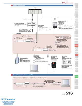
Model CB-ACS-MPA□□□
* Enter the cable length (L) into □□□ . Compatible to a maximum of 20 meters.
Ex. 080 = 8m
Min. bend radius r = 68 mm or larger (when movable type is used)
Slider
Type
Mini
Standard
Controllers
Integrated
Rod
Type
Mini
Standard
Controllers
Integrated
Table/Arm
/Flat Type
Mini
Standard
Gripper/
Rotary Type
Linear Servo
Type
Cleanroom
Type
Splash-Proof
Controllers
PMEC
/AMEC
PSEP
/ASEP
ROBO
NET
ERC2
PCON
ACON
SCON
PSEL
ASEL
SSEL
XSEL
Pulse Motor
Servo Motor
(24V)
Servo Motor
(200V)
Linear
Servo Motor
Sold Serviced By:
ELECTROMATE
Toll Free Phone (877) SERVO98
Toll Free Fax (877) SERV099
www.electromate.com
sales@electromate.com](https://image.slidesharecdn.com/iairobocylindercontrollercatalog-141015195025-conversion-gate02/85/Iai-robo-cylinder_controller_catalog-42-320.jpg)
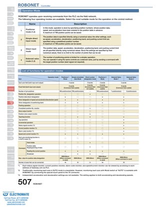
![The robot can be moved by directly specifying numeric values
for the move position/velocity/acceleration and other data.
4 Can operate with a maximum of 16 axes. Communication
unit
ROBONET
controller
Up to 16 units can be connected
Controllers can be multiplexed. 5
FG
FG
Simple absolute unit, when home return is not required 6
The simple absolute R unit allows operation for
incremental specification axes without home return. Users
can back up actuator encoder data even if the power is
shut off, by installing a simple absolute R unit to a RACON
unit (controller for RCA) or RPCON unit (controller for
RCP2).
2
3 Ultra-compact
RACON
RPCON
Standard controller
(ACON/PCON)
Simple absolute R unit
Mounting the DIN rail
The controller is installed with DIN rails, so it can be fastened and removed with one touch. 7
PLC
Field Network
Extension unit
[REXT]
Extension unit
[REXT]
Unit link
cable (1m)
[CB-REXT-SIO010]
Movement by specifying positions
Movement by specifying direct values
Specifying speed/acceleration
Current value output
○
○
○
○
○
△
(Not for PIO)
(Connectable with
serial communication)
*ROBONET operates through a field network,
and the standard controller operates with PIO.
Besides the conventional method of moving the robot to
pre-taught positions it is also possible to operate the
robot by sending information as a string of numeric data
that contains position, velocity, acceleration, etc. values.
This is effective for cases such as when the move position
changes with each piece or when one wants to move the
robot to an arbitrary position.
Each unit is an ultra-compact size of 34mm wide by
100mm high x 73mm deep. Also, since there is no base
unit and the main unit is coupled with connectors, the
controller takes up little space for installation even if there
are many units.
Up to 16 controllers can be connected to one
communication unit (Gateway R unit).
RACON units (controllers for RCA) and RPCON
units (controllers for RCP2) can also be used
together.
Controllers can be multiplexed using an optional extension
unit, so many axes can be connected even if there isn’t
much horizontal space.
Also, non-ROBONET controllers (SCON, PCON-CF, ERC2)
can be connected to a ROBONET Gateway unit using the
same extension unit.
ROBONET Controller
ROBONET 504
Slider
Type
Mini
Standard
Controllers
Integrated
Rod
Type
Mini
Standard
Controllers
Integrated
Table/Arm
/Flat Type
Mini
Standard
Gripper/
Rotary Type
Linear Servo
Type
Cleanroom
Type
Splash-Proof
Controllers
PMEC
/AMEC
PSEP
/ASEP
ROBO
NET
ERC2
PCON
ACON
SCON
PSEL
ASEL
SSEL
XSEL
Pulse Motor
Servo Motor
(24V)
Servo Motor
(200V)
Linear
Servo Motor
Sold Serviced By:
ELECTROMATE
Toll Free Phone (877) SERVO98
Toll Free Fax (877) SERV099
www.electromate.com
sales@electromate.com](https://image.slidesharecdn.com/iairobocylindercontrollercatalog-141015195025-conversion-gate02/85/Iai-robo-cylinder_controller_catalog-44-320.jpg)
![System configuration
PC Software (optional)
RS232 version
Model: RCM-101-MW
DC24V Power Supply
ROBONET Extension Unit
PLC
Teaching Box
(Optional)
Model: CON-PT/CON-T/RCM-E/RCM-P
(See P512)
USB version
Model: RCM-101-USB
(See P512)
Model: PS-241 (100V input)
Model: PS-242 (200V input)
(See P471)
Actuator: RCP3 series
Motor-encoder Integrated Cable (supplied with the actuator)
Model: CB-PCS-MPA
(See P513)
• DeviceNet
Motor-encoder Integrated Cable (supplied with the actuator)
Model: CB-ACS-MPA
(See P514)
Encoder Cable (supplied with the actuator)
Model: CB-RCP2-PB
(See P513)
Motor Cable (supplied with the actuator)
Model: CB-RCP2-MA (see P513)
Encoder Cable (supplied with the actuator)
Model: CB-ACS-PA (see P514)
Field Network
Motor Cable (supplied with the actuator)
Model: CB-ACS-MA (see P514)
Actuator: RCP2 series
Actuator: RCA series
Gateway Parameter-
Setting Tool (included)
Actuator: RCA2 series
• CC-Link
• ProfiBus
* When using the actuator with the simple absolute
specification, install the simple absolute R unit, then
connect the encoder cable to the simple absolute R unit.
If multiple ROBONET extension units (optional) are linked together they can reduce the lateral width
needed. It is also possible to connect individual controllers, such as SCON, etc. via the ROBONET.
[Unit Multiplex Set]
Model: REXT-SIO
(Set Contents)
ROBONET Extension Unit (Model: REXT) 2 pc
Unit Link Cable 1 pc
(Model: CB-REXT-SIO010)
FG
FG
PLC
Field Network
Extension unit
[REXT]
Extension unit
[REXT]
Unit Link
cable (1m)
[CB-REXT-SIO010]
[Controller Connecting Set]
Model: REXT-CTL
(Set Contents)
ROBONET Extension Unit (Model: REXT) 1 pc
Controller Connection Cable 1 pc
(Model: CB-REXT-CTL010)
R
EMG±
e-CON
e-CON
EMG±
FG
PLC
Field Network
Extension unit
[REXT]
Controller
link cable (0.2m)
[CB-RCB-CTL002]
Controller
connection cable (1m)
(Included)
[CB-REXT-CTL010]
EMG±
ROBONET Controller
505 ROBONET
Slider
Type
Mini
Standard
Controllers
Integrated
Rod
Type
Mini
Standard
Controllers
Integrated
Table/Arm
/Flat Type
Mini
Standard
Gripper/
Rotary Type
Linear Servo
Type
Cleanroom
Type
Splash-Proof
Controllers
PMEC
/AMEC
PSEP
/ASEP
ROBO
NET
ERC2
PCON
ACON
SCON
PSEL
ASEL
SSEL
XSEL
Pulse Motor
Servo Motor
(24V)
Servo Motor
(200V)
Linear
Servo Motor
Sold Serviced By:
ELECTROMATE
Toll Free Phone (877) SERVO98
Toll Free Fax (877) SERV099
www.electromate.com
sales@electromate.com](https://image.slidesharecdn.com/iairobocylindercontrollercatalog-141015195025-conversion-gate02/85/Iai-robo-cylinder_controller_catalog-45-320.jpg)
![ROBONET Controller
Option
No. of connectible units for each unit of PS-24
Controller type Actuator type Simultaneous
RPCON 8
PCON
SA4, SA5 (20W)
SA6 (30W)
RA3 (20W)
RA4 (20W)
RA4 (30W)
Maximum
Rated
Maximum
Rated
Maximum
Rated
Maximum
Rated
Maximum
4.4
1.3
4
1.7
5.1
1.3
4.4
1.3
4
PS-241
(100V input model)
PS-242
(200V input model)
Actuator vs. Power Supply Current
Rated
RCP2, all models (= Maximum) 2
(note)
6
Rated 1.3
8
3
RACON
ACON
servo ON for all axes*
No simultaneous
servo ON for all axes*
Power Supply
Current [A]
* Refers to the first servo ON after power-up.
(Note) Excluding HS8C, HS8R, and RA10C
* For PSEL/ASEL, this is different depending on the number of axes and model.
Please inquire for details.
DC24V Power Supply
Features
A 24V power supply for ROBO Cylinder
that can output 17A of momentary
current. Power supply units can be
operated in parallel, and up to 5 units
can be added if a unit runs out of
capacity.
Model
4
3
3
4
6
5
6
6
Spare parts
When spare parts are necessary after purchasing the product, such as when replacing a cable, refer to a list of the models below.
ROBONET
connection board
(simple absolute
connection board)
Model JB-1
Terminal resistor
board
Model TN-1
Power
connection
board
Model PP-1
A A
I-1318119-3
(AMP)
Motor cable for RCP2
Min. bend radius r = 50 mm or larger (when movable type is used)
Encoder Cable/Encoder Robot Cable for RCP2
(5) (8) (13) (15)
Min. bend radius r = 50 mm or larger (when movable type is used)
* Only the robot cable is to be used in a cable track.
Motor-encoder integrated type cable for RCP3/RCP2 (Limited to RCP2-GRSS/GRLS/GRST/SRA4R/SRGS4R/SRGD4R types)
L
(15)
(ø12)
A B1 Black A1 A
BK+ 14
(18)
(8)
(20)
(Front view) (Front view)
(8)
(5)
(30)
(18)
(23)
Signal Pin Number (Wire color) Pin Number Signal
Controller side Mechanical side
VMM
/A
B
VMM
/B
A2
A1
B3
B2
A3
13
16
15
12
11
10
9876541
BK−
LS+
LS−
A+
A−
B+
B−
NC
VPS
VCC
GND
NC
FG
White
Red
Green
Yellow
Brown
Pink (Red )
Pink (Blue )
White (Red )
White (Blue )
Orange (Red )
Orange (Blue )
Gray (Red )
Gray (Blue )
Orange (Blue Consecutive)
Gray (Red Consecutive)
Gray (Blue Consecutive)
Shield
B1
A2
B2
A3
B3
A4
B4
A5
B5
A6
B6
A7
B7
A8
B8
A9
B9
A10
B10
A11
B11
VMM
/A
B
VMM
/B
NC
NC
BK+
BK−
LS+
LS−
A+
A−
B+
B−
NC
VPS
VCC
GND
NC
FG
Model CB-PCS-MPA □□□
* Enter the cable length (L) into □□□ . Compatible to a maximum of 20 meters.
Ex.: 080 = 8 m
SLP-06V
(JST)
M cable
CN3 CN1
Orange A1 1 Yellow
(8) (20)
(Front view)
(15)
L
CN3
CN1
(ø8)
(28)
(14)
(14)
(20)
(Front view)
Controller side Mechanical side
Gray
White
Yellow
Pink
Yellow (Green)
VMM
B
A
VMM
B
A2
A3
B1
B2
B3
2
3
4
5
6
VMM
A
B
VMM
B
Gray
Orange
Yellow (Green)
Pink
White
Model CB-RCP2-MA □□□
* The standard cable for the motor cable is the robot cable. Selection is available.
* Enter the cable length (L) into □□□ . Compatible to maximum of 20 meters. Ex.: 080 = 8m
PHDR-16VS
(JST)
XMP-18V
(JST)
Blue (Red 1)
C N 4
C N 2
Cable color
Signal
No.
Pin
No.
Brown Light Gray
(Black 1)
Orange
(Black 2)
1
L S +
L S −
B K +
B K −
E N A
E N A
E N B
E N B
V P S
V B B
(N.C)
(N.C)
(N.C)
F.G
E N A
E N A
E N B
E N B
GND
GND V B B
V P S
L S +
L S −
B K +
B K −
F .G
16
Shield wire
Ground wire
Cable colors
Robot Cable
Robot Cable
Signal
No.
Pin
No.
L
CN2
CN4
(18)
(Front view)
(ø9)
(35)
(25)
(Front view)
Controller side Mechanical side
White
Red
Gray
Brown
Green
Purple
Pink
Yellow
Orange
Blue
Ground
Orange
(Red 2)
Orange
(Black 1)
Orange
(Red 1)
Light Gray
(Black 1)
Light Gray
(Red 1)
White
(Black 1)
White (Red 1)
Yellow
(Black 1)
Pink (Red 1)
Pink (Black 1)
Ground
15
14
13
12
11
10
9
8
7
6
5
4
3
2
1
2
3
4
5
6
7
8
9
10
11
12
13
14
15
16
17
18
Green
Purple
Pink
Blue
Orange
Yellow
Blue (Red 1)
White
Red
Gray
Ground
Light Gray
(Red 1)
White
(Black 1)
White
(Red 1)
Pink (Black 1)
Pink (Red 1)
Yellow
(Black 1)
Orange
(Black 2)
Orange
(Red 2)
Orange
(Black 1)
Orange
(Red 1)
Ground
Standard
Cable
Standard
Cable
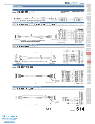
Model CB-RCP2-PB□□□/CB-RCP2-PB□□□-RB
*The standard encoder cable is the normal cable. The robot cable is selectable as an option.
* Enter the cable length (L) into □□□ . Compatible to maximum of 20 meters. Ex.: 080 = 8m
Min. bend radius r = 84 mm or larger (when
movable type is used)
513 ROBONET
Slider
Type
Mini
Standard
Controllers
Integrated
Rod
Type
Mini
Standard
Controllers
Integrated
Table/Arm
/Flat Type
Mini
Standard
Gripper/
Rotary Type
Linear Servo
Type
Cleanroom
Type
Splash-Proof
Controllers
PMEC
/AMEC
PSEP
/ASEP
ROBO
NET
ERC2
PCON
ACON
SCON
PSEL
ASEL
SSEL
XSEL
Pulse Motor
Servo Motor
(24V)
Servo Motor
(200V)
Linear
Servo Motor
Sold Serviced By:
ELECTROMATE
Toll Free Phone (877) SERVO98
Toll Free Fax (877) SERV099
www.electromate.com
sales@electromate.com](https://image.slidesharecdn.com/iairobocylindercontrollercatalog-141015195025-conversion-gate02/85/Iai-robo-cylinder_controller_catalog-53-320.jpg)
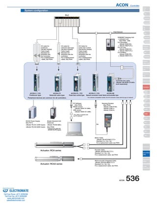
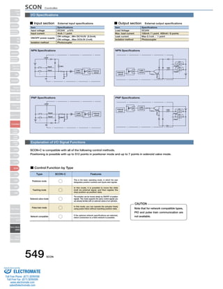
![ACON Controller
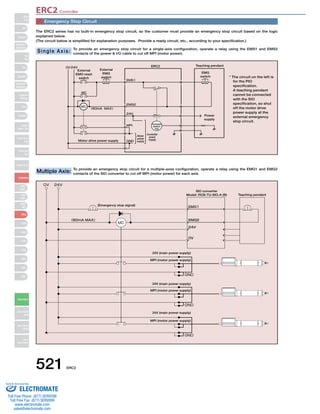
Command Pulse Input State
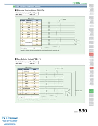
Command pulse train state Input terminal During forward operation During reversed operation
Table of specifications
Motor
Power
Supply
Capacity
(Note 2)
Low High
High Low
Forward pulse train
Reversed pulse train
The forward pulse train causes the motor to rotate forward, and the reverse pulse train causes the motor to rotate in reverse.
Pulse train
Symbols
The command pulse is used for the amount of motor rotation, and the command symbol is used for rotational direction.
A/B phase pulse train
An A/B phase pulse with a 90° phase difference (multiplier is 4) is used to generate commands for the amount of rotation and rotational direction.
Forward pulse train
Reversed pulse train
Pulse train
Symbols
A/B phase pulse train
PP・/PP
NP・/NP
PP・/PP
NP・/NP
PP・/PP
NP・/NP
PP・/PP
NP・/NP
PP・/PP
NP・/NP
PP・/PP
NP・/NP
Positive logic Negative logic
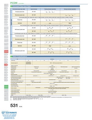
Item Specifications
Positioner type Solenoid valve type
— 64 points
4 input points / 6 output points 4 input points/4 output points None
CB-PACPU-PIO □□□
Differential line driver Open collector —
— Max. 200 kpps Max. 60 kpps —
External
ON/OFF terminal signal inside the power terminal for brake release
XYZ directions 10 to 57Hz, One side amplitude: 0.035mm (continuous), 0.075mm (intermittent)
58 to 150 Hz 4.9 m/s2 (continuous), 9.8 m/s2 (intermittent)
Standard specifications/high acceleration and deceleration model
Rated [A] Max. [A]
Power-saving model
—
Rated [A] Max. [A]
RCA Series Actuator
1-axis
EEPROM
40-pin connector 12-pin connector 14-pin connector None
16 input points/16 output points
External supply DC24V±10%
RS485 1ch
CB-PAC-PIO □□□ CB-PACY-PIO □□□ CB-RCB-CTL002
Controller type
Actuator
RCA
RCA2
RCL
Motor
1.3
1.3
1.3
1.7
0.8
1.0
1.3
1.3
1.3
1.3
1.7
2.5
2.5
2.2
3.4
10W
20W [Model symbol: 20]
30W
20W [Model symbol: 20S]
SA4, RA3, TA5
Type dedicated
2W
5W
10W
4.4
4.4
4.4
5.1
4.6
6.4
6.4
Connected actuator
Number of control axes
Operating method
Positioning Points
Backup memory
I/O connector
Number of I/O
I/O power
Serial Communication
Peripheral device communication cable
Command pulse train input method
Max. input pulse frequency (Note 1)
Position detection method
Drive-source cutoff relay at emergency stop
Forced release of electromagnetic brake
Input Voltage
Dielectric strength voltage
Vibration resistance
Ambient operating temperature
Ambient operating humidity
Ambient operating atmosphere
Protection class
Weight
C CG CY PL PO SE
Pulse train input type Serial communication type
512 points 3 points
—
Incremental encoder
Integrated
Brake release switch ON/OFF
DC24V ± 10%
DC500V 1MΩ
0 ~ 40°C
10 - 95% (non-condensing)
Without corrosive gases
IP20
Approx. 300g Approx. 130g
(Note 1) With the open collector specification, keep the maximum input frequency to 60 kpps or below to prevent malfunction. For applications exceeding 60kpps, use the differential line driver.
(Note 2) Other than motor power supply capacity, increase 0.5A as control power supply. Inrush current of approx. 5 to 12 times the rated current occurs within 1 to 2 msec from
turning the power on. The inrush current changes depending on the power supply line impedance.
541 ACON
Slider
Type
Mini
Standard
Controllers
Integrated
Rod
Type
Mini
Standard
Controllers
Integrated
Table/Arm
/FlatType
Mini
Standard
Gripper/
Rotary Type
Linear Servo
Type
Cleanroom
Type
Splash-Proof
Controllers
PMEC
/AMEC
PSEP
/ASEP
ROBO
NET
ERC2
PCON
ACON
SCON
PSEL
ASEL
SSEL
XSEL
Pulse Motor
Servo Motor
(24V)
Servo Motor
(200V)
Linear
Servo Motor
Sold Serviced By:
ELECTROMATE
Toll Free Phone (877) SERVO98
Toll Free Fax (877) SERV099
www.electromate.com
sales@electromate.com](https://image.slidesharecdn.com/iairobocylindercontrollercatalog-141015195025-conversion-gate02/85/Iai-robo-cylinder_controller_catalog-81-320.jpg)
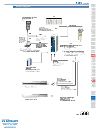
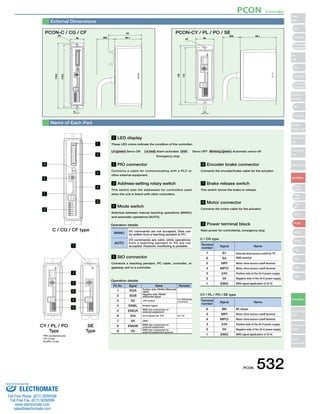
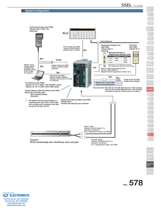
![Item Specifications
RCA/RCA2 Series Actuator
DC24V ±10%
Power Supply Capacity Control power supply (Max. 1.2A) + motor power supply (See the table below)
DC500V 10MΩ or higher
AC500V 1 min.
Max. 30A
XYZ directions 10 to 57Hz, One side amplitude: 0.035mm (continuous), 0.075mm (intermittent)
58 to 150 Hz 4.9 m/s2 (continuous), 9.8 m/s2(intermittent)
1 axis / 2 axis
60W (30W + 30W)
Incremental encoder / Absolute encoder
1mm/sec and up, the maximum depends on actuator specifications
0.01G and up, the maximum depends on the actuator
Program operation / Positioner operation (switchable)
Super SEL language
64 programs
2000 steps
8 points
1500 points
FLASHROM (A system-memory backup battery can be added as an option)
Teaching pendant or PC software
24 input points / 8 output points (NPN or PNP selectable)
Externally supplied 24VDC ± 10%
CB-DS-PIO □□□ (supplied with the controller)
RS232C (D-Sub Half-pitch connector) / USB connector
DeviceNet, CC-Link, ProfiBus
CB-ACS-MA □□□ (Max. 20m)
CB-ACS-PA □□□ (Max. 20m)
Motor overcurrent, Motor driver temperature check, Overload check, Encoder open-circuit check
Soft limit over, system error, battery error, etc.
0 to 40ºC 10 to 95% (non-condensing)
Free from corrosive gases. In particular, there shall be no significant dust.
IP20
Approx. 450g
43 mm (W) x 159 mm (H) x 110 mm (D)
1-Axis specification 2-Axis specification
Table of specifications
Connected actuator
Input Voltage
Dielectric strength voltage
Withstand voltage
Rush current
Vibration resistance
Number of control axes
Maximum total output of connected axis
Position detection method
Speed setting
Acceleration setting
Operating method
Programming language
Number of programs
Number of program steps
Number of multi-tasking programs
Positioning Points
Data memory device
Data input method
Number of I/O
I/O power
PIO cable
Serial communications function
Field Network
Motor Cable
Encoder cable
Protection function
Ambient operating humidity and temperature
Ambient atmosphere
Protection class
Weight
External dimensions
Actuator type
Standard specifications/high
acceleration and deceleration model
Power-saving
Standard specifications/high
acceleration and deceleration model
Power-saving
Rated Max. (Note2) Rated Max. (Note3) Rated Max. (Note2) Rated Max. (Note3)
Motor
power
supply
capacity
(Note1)
RCA
RCA2
10W, 20W [Model symbol: 20] 1.3A 4.4A 1.3A 2.5A 2.6A 8.8A 2.6A 5.0A
30W 1.3A 4.4A 1.3A 2.2A 2.6A 8.8A 2.6A 4.4A
20W [Model symbol: 20S] SA4, RA3, TA5 type dedicated 1.7A 5.1A 1.7A 3.4A 3.4A 10.2A 3.4A 6.8A
RCL
2W 0.8A 4.6A − − 1.6A 9.2A − −
5W 1.0A 6.4A − − 2.0A 12.8A − −
10W 1.3A 6.4A − − 2.6A 12.8A − −
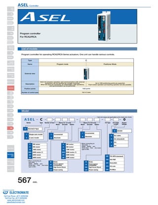
(80) 110
43
ø5
159
151
137
5
3
External Dimensions
ASEL 1-axis controller
ø5
159
151
137
5
3
43
(80) 110
ASEL 2-axis controller
Basic Specifications
Control
specification
Communication Program
General
specifications
(Note 1) For both 1-axis and 2-axis specifications, approx. 30.0A inrush current flows for 5 ms when the control power supply is turned on.
(Note 2) Max. current at accelerating/decelerating
(Note 3) Current reaches the maximum when detecting the servo motor excitation phase at the first servo on after the power is on. (Normal: Approx. 1 to 2 sec., Max.: 10 sec)
(Note 4) Other than motor power supply capacity, it increases 0.5A for control power.
573 ASEL
Slider
Type
Mini
Standard
Controllers
Integrated
Rod
Type
Mini
Standard
Controllers
Integrated
Table/Arm
/Flat Type
Mini
Standard
Gripper/
Rotary Type
Linear Servo
Type
Cleanroom
Type
Splash-Proof
Controllers
PMEC
/AMEC
PSEP
/ASEP
ROBO
NET
ERC2
PCON
ACON
SCON
PSEL
ASEL
SSEL
XSEL
Pulse Motor
Servo Motor
(24V)
Servo Motor
(200V)
Linear
Servo Motor
ASEL Controller
Sold Serviced By:
ELECTROMATE
Toll Free Phone (877) SERVO98
Toll Free Fax (877) SERV099
www.electromate.com
sales@electromate.com](https://image.slidesharecdn.com/iairobocylindercontrollercatalog-141015195025-conversion-gate02/85/Iai-robo-cylinder_controller_catalog-113-320.jpg)
![XSEL Controller
Slider
Type
Mini
Standard
Controllers
Integrated
Rod
Type
Mini
Standard
Controllers
Integrated
Table/Arm
/FlatType
Mini
Standard
Gripper/
Rotary Type
Linear Servo
Type
Cleanroom
Type
Splash-Proof
Controllers
PMEC
/AMEC
PSEP
/ASEP
ROBO
NET
ERC2
PCON
ACON
SCON
PSEL
ASEL
SSEL
XSEL
Pulse Motor
Servo Motor
(24V)
Servo Motor
(200V)
Linear
Servo Motor
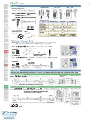
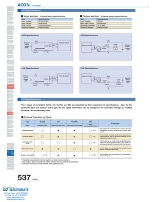
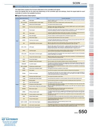
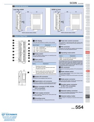
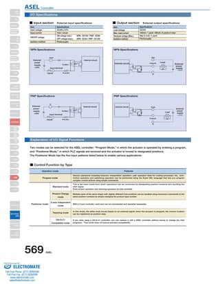
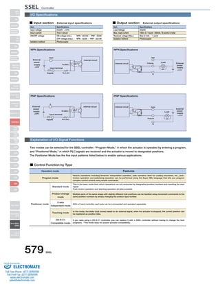
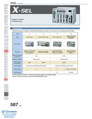
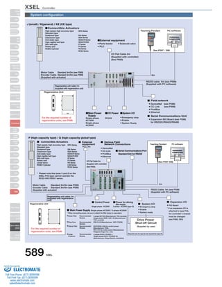
* Notation for 2 - 4 axes depends on the number of axes to be used.
Brake
Creep sensor
High Accel./Decel.
Home sensor/
LS-compatible
Master axis spec
Slave axis spec
Brake
Creep sensor
High Accel./Decel.
Home sensor/
LS-compatible
Master axis spec
Slave axis spec
20W servo motor
30W servo
motor for RCS2
30W servo
motor for RS
60W servo motor
100W servo motor
150W servo motor
200W servo motor
300W servo motor
400W servo motor
600W servo motor
750W servo motor
20W servo motor
30W servo
motor for RCS2
30W servo
motor for RS
60W servo motor
100W servo motor
150W servo motor
200W servo motor
300W servo motor
400W servo motor
600W servo motor
750W servo motor
1000W servo
motor (linear only)
Single-axis model
2-axis model
3-axis model
4-axis model Incremental
Absolute
Incremental
Absolute
(Slot 1) (Slot 2) (Slot 3) (Slot 4)
Input 48/
Output 48 (NPN)
Input 32/
Output 16 (PNP)
Input 48/
Output 48 (PNP)
DeviceNet board
Not used
Input 32/
Output 16 (NPN)
Input 16/
Output 32 (NPN)
Input 48/
Output 48 (NPN)
Single-phase AC100V
Single-phase AC200V
No cable
2m (standard)
3m
5m
Input 32/
Output 16 (PNP)
Input 16/
Output 32 (PNP)
Input 48/
Output 48 (PNP)
CC-Link board
ProfiBus board
Ethernet board
Expansion
SIO type A
Expansion
SIO type B
Expansion
SIO type C
Model
Small type
General type
CE-compatible type
Safety-compliant
type
CE, Safety-compliant
type
Input 32/
Output 16 (NPN)
Series Type Number of Axes
Motor Encoder Option Motor Encoder Option
I/O Cable
Length
Power/
Standard I/O Expansion I/O Voltage
B
C
HA
L
M
S
B
C
HA
L
M
S
20
30D
30R
60
100
150
200
300
400
600
750
20
30D
30R
60
100
150
200
300
400
600
750
1000
1
2
3
4 I
A
I
A
E
N3
P1
P3
DV
N1
N2
N3
1
2
0
2
3
5
P1
P2
P3
CC
PR
ET
SA
SB
SC
J
K
KE
KT
KET
(Specs for 1st axis) (Specs for axis 2 - 4)
N1
* For type J, 1-axis and 2-axis models cannot
be expanded.
On 3-axis and 4-axis models, only
expansion slot 2 can be used.
* The expansion SIO board is only for K type.
(Cannot be used for type J.)
* If you selected DV, CC, PR,
or ET for standard and
expansion I/O select 0 (no
cable) for the I/O cable
length.
* E (Not used) is for
expansion I/O only.
[XSEL-J/K type]
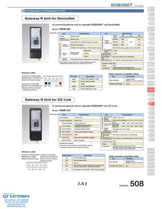
Series Type Number
* Notation for 2 - 6 axes depends on the number of axes to be used.
of Axes Motor Encoder Option Motor Encoder Option
I/O Cable
Length
Power/
(Slot 1) (Slot 2)(Slot 3)(Slot 4)
Standard Voltage
I/O
Expansion I/O
Blank Not used
DV DeviceNet board
CC CC-Link board
PR ProfiBus board
ET Ethernet board
20 20W servo motor
30D 30W servo
motor for RCS2
30R 30W servo
motor for RS
60 60W servo motor
100 100W servo motor
150 150W servo motor
200 200W servo motor
200S For LSA-S10/N15
300 300W servo motor
20S For LSA-N19
400 400W servo motor
600 600W servo motor
750 750W servo motor
20 20W servo motor
30D 30W servo
motor for RCS2
30R 30W servo
motor for RS
60 60W servo motor
100 100W servo motor
150 150W servo motor
200 200W servo motor
200S For LSA-S10/N15
300 300W servo motor
20S For LSA-N19
400 400W servo motor
600 600W servo motor
750 750W servo motor
1000 1000W servo
motor (linear only)
1 Single-axis model
2 2-axis model
3 3-axis model
4 4-axis model
5 5-axis model
6 6-axis model
I Incremental
A Absolute
I Incremental
A Absolute
E Not used
N1
Input 32/
Output 16 (NPN)
N2 Input 16/
Output 32 (NPN)
N3 Input 48/
Output 48 (NPN)
P1 Input 32/
Output 16 (PNP)
P2 Input 16/
Output 32 (PNP)
P3 Input 48/
Output 48 (PNP)
S
With expansion
I/O base
2 Single-phase
AC200V
3 Three-phase
AC200V
2L Dedicated linear
single-phase AC200V
3L Dedicated linear
3-phase AC200V
* Enter 2L or 3L when
operating a linear servo
actuator.
Otherwise, enter 2 or 3.
0 No cable
2 2m (standard)
3 3m
5 5m
P High-capacity type
Q Safety-compliant,
high capacity type
(Specs for 1st axis) (Specs for axis 2 - 6) Dedicated
network slot
B Brake
C Creep sensor
HA High Accel./Decel.
L Home sensor/
LS-compatible
M Master axis spec
S Slave axis spec
B Brake
C Creep sensor
HA High Accel./Decel.
L Home sensor/
LS-compatible
M Master axis spec
S Slave axis spec
* If expansion I/O will not be used,
enter E (not used) for slots 2 to 4.
If you are using expansion I/O,
enter the expansion I/O code in
the desired slot.
If an expansion I/O is specified,
the controller chassis will come
with the expansion I/O base.
(See P592-593)
If you will not be using the
expansion I/O initially but will be
adding it later, specify the chassis
with I/O expansion board, but
specify S for slots 2 to 4.
e.g. Expansion I/O on slot 2, remaining slots unused XSEL-P-2-100A-100A-N1-N1EE-2-3
Expansion I/O base attached, but not the expansion I/O XSEL-P-2-100A-100A-N1-SSS-2-3
[XSEL-P/Q type]
*To specify multiple options, enter them in alphabetical order. (Example: Brake + Home sensor - BL)
Note:
For axis 5 and 6 of XSEL-P/Q type, LSA series, and the RCS2-RA7 / SRA7 series
actuators are unavailable.
XSEL 588
Sold Serviced By:
ELECTROMATE
Toll Free Phone (877) SERVO98
Toll Free Fax (877) SERV099
www.electromate.com
sales@electromate.com](https://image.slidesharecdn.com/iairobocylindercontrollercatalog-141015195025-conversion-gate02/85/Iai-robo-cylinder_controller_catalog-128-320.jpg)
![XSEL Controller
Slider
Type
Mini
Standard
Controllers
Integrated
Rod
Type
Mini
Standard
Controllers
Integrated
Table/Arm
/FlatType
Mini
Standard
Gripper/
Rotary Type
Linear Servo
Type
Cleanroom
Type
Splash-Proof
Controllers
PMEC
/AMEC
PSEP
/ASEP
ROBO
NET
ERC2
PCON
ACON
SCON
PSEL
ASEL
SSEL
XSEL
Pulse Motor
Servo Motor
(24V)
Servo Motor
(200V)
Linear
Servo Motor
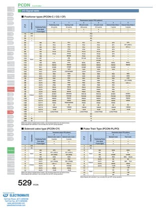
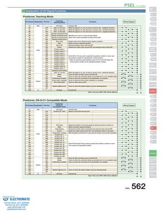
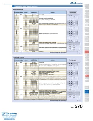
■ Input section External input specification (NPN specification)
Item
Input voltage
Input current
ON/OFF voltage
Isolation method
Externally Connected
Equipment
P24*
■ Input section External input specification (PNP specification)
Input terminal
Standard I/O Signal Table (when N1 or P1 is selected)
Pin No. Classification Port No. Standard Settings
1
2
3
4
5
6
7
8
9
10
11
12
13
14
15
16
17
18
19
20
21
22
23
24
25
26
27
28
29
30
31
32
33
34
35
36
37
38
39
40
41
42
43
44
45
46
47
48
49
50
Input
Output
—
000
001
002
003
004
005
006
007
008
009
010
011
012
013
014
015
016
017
018
019
020
021
022
023
024
025
026
027
028
029
030
031
300
301
302
303
304
305
306
307
308
309
310
311
312
313
314
315
—
(J/P/Q type: 24V connection / K type: NC)
Program start
General Purpose Input
General Purpose Input
General Purpose Input
General Purpose Input
General Purpose Input
General Purpose Input
Program Specification (PRG No. 1)
Program Specification (PRG No. 2)
Program Specification (PRG No. 4)
Program Specification (PRG No. 8)
Program Specification (PRG No. 10)
Program Specification (PRG No. 20)
Program Specification (PRG No. 40)
General Purpose Input
General Purpose Input
General Purpose Input
General Purpose Input
General Purpose Input
General Purpose Input
General Purpose Input
General Purpose Input
General Purpose Input
General Purpose Input
General Purpose Input
General Purpose Input
General Purpose Input
General Purpose Input
General Purpose Input
General Purpose Input
General Purpose Input
General Purpose Input
Alarm Output
Ready Output
Emergency Stop Output
General Purpose Output
General Purpose Output
General Purpose Output
General Purpose Output
General Purpose Output
General Purpose Output
General Purpose Output
General Purpose Output
General Purpose Output
General Purpose Output
General Purpose Output
General Purpose Output
General Purpose Output
(J/P/Q type: 0V connection/K type: NC)
■ Output section External input specification (NPN specification)
Surge
Absorber
Load
J/P/Q type
■ Output section External input specification (PNP specification)
(Note) 400mA is the maximum total load current for each set of the eight ports from
output port No. 300. (The maximum total current output for output port No. 300+n to
Surge
Absorber
Output
terminal
Load
J/P/Q type
Extension I/O Signal Table (when N2 or P2 is selected)
Pin No. Classification Standard Settings
1
2
3
4
5
6
7
8
9
10
11
12
13
14
15
16
17
18
19
20
21
22
23
24
25
26
27
28
29
30
31
32
33
34
35
36
37
38
39
40
41
42
43
44
45
46
47
48
49
50
Input
Output
(J/P/Q type: 24V connection / K type: NC)
General Purpose Input
General Purpose Input
General Purpose Input
General Purpose Input
General Purpose Input
General Purpose Input
General Purpose Input
General Purpose Input
General Purpose Input
General Purpose Input
General Purpose Input
General Purpose Input
General Purpose Input
General Purpose Input
General Purpose Input
General Purpose Input
General Purpose Output
General Purpose Output
General Purpose Output
General Purpose Output
General Purpose Output
General Purpose Output
General Purpose Output
General Purpose Output
General Purpose Output
General Purpose Output
General Purpose Output
General Purpose Output
General Purpose Output
General Purpose Output
General Purpose Output
General Purpose Output
General Purpose Output
General Purpose Output
General Purpose Output
General Purpose Output
General Purpose Output
General Purpose Output
General Purpose Output
General Purpose Output
General Purpose Output
General Purpose Output
General Purpose Output
General Purpose Output
General Purpose Output
General Purpose Output
General Purpose Output
General Purpose Output
(J/P/Q type: 0V connection/K type: NC)
J/P/Q type
J/P/Q type
Extension I/O Signal Table (when N1 or P1 is selected)
Pin No. Classification Standard Settings
1
2
3
4
5
6
7
8
9
10
11
12
13
14
15
16
17
18
19
20
21
22
23
24
25
26
27
28
29
30
31
32
33
34
35
36
37
38
39
40
41
42
43
44
45
46
47
48
49
50
Input
Output
(J/P/Q type: 24V connection / K type: NC)
General Purpose Input
General Purpose Input
General Purpose Input
General Purpose Input
General Purpose Input
General Purpose Input
General Purpose Input
General Purpose Input
General Purpose Input
General Purpose Input
General Purpose Input
General Purpose Input
General Purpose Input
General Purpose Input
General Purpose Input
General Purpose Input
General Purpose Input
General Purpose Input
General Purpose Input
General Purpose Input
General Purpose Input
General Purpose Input
General Purpose Input
General Purpose Input
General Purpose Input
General Purpose Input
General Purpose Input
General Purpose Input
General Purpose Input
General Purpose Input
General Purpose Input
General Purpose Input
General Purpose Output
General Purpose Output
General Purpose Output
General Purpose Output
General Purpose Output
General Purpose Output
General Purpose Output
General Purpose Output
General Purpose Output
General Purpose Output
General Purpose Output
General Purpose Output
General Purpose Output
General Purpose Output
General Purpose Output
General Purpose Output
(J/P/Q type: 0V connection/K type: NC)
I/O wiring drawing
I/O Signal table
Specifications
DC24V ±10%
7mA / circuit
ON Voltage… Min DC16.0V / OFF Voltage… Max DC5.0V
Photocoupler
(1) Non-Voltage Contact (Minimum load around DC5V, 1mA)
(2) Photoelectric Proximity Sensor (NPN Type)
(3) PLC Transistor Output (Open Collector Type)
(4) PLC Contact Output (Minimum Load approx.
DC5V, 1mA)
[Input Circuit]
560Ω
3.3kΩ
Input terminal
+
−
External
power
supply
DC24V
±10%
K type
IO24V Connector
24VIN
I/O Interface
Pin No.1
P24
*
Internal circuit
Item
Load Voltage
Max. load current
Leak current
Isolation method
Externally Connected
Equipment
Specifications
DC24V
100mA / point 400 mA
Peak (Total Current)
Max 0.1mA / point
Photocoupler
(1) Miniature Relay, (2) PLC Input Unit
TD62084 (or equivalent)
[Output Circuit]
10Ω
P24*
D
Output
terminal
K type
IO24V Connector
24VIN
I/O Interface
Pin No.1
P24
IO24V Connector
0V
I/O Interface
Pin No.50
N
*
N*
External
power
supply
DC24V
±10%
Internal circuit
Item
Input voltage
Input current
ON/OFF voltage
Isolation method
Externally Connected Equipment
Specifications
DC24V ±10%
7mA / circuit
ON Voltage… Min DC8V / OFF Voltage… Max DC19V
Photocoupler
(1) Non-Voltage Contact (Minimum load around DC5V, 1mA)
(2) Photoelectric Proximity Sensor (PNP Type)
(3) PLC Transistor Output (Open Collector Type)
(4) PLC Contact Output (Minimum Load approx. DC5V, 1mA)
[Input Circuit]
560Ω
3.3kΩ
N*
External
power
supply
DC24V
±10%
K type
IO24V Connector
0V
I/O Interface
Pin No.50
N
*
Internal circuit
Item
Load Voltage
Max. load current
Leak current
Isolation method
Externally Connected Equipment
Specifications
DC24V
100mA /1 point
400mA / 8 port (Note)
Max 0.1mA / point
Photocoupler
(1) Miniature Relay, (2) PLC Input Unit
TD62784 (or equivalent)
[Output Circuit]
+
−
10Ω
P24*
External
power
supply
DC24V
±10%
N*
K type
IO24V Connector
24VIN
I/O Interface
Pin No.1
P24
IO24V Connector
0V
I/O Interface
Pin No.50
N
*
Internal circuit
No. 300+n+7 must be 400mA, where n = 0 or a multiple of eight.)
XSEL 590
Sold Serviced By:
ELECTROMATE
Toll Free Phone (877) SERVO98
Toll Free Fax (877) SERV099
www.electromate.com
sales@electromate.com](https://image.slidesharecdn.com/iairobocylindercontrollercatalog-141015195025-conversion-gate02/85/Iai-robo-cylinder_controller_catalog-130-320.jpg)
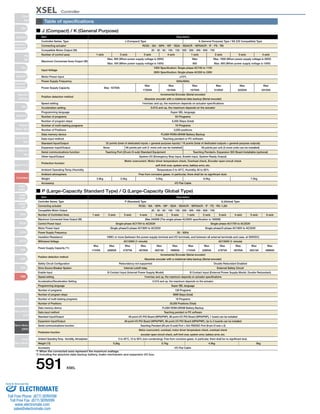
![XSEL Controller
Slider
Type
Mini
Standard
Controllers
Integrated
Rod
Type
Mini
Standard
Controllers
Integrated
Table/Arm
/FlatType
Mini
Standard
Gripper/
Rotary Type
Linear Servo
Type
Cleanroom
Type
Splash-Proof
Controllers
PMEC
/AMEC
PSEP
/ASEP
ROBO
NET
ERC2
PCON
ACON
SCON
PSEL
ASEL
SSEL
XSEL
Pulse Motor
Servo Motor
(24V)
Servo Motor
(200V)
Linear
Servo Motor
■ J (Compact) Type / K (General Purpose) Type
1-axis specification 3/4-axis specification Side View
159.4
143.4 2-ø5
120
296.8
2-ø5
1/2-axis specification 3/4-axis specification
369.4
■ P (high-capacity standard type) / Q (high-capacity global type)
Caution
The specifications of the single phase
200V in Q type is the exterior
dimension of P type.
Brake
I/O Standard only Standard only Standard + Expansion Standard + Expansion
186
180
186
195
186
5
249
3-ø5
49.5 75 75 49.5
249
265
186
180
186
195
186
59.5 75 75 59.5
269
3-ø5
59.5 75 75 59.5
5
269
285
180
195
186
195
186
41 120 120 41
3-ø5
322
41 120 120 41
5
322
338
180
186
195
195
120 51
3-ø5
342
51 120 120 51
5
342
358
284
300
195
186
180
22 120 120 22
5
3-ø5
324
340
195
186
180
42 120 120 42
5
3-ø5
357
373
195
186
180
58.5 120 120 58.5
5
3-ø5
397
413
195
186
180
78.5 120 120 78.5
5
3-ø5
External Dimensions
J type
(Compact Type)
K type
(General Purpose
Type)
The XSEL-P/Q types have different shapes and dimensions in accordance with the controller specifications
(encoder type, with/without brake, and with/without I/O expansion).
The 4 layouts below are available. Confirm dimensions to match the desired type and number of axes.
XSEL-P XSEL-Q
Encoder Incremental
Controllers
Specifications
Single phase
Specifications
3 phases
Specifications
1 to 4 axis
Specifications
5 to 6 axis
Specifications
1 to 4 axis
Specifications
5 to 6 axis
Specifications
Absolute Incremental Absolute
None Yes None Yes
[P Type]
Basic Layout
(Incremental Specification)
2-axis specification
With brake/absolute
unit
Basic Layout
+ I/O expansion base
With brake/absolute unit
+ I/O expansion base
Side View
180
195
49.5 3-ø5
5
49.5 75 75
265
186
5
112.5 112.5 35.9
35.9
186
5
3-ø5
(80) 125.3
195
180
Battery Box (24)
(Applies to
ABS model)
3-ø5
5
186
34.7 150 150 34.7
3-ø5
5
186
77.2
454.4
150 150 77.2
191.9
175.9
120
186
5
180
195
3-ø5
5
285
180
186
3-ø5
5
338
180
186
195
3-ø5
51 120
5
358
(80) 125.3
195
180
Battery Box (24)
(Applies to
ABS model)
284
300
180
195
22
5
3-ø5
324
340
180
195
42 120 120 42
5
3-ø5
357
373
180
195
58.5 120 120 58.5
5
3-ø5
397
413
180
186
78.5 120 120 78.5
5
3-ø5
XSEL 592
Sold Serviced By:
ELECTROMATE
Toll Free Phone (877) SERVO98
Toll Free Fax (877) SERV099
www.electromate.com
sales@electromate.com](https://image.slidesharecdn.com/iairobocylindercontrollercatalog-141015195025-conversion-gate02/85/Iai-robo-cylinder_controller_catalog-132-320.jpg)
![XSEL Controller
Slider
Type
Mini
Standard
Controllers
Integrated
Rod
Type
Mini
Standard
Controllers
Integrated
Table/Arm
/FlatType
Mini
Standard
Gripper/
Rotary Type
Linear Servo
Type
Cleanroom
Type
Splash-Proof
Controllers
PMEC
/AMEC
PSEP
/ASEP
ROBO
NET
ERC2
PCON
ACON
SCON
PSEL
ASEL
SSEL
XSEL
Pulse Motor
Servo Motor
(24V)
Servo Motor
(200V)
Linear
Servo Motor
[Q Type]
Basic Layout
With brake/absolute
XSEL-P XSEL-Q
(Incremental Specification)
Encoder Incremental
Controllers
Specifications
Single phase
Specifications
3 phase
Specifications
unit
Basic Layout
+ I/O expansion base
With brake/absolute unit
+ I/O expansion base
Brake
I/O Standard only Standard only Standard + Expansion Standard + Expansion
1 to 4 axis
Specifications
5 to 6 axis
Specifications
1 to 4 axis
Specifications
5 to 6 axis
Specifications
Absolute Incremental Absolute
None Yes None Yes
Side View
195
186
180
49.5 3-ø5
5
49.5 75 75
249
265
195
186
180
3-ø5
59.5 75 75 59.5
5
269
285
180
195
186
3-ø5
41 120 120 41
5
322
338
180
186
195
3-ø5
51 120
120 51
5
342
358
(80) 125.3
195
180
Battery Box (24)
(Applies to
ABS model)
284
300
195
186
180
22
5
3-ø5
324
340
195
186
180
42 120 120 42
5
3-ø5
357
373
195
186
180
58.5 120 120 58.5
5
3-ø5
397
413
180
195
186
78.5 120 120 78.5
5
3-ø5
206
222
195
186
180
28 75 75 28
5
3-ø5
226
242
186
180
195
38 75 75 38
5
3-ø5
279
295
195
186
180
64.5 75 75 64.5
5
3-ø5
299
315
180
195
186
29.5 120 120 29.5
5
3-ø5
241
257
180
186
195
45.5 75 75 45.5
5
3-ø5
186
20.5 120 120 20.5
180
195
3-ø5
5
186
281 314
297
330
180
195
37 120 120 37
5
3-ø5
354
370
180
195
186
57 120 120 57
5
3-ø5
External dimensional drawing
593 XSEL
Sold Serviced By:
ELECTROMATE
Toll Free Phone (877) SERVO98
Toll Free Fax (877) SERV099
www.electromate.com
sales@electromate.com](https://image.slidesharecdn.com/iairobocylindercontrollercatalog-141015195025-conversion-gate02/85/Iai-robo-cylinder_controller_catalog-133-320.jpg)
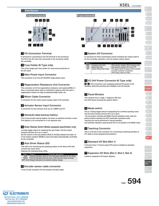
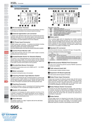
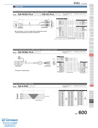

This document provides information on various types of controllers for ROBO cylinders. It discusses positioner type controllers like PMEC/AMEC and PSEP/ASEP which can control positioning to 2-3 positions using the same signals as a solenoid valve. It also covers program type controllers which execute programmed instructions to control actuators and communicate with other devices, allowing for high-level control and interpolated motion of multiple axes. The document provides specifications for different controller models and describes their applications.