Download to read offline
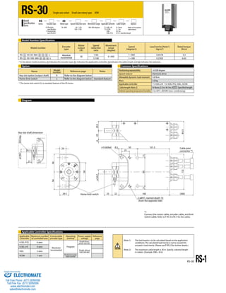
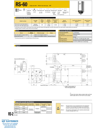
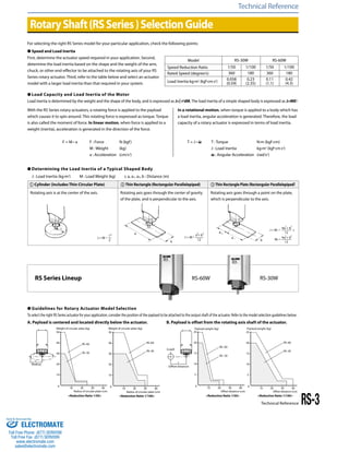
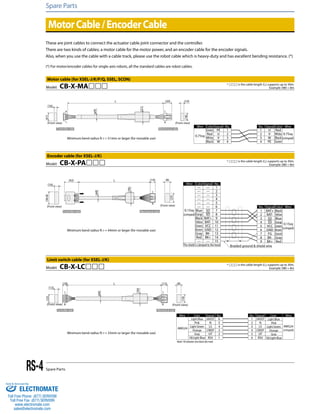
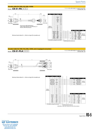

This document provides specifications for the RS series of single-axis rotary robots. It includes details on three robot models: the RS-30, RS-60, and RS-1. Each model varies in motor output power, speed reduction ratios, load capacities, and other technical specifications. The document also provides guidelines for selecting the appropriate robot model based on required speed, load inertia, and payload characteristics. Wiring diagrams and part numbers are included for motor cables, encoder cables, and other spare parts.


