Download to read offline
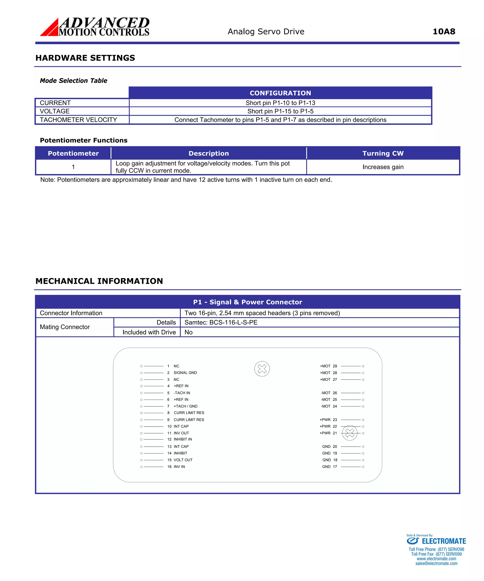

The Analog Servo Drive 10A8 is a PWM servo amplifier designed to drive brush DC motors with a peak current of 10A and continuous current of 6A. It operates from 20-80VDC and has full protection against overcurrent, overheating and short circuits. It can be used with digital controllers or standalone and interfaces with ±10V analog command signals.


