Download to read offline
![Item Specifications
RCA/RCA2 Series Actuator
DC24V ±10%
Power Supply Capacity Control power supply (Max. 1.2A) + motor power supply (See the table below)
DC500V 10MΩ or higher
AC500V 1 min.
Max. 30A
XYZ directions 10 to 57Hz, One side amplitude: 0.035mm (continuous), 0.075mm (intermittent)
58 to 150 Hz 4.9 m/s2 (continuous), 9.8 m/s2(intermittent)
1 axis / 2 axis
60W (30W + 30W)
Incremental encoder / Absolute encoder
1mm/sec and up, the maximum depends on actuator specifications
0.01G and up, the maximum depends on the actuator
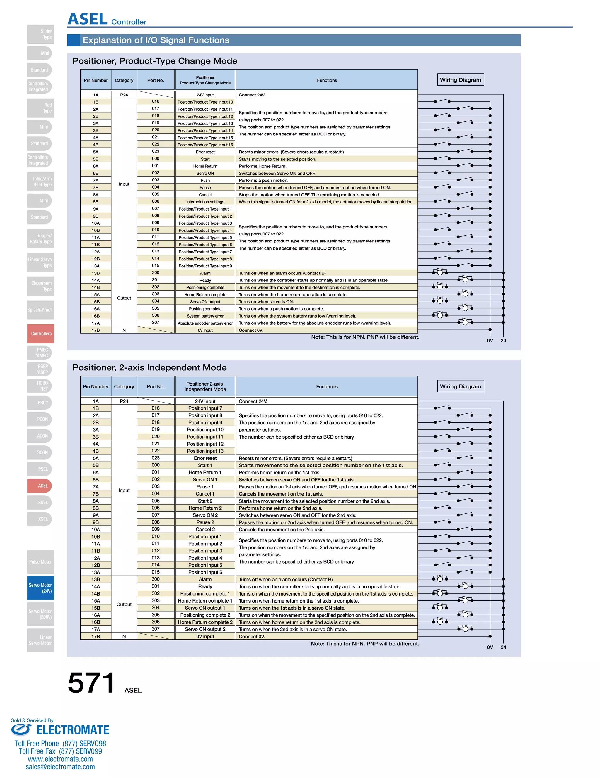
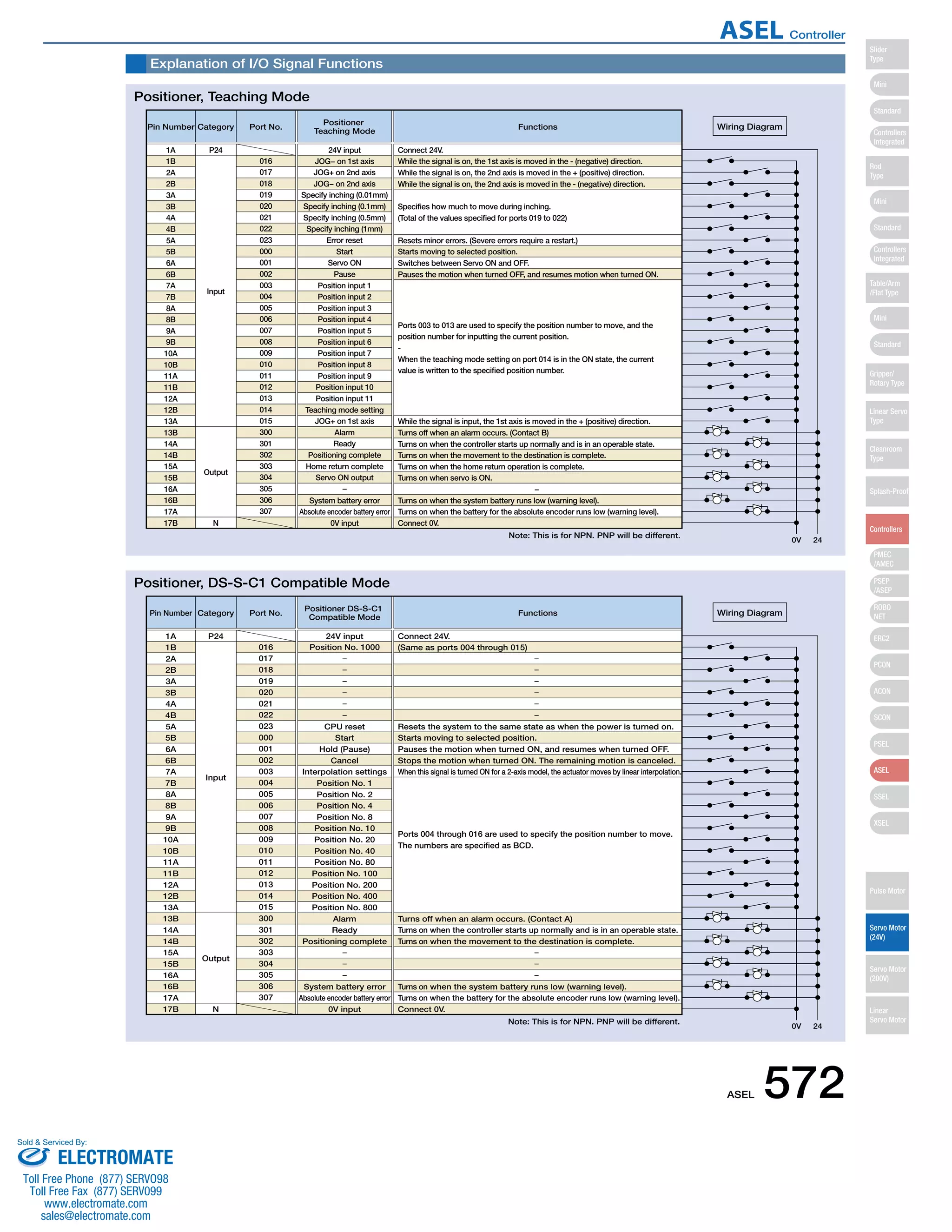
Program operation / Positioner operation (switchable)
Super SEL language
64 programs
2000 steps
8 points
1500 points
FLASHROM (A system-memory backup battery can be added as an option)
Teaching pendant or PC software
24 input points / 8 output points (NPN or PNP selectable)
Externally supplied 24VDC ± 10%
CB-DS-PIO □□□ (supplied with the controller)
RS232C (D-Sub Half-pitch connector) / USB connector
DeviceNet, CC-Link, ProfiBus
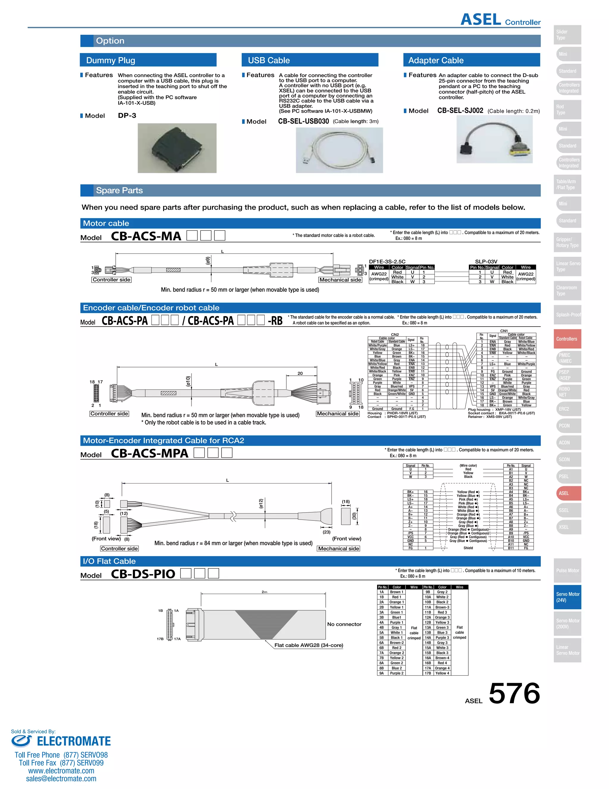
CB-ACS-MA □□□ (Max. 20m)
CB-ACS-PA □□□ (Max. 20m)
Motor overcurrent, Motor driver temperature check, Overload check, Encoder open-circuit check
Soft limit over, system error, battery error, etc.
0 to 40ºC 10 to 95% (non-condensing)
Free from corrosive gases. In particular, there shall be no significant dust.
IP20
Approx. 450g
43 mm (W) x 159 mm (H) x 110 mm (D)
1-Axis specification 2-Axis specification
Table of specifications
Connected actuator
Input Voltage
Dielectric strength voltage
Withstand voltage
Rush current
Vibration resistance
Number of control axes
Maximum total output of connected axis
Position detection method
Speed setting
Acceleration setting
Operating method
Programming language
Number of programs
Number of program steps
Number of multi-tasking programs
Positioning Points
Data memory device
Data input method
Number of I/O
I/O power
PIO cable
Serial communications function
Field Network
Motor Cable
Encoder cable
Protection function
Ambient operating humidity and temperature
Ambient atmosphere
Protection class
Weight
External dimensions
Actuator type
Standard specifications/high
acceleration and deceleration model
Power-saving
Standard specifications/high
acceleration and deceleration model
Power-saving
Rated Max. (Note2) Rated Max. (Note3) Rated Max. (Note2) Rated Max. (Note3)
Motor
power
supply
capacity
(Note1)
RCA
RCA2
10W, 20W [Model symbol: 20] 1.3A 4.4A 1.3A 2.5A 2.6A 8.8A 2.6A 5.0A
30W 1.3A 4.4A 1.3A 2.2A 2.6A 8.8A 2.6A 4.4A
20W [Model symbol: 20S] SA4, RA3, TA5 type dedicated 1.7A 5.1A 1.7A 3.4A 3.4A 10.2A 3.4A 6.8A
RCL
2W 0.8A 4.6A − − 1.6A 9.2A − −
5W 1.0A 6.4A − − 2.0A 12.8A − −
10W 1.3A 6.4A − − 2.6A 12.8A − −
(80) 110
43
ø5
159
151
137
5
3
External Dimensions
ASEL 1-axis controller
ø5
159
151
137
5
3
43
(80) 110
ASEL 2-axis controller
Basic Specifications
Control
specification
Communication Program
General
specifications
(Note 1) For both 1-axis and 2-axis specifications, approx. 30.0A inrush current flows for 5 ms when the control power supply is turned on.
(Note 2) Max. current at accelerating/decelerating
(Note 3) Current reaches the maximum when detecting the servo motor excitation phase at the first servo on after the power is on. (Normal: Approx. 1 to 2 sec., Max.: 10 sec)
(Note 4) Other than motor power supply capacity, it increases 0.5A for control power.
573 ASEL
Slider
Type
Mini
Standard
Controllers
Integrated
Rod
Type
Mini
Standard
Controllers
Integrated
Table/Arm
/Flat Type
Mini
Standard
Gripper/
Rotary Type
Linear Servo
Type
Cleanroom
Type
Splash-Proof
Controllers
PMEC
/AMEC
PSEP
/ASEP
ROBO
NET
ERC2
PCON
ACON
SCON
PSEL
ASEL
SSEL
XSEL
Pulse Motor
Servo Motor
(24V)
Servo Motor
(200V)
Linear
Servo Motor
ASEL Controller
Sold Serviced By:
ELECTROMATE
Toll Free Phone (877) SERVO98
Toll Free Fax (877) SERV099
www.electromate.com
sales@electromate.com](https://image.slidesharecdn.com/iaiaselcontrollerspecsheet-141008205405-conversion-gate02/75/Iai-asel-controller_specsheet-7-2048.jpg)

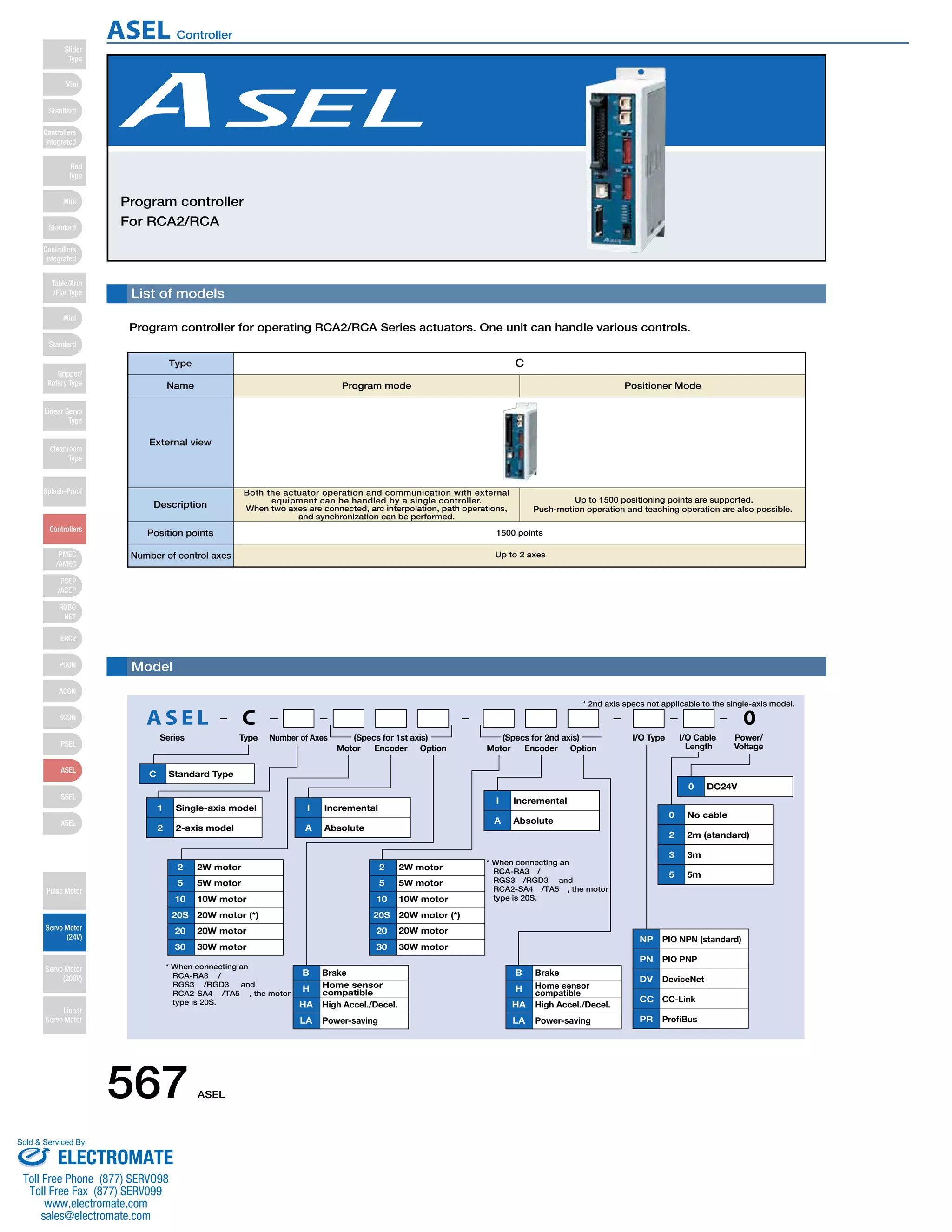
The document describes a program controller for operating RCA2/RCA series actuators. The controller can handle various controls for a single or dual axis system. It supports up to 1500 positioning points and can perform functions like linear/arc interpolation, path operations, and teaching operations through a programmed control mode or PLC input signals in a positioner mode. Key specifications of the controller include support for up to two motor axes, 1500 positioning points, and integrated operation and communication capabilities.


![Vibe Coding vs. Spec-Driven Development [Free Meetup]](https://cdn.slidesharecdn.com/ss_thumbnails/vibecodingvsspecdrivendevelopment-251209105622-43f455e7-thumbnail.jpg?width=640&height=640&fit=bounds)


