Download to read offline

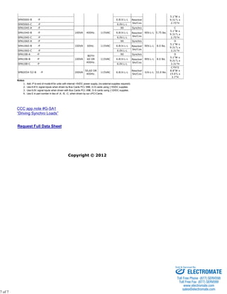

The document describes high power digital to synchro converters and synchro power amplifiers. These devices are used in applications like naval/maritime systems, aircraft, and radar to transmit synchro signals. Models range from 25VA to 300VA and can operate at 60Hz, 400Hz, or both. They are self-powered from an AC reference input, require no external supplies, and offer high efficiency signal transmission with minimal heat generation.


