Download to read offline
![5
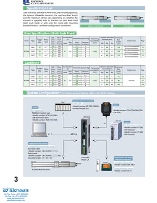
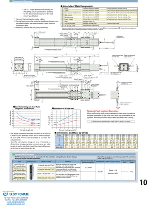
RCP4W-SA5C
ROBO Cylinder Splash-proof slider type Actuator width: 55 mm
Pulse motor Coupling specification
Payload by Acceleration/Deceleration
With the RCP4W series, the payload remains the same
even when the speed is raised.
However, the payload will drop if the acceleration is
raised. Check on the table below.
25
20
15
10
5
4
8
4
6
10
5
3 2
Lead 5
Lead 10
0
0.0 0.1 0.2 0.3 0.4 0.5 0.6
Diagram of Acceleration/Deceleration vs. Payload
1
[Cantilever]
1.5
1
11.2.2
0.7 0.5
2
Lead 5
Lead 10
1.5 1.5
Actuator Specifications
Leads and Payloads Stroke and Maximum Speed
Options Actuator Specifications
(unit: mm/s)
L
Overhang load lengths
L
Allowable load moment directions
~
~
~
~
~
~
~
~
Ma Mb Mc Ma Mc
Model number Lead
(mm)
Maximum horizontal payload (kg) Maximum
push force
(N)
Positioning
repeatability
(mm)
Stroke
Supported on (mm)
both ends Cantilever
RCP4W-SA5C-I-35P-10- 1 -P3- 2 - 3 10 5 1.5 66.9
±0.02
100 to 500
(in 50-mm
RCP4W-SA5C-I-35P-5- 1 -P3- 2 - 3 5 10 2 147.9 increments)
Stroke (mm) Standard price
100 -
150 -
200 -
250 -
300 -
350 -
400 -
450 -
500 -
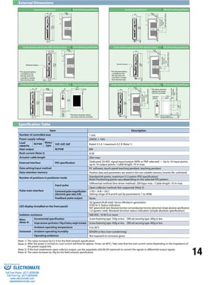
Item Description
Drive system Ball screw φ8 mm, rolled C10
Positioning repeatability ±0.02mm
Lost motion 0.1 mm or less
Static allowable
moment
Supported on both ends Ma: 5.9 N•m Mb: 8.4 N•m Mc: 13.7 N•m
Cantilever Ma: 2.9 N•m Mb: 4.2 N•m Mc: 6.8 N•m
Dynamic allowable
moment (*)
Supported on both ends Ma: 3.4 N•m Mb: 4.9 N•m Mc: 8.0 N•m
Cantilever Ma: 1.7 N•m Mb: 2.5 N•m Mc: 4.0 N•m
Overhang load
length
Supported on both ends 125mm or less
Cantilever 75 mm or less
Protective structure IP65 (with air purge)
Ambient operating temperature, humidity 0 to 40°C, 85% RH or less (Non-condensing)
Name Option code See page Standard price
Cable exit from the left side face A1 P4
-
Cable exit from the right side face A3 P4
Additional alumite coating AL P4 -
Food grade grease (edible grease) GE P4
-
Non-motor side specification NM P4
Ceiling mount (bracket mounted on the left) HFL P4
Ceiling mount (bracket mounted on the right) - HFR P4
Wall mount sideways on the left TFL P4
Wall mount sideways on the right TFR P4
(*) Based on 5,000 km of traveling life
Notes
on
selection
(1) This actuator is designed exclusively for horizontal installation. It cannot be installed vertically.
When hanging the actuator from the ceiling or mounting it on the wall, be sure to do so using
an optional dedicated bracket.
(2) The payload varies depending on the acceleration/deceleration. The upper limit of
acceleration/deceleration is 0.6 G.
(3) The cable joint connector is not splash-proof, so install the connector in a location where it
will not come in contact with water.
(4) Refer to the page at right for the air tube length and air flow rate when implementing air purge.
100 to 500
(in 50-mm increments)
10 330
5 165
35P: Pulse motor
I: Incremental size 35
specification
P3:PCON-CA Refer to the option
list below.
100 : 100mm
500 : 500mm
(Can be set in
50-mm
increments.)
* Also select code “I”
for the simple absolute
specification.
10 : 10mm
5 : 5mm
SA5C
Type
I
Encoder
type
35P
Motor type
P3
Applicable
Lead Stroke controller Cable length Options
RCP4W
Series
8
6
4
2
0
0.0 0.1 0.2 0.3 0.4 0.5 0.6
* The RCP4W can be
operated only with
the PCON-CA
Model
Specification
Items
~
N: None
P: 1 m
S: 3 m
M: 5 m
X : Length designation
R : Robot cable
Diagram of Acceleration/Deceleration vs. Payload
[Supported at Both Ends]
Payload (kg)
Payload (kg)
Acceleration/deceleration (G)
Acceleration/deceleration (G)
Legend 1 Stroke 2 Cable length 3 Options
Stroke
Lead
Type Cable symbol Standard price
Standard type
P (1m) -
S (3m) -
M (5m) -
Special length
X06 (6m) X10 (10m) -
X11 (11m) X15 (15m) -
X16 (16m) X20 (20m) -
Robot cable
R01 (1m) R03 (3m) -
R04 (4m) R05 (5m) -
R06 (6m) R10 (10m) -
R11 (11m) R15 (15m) -
R16 (16m) R20 (20m) -
1 Stroke
3
2 Cable length
Sold & Serviced By:
ELECTROMATE
Toll Free Phone (877) SERVO98
Toll Free Fax (877) SERV099
www.electromate.com
sales@electromate.com](https://image.slidesharecdn.com/iaircp4wspecsheet-141014122242-conversion-gate01/85/Iai-rcp4-w_specsheet-6-320.jpg)
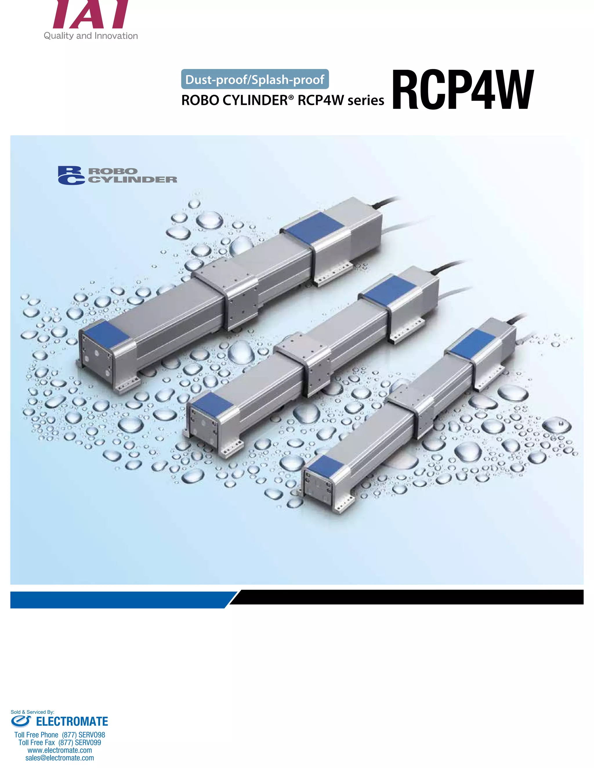
![7
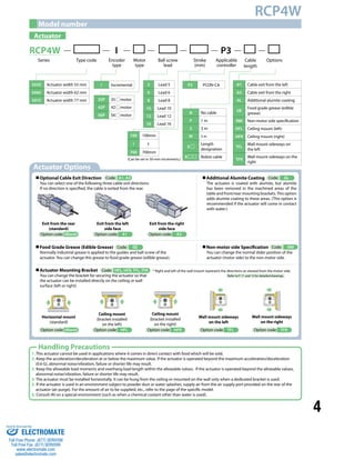
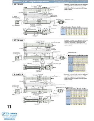
RCP4W-SA6C
ROBO Cylinder Splash-proof slider type Actuator width: 62 mm
Pulse motor Coupling specification
Payload by Acceleration/Deceleration
With the RCP4W series, the payload remains the same
even when the speed is raised.
However, the payload will drop if the acceleration is
raised. Check on the table below.
Notes
on
selection
(1) This actuator is designed exclusively for horizontal installation. It cannot be installed vertically.
When hanging the actuator from the ceiling or mounting it on the wall, be sure to do so using
an optional dedicated bracket.
(2) The payload varies depending on the acceleration/deceleration. The upper limit of
acceleration/deceleration is 0.6 G.
(3) The cable joint connector is not splash-proof, so install the connector in a location where it
will not come in contact with water.
(4) Refer to the page at right for the air tube length and air flow rate when implementing air purge.
25
20
15
10
5
0
15
12
9
Lead6
Lead162
7.5 7.5 6
5.5
4 3
0.0 0.1 0.2 0.3 0.4 0.5 0.6
Diagram of Acceleration/Deceleration vs. Payload
[Cantilever]
3.5
2.5
2.5
1.5
3
2
4.5
3
4.5
3
Lead6
Lead12
Actuator Specifications
Leads and Payloads Stroke and Maximum Speed
Options
Actuator Specifications
(unit: mm/s)
L
Overhang load lengths
L
Allowable load moment directions
~
~
~
~
~
~
~
~
Ma Mb Mc Ma Mc
Model number Lead
(mm)
Maximum horizontal payload (kg) Maximum
push force
(N)
Positioning
repeatability
(mm)
Stroke
Supported on (mm)
both ends Cantilever
RCP4W-SA6C-I-42P-12- 1 -P3- 2 - 3 12 7.5 3 82.8
±0.02
100 to 600
(in 50-mm
RCP4W-SA6C-I-42P-6- 1 -P3- 2 - 3 6 15 4.5 179.5 increments)
Stroke (mm) Standard price
100 -
150 -
200 -
250 -
300 -
350 -
400 -
450 -
500 -
550 -
600 -
Item Description
Drive system Ball screw φ10 mm, rolled C10
Positioning repeatability ±0.02mm
Lost motion 0.1 mm or less
Static allowable
moment
Supported on both ends Ma: 8.5 N•m Mb: 12.2 N•m Mc: 19.9 N•m
Cantilever Ma: 4.3 N•m Mb: 6.1 N•m Mc: 10.0 N•m
Dynamic allowable
moment (*)
Supported on both ends Ma: 4.7 N•m Mb: 6.7 N•m Mc: 11.0 N•m
Cantilever Ma: 2.4 N•m Mb: 3.4 N•m Mc: 5.5 N•m
Overhang load
length
Supported on both ends 150mm or less
Cantilever 90 mm or less
Protective structure IP65 (with air purge)
Ambient operating temperature, humidity 0 to 40°C, 85% RH or less (Non-condensing)
Name Option code See page Standard price
Cable exit from the left side face A1 P4
-
Cable exit from the right side face A3 P4
Additional alumite coating AL P4 -
Food grade grease (edible grease) GE P4
-
Non-motor side specification NM P4
Ceiling mount (bracket mounted on the left) HFL P4
Ceiling mount (bracket mounted on the right) - HFR P4
Wall mount sideways on the left TFL P4
Wall mount sideways on the right TFR P4 (*) Based on 5,000 km of traveling life
100 to 600
(in 50-mm increments)
12 400
6 200
I: Incremental
specification
P3:PCON-CA Refer to the option
list below.
100 : 100mm
600 : 600mm
(Can be set in
50-mm
increments.)
* Also select code “I”
for the simple absolute
specification.
SA6C
Type
I
Encoder
type
42P
Motor type
P3
Applicable
Lead Stroke controller Cable length Options
RCP4W
Series
8
6
4
2
0
0.0 0.1 0.2 0.3 0.4 0.5 0.6
* The RCP4W can be
operated only with
the PCON-CA
Model
Specification
Items
~
N: None
P: 1 m
S: 3 m
M: 5 m
X : Length designation
R : Robot cable
Diagram of Acceleration/Deceleration vs. Payload
[Supported at Both Ends]
Payload (kg)
Payload (kg)
Acceleration/deceleration (G)
Acceleration/deceleration (G)
Legend 1 Stroke 2 Cable length 3 Options
Stroke
Lead
Type Cable symbol Standard price
Standard type
P (1m) -
S (3m) -
M (5m) -
Special length
X06 (6m) X10 (10m) -
X11 (11m) X15 (15m) -
X16 (16m) X20 (20m) -
Robot cable
R01 (1m) R03 (3m) -
R04 (4m) R05 (5m) -
R06 (6m) R10 (10m) -
R11 (11m) R15 (15m) -
R16 (16m) R20 (20m) -
1 Stroke
3
2 Cable length
42P: Pulse motor
size 42
12 : 12mm
6 : 6mm
Sold & Serviced By:
ELECTROMATE
Toll Free Phone (877) SERVO98
Toll Free Fax (877) SERV099
www.electromate.com
sales@electromate.com](https://image.slidesharecdn.com/iaircp4wspecsheet-141014122242-conversion-gate01/85/Iai-rcp4-w_specsheet-8-320.jpg)
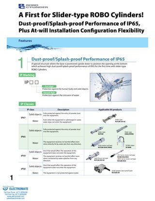
![9
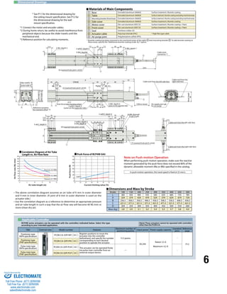
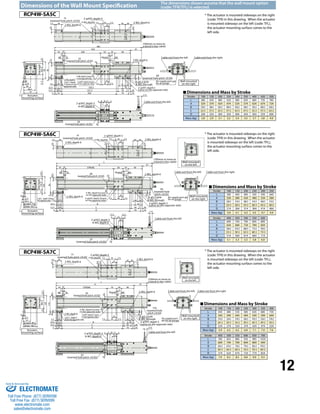
RCP4W-SA7C
ROBO Cylinder Splash-proof slider type Actuator width: 77 mm
Pulse motor Coupling specification
Payload by Acceleration/Deceleration
With the RCP4W series, the payload remains the same
even when the speed is raised.
However, the payload will drop if the acceleration is
raised. Check on the table below.
25
20
15
10
5
0
20
16
12
10 8
4
6
8
Lead68
Lead16
0.0 0.1 0.2 0.3 0.4 0.5 0.6
Diagram of Acceleration/Deceleration vs. Payload
4
3
[Cantilever]
6
4
7
5
4.5
7
4.5
3.5
Lead8
Lead16
Actuator Specifications
Leads and Payloads Stroke and Maximum Speed
Options
Actuator Specifications
(unit: mm/s)
L
Overhang load lengths
L
Allowable load moment directions
~
~
~
~
~
~
~
~
Ma Mb Mc Ma Mc
Model number Lead
(mm)
Maximum horizontal payload (kg) Maximum
push force
(N)
Positioning
repeatability
(mm)
Stroke
Supported on (mm)
both ends Cantilever
RCP4W-SA7C-I-56P-16- 1 -P3- 2 - 3 16 10 4.5 161.9
±0.02
100 to 700
(in 50-mm
RCP4W-SA7C-I-56P-8- 1 -P3- 2 - 3 8 20 7 337.9 increments)
Stroke (mm) Standard price
100 -
150 -
200 -
250 -
300 -
350 -
400 -
450 -
500 -
550 -
600 -
650 -
700 -
Item Description
Drive system Ball screw φ12 mm, rolled C10
Positioning repeatability ±0.02mm
Lost motion 0.1 mm or less
Static allowable
moment
Supported on both ends Ma: 11.7N•m Mb: 16.6 N•m Mc: 31.8 N•m
Cantilever Ma: 5.8 N•m Mb: 8.3 N•m Mc: 15.9 N•m
Dynamic allowable
moment (*)
Supported on both ends Ma: 6.1 N•m Mb: 8.8 N•m Mc: 16.8 N•m
Cantilever Ma:3.1 N•m Mb: 4.4 N•m Mc: 8.4 N•m
Overhang load
length
Supported on both ends 175 mm or less
Cantilever 105 mm or less
Protective structure IP65 (with air purge)
Ambient operating temperature, humidity 0 to 40°C, 85% RH or less (Non-condensing)
Name Option code See page Standard price
Cable exit from the left side face A1 P4
-
Cable exit from the right side face A3 P4
Additional alumite coating AL P4 -
Food grade grease (edible grease) GE P4
-
Non-motor side specification NM P4
Ceiling mount (bracket mounted on the left) HFL P4
Ceiling mount (bracket mounted on the right) - HFR P4
Wall mount sideways on the left TFL P4
Wall mount sideways on the right TFR P4
(*) Based on 5,000 km of traveling life
Notes
on
selection
(1) This actuator is designed exclusively for horizontal installation. It cannot be installed vertically.
When hanging the actuator from the ceiling or mounting it on the wall, be sure to do so using
an optional dedicated bracket.
(2) The payload varies depending on the acceleration/deceleration. The upper limit of
acceleration/deceleration is 0.6 G.
(3) The cable joint connector is not splash-proof, so install the connector in a location where it
will not come in contact with water.
(4) Refer to the page at right for the air tube length and air flow rate when implementing air purge.
100 to 700
(in 50-mm increments)
16 530
8 265
I: Incremental
specification
P3:PCON-CA Refer to the option
list below.
100 : 100mm
700 : 700mm
(Can be set in
50-mm
increments.)
* Also select code “I”
for the simple absolute
specification.
SA7C
Type
I
Encoder
type
56P
Motor type
P3
Applicable
Lead Stroke controller Cable length Options
RCP4W
Series
8
6
4
2
0
0.0 0.1 0.2 0.3 0.4 0.5 0.6
* The RCP4W can be
operated only with
the PCON-CA
Model
Specification
Items
~
N: None
P: 1 m
S: 3 m
M: 5 m
X : Length designation
R : Robot cable
Diagram of Acceleration/Deceleration vs. Payload
[Supported at Both Ends]
Payload (kg)
Payload (kg)
Acceleration/deceleration (G)
Acceleration/deceleration (G)
Legend 1 Stroke 2 Cable length 3 Options
Stroke
Lead
Type Cable symbol Standard price
Standard type
P (1m) -
S (3m) -
M (5m) -
Special length
X06 (6m) X10 (10m) -
X11 (11m) X15 (15m) -
X16 (16m) X20 (20m) -
Robot cable
R01 (1m) R03 (3m) -
R04 (4m) R05 (5m) -
R06 (6m) R10 (10m) -
R11 (11m) R15 (15m) -
R16 (16m) R20 (20m) -
1 Stroke
3
2 Cable length
56P: Pulse motor
size 56
16 : 16mm
8 : 8mm
Sold & Serviced By:
ELECTROMATE
Toll Free Phone (877) SERVO98
Toll Free Fax (877) SERV099
www.electromate.com
sales@electromate.com](https://image.slidesharecdn.com/iaircp4wspecsheet-141014122242-conversion-gate01/85/Iai-rcp4-w_specsheet-10-320.jpg)

The document describes the RCP4W series of dust-proof/splash-proof slider-type robot cylinders. Key points: - It achieves an IP65 level of dust-proof and splash-proof performance for the first time in a slider-type cylinder by positioning the base upside-down with the opening on the bottom. - Models include the RCP4W-SA5C, SA6C, and SA7C, which have actuator widths of 55mm, 62mm, and 77mm respectively. - Flexible installation options include wall mounting, ceiling mounting, and ability to install on any side of a table for increased configuration flexibility.


