Download to read offline
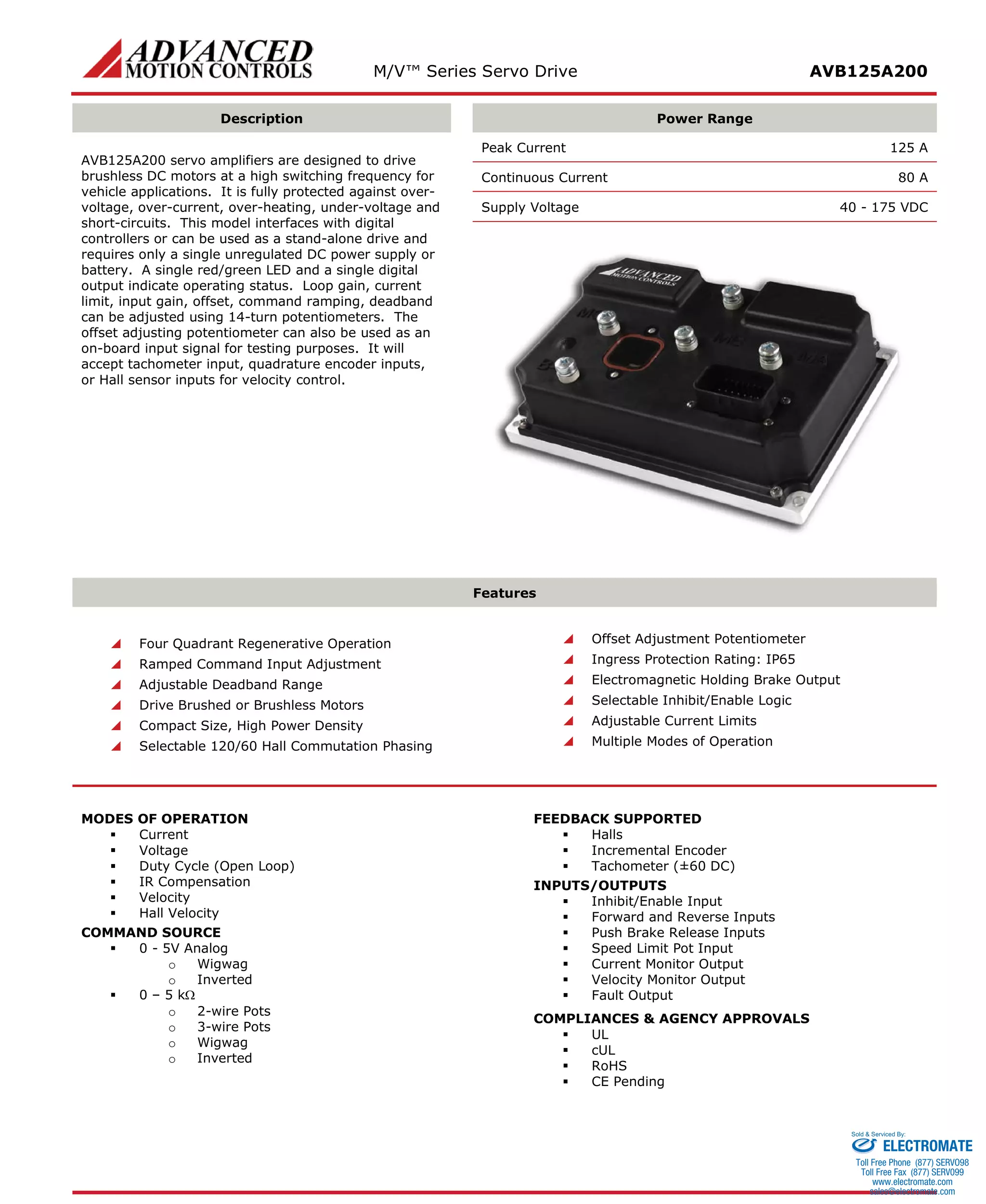
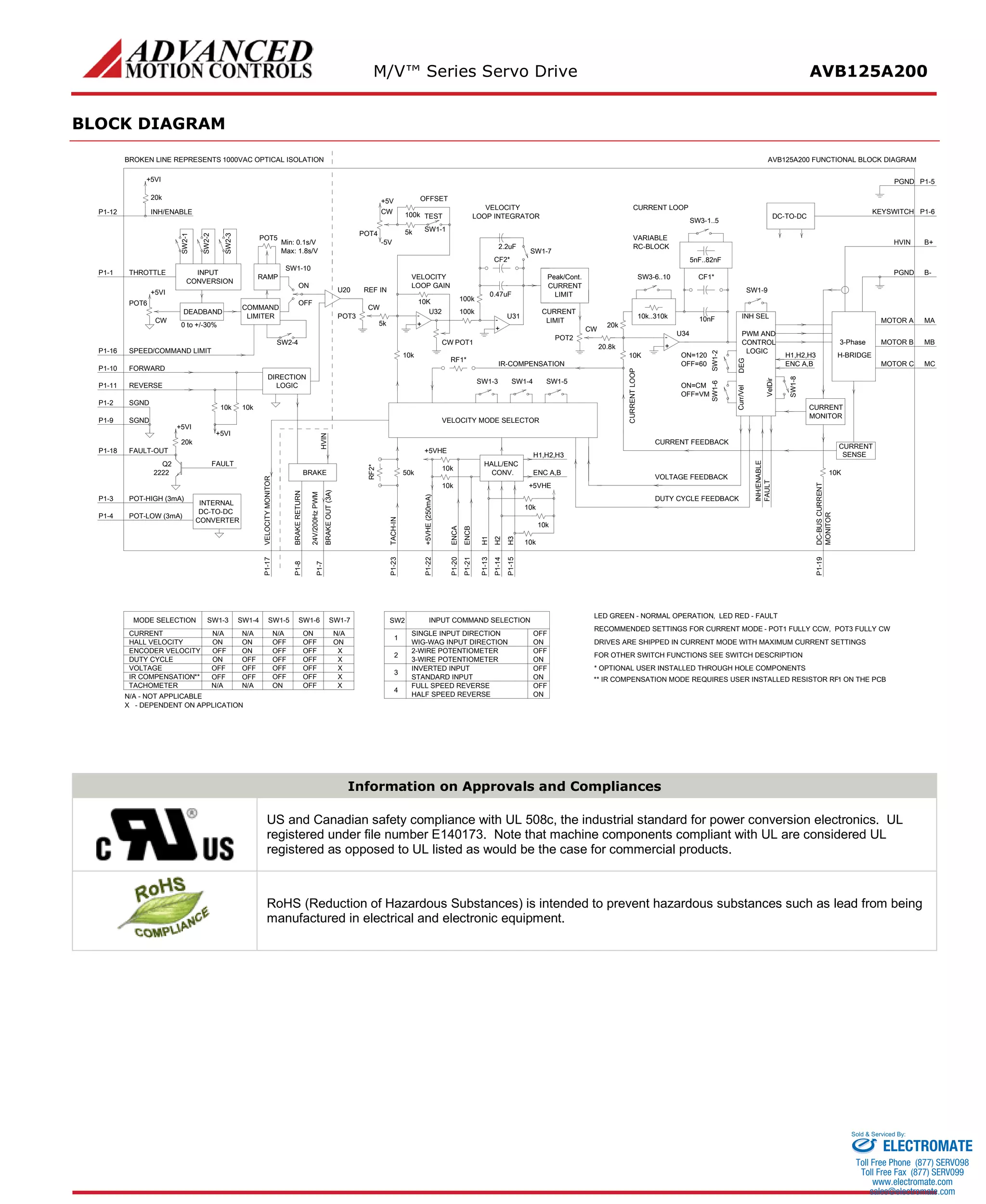
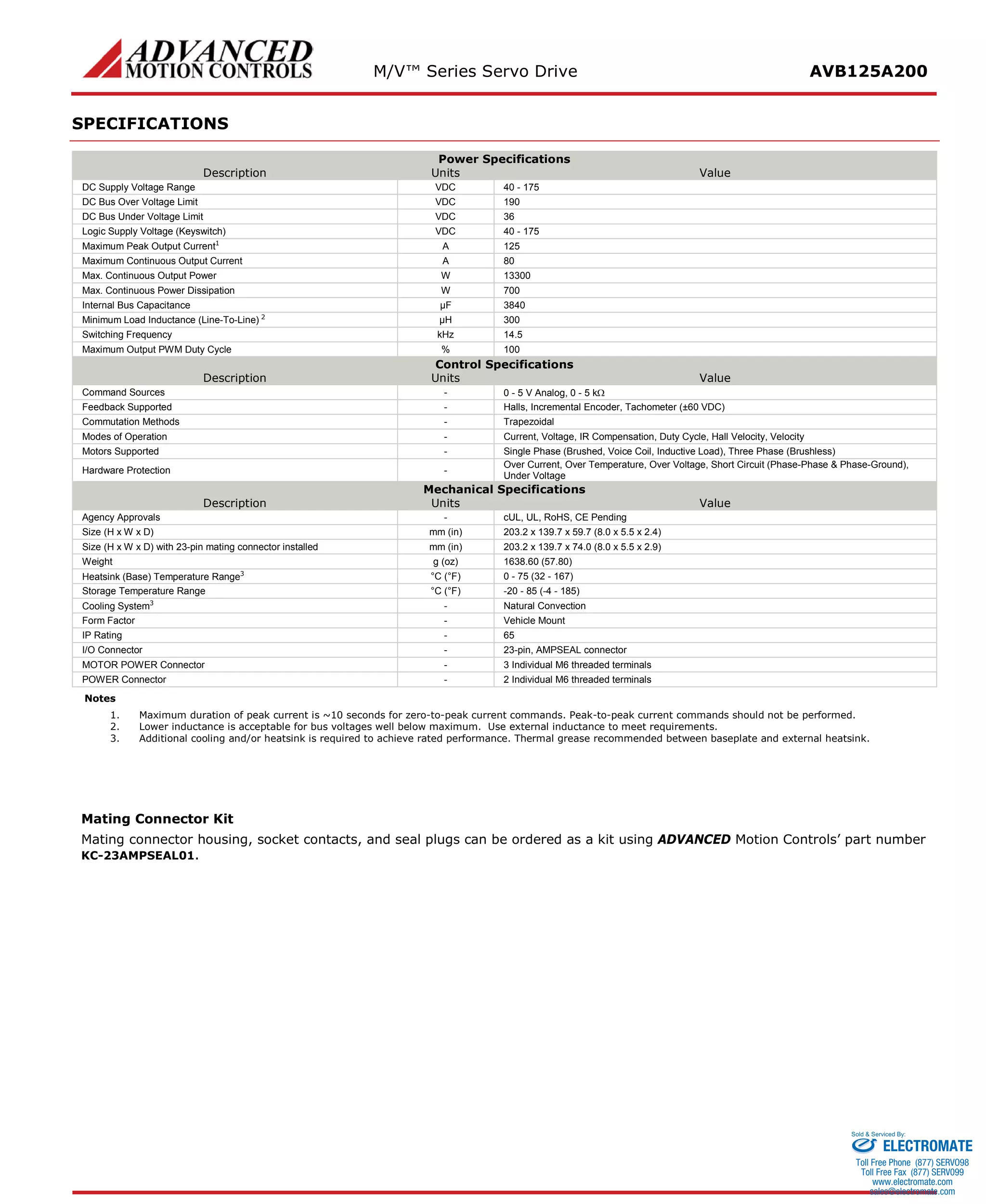
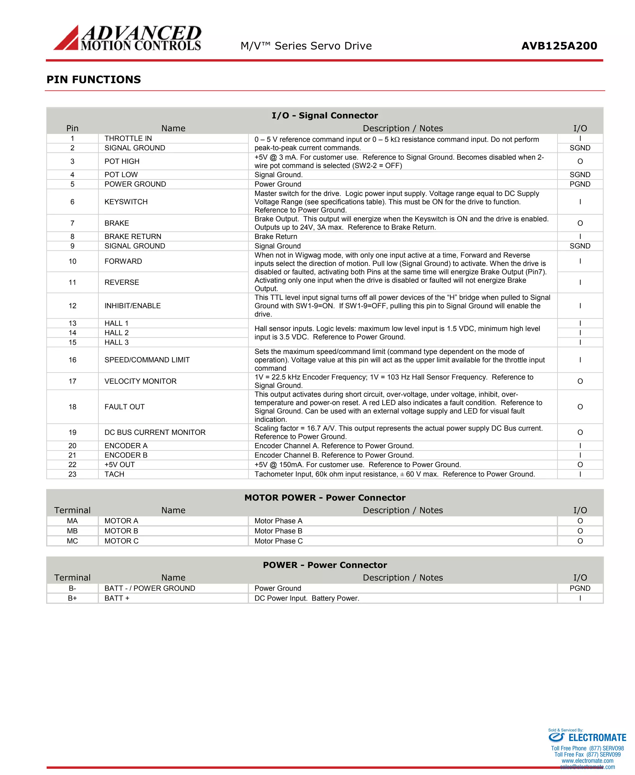
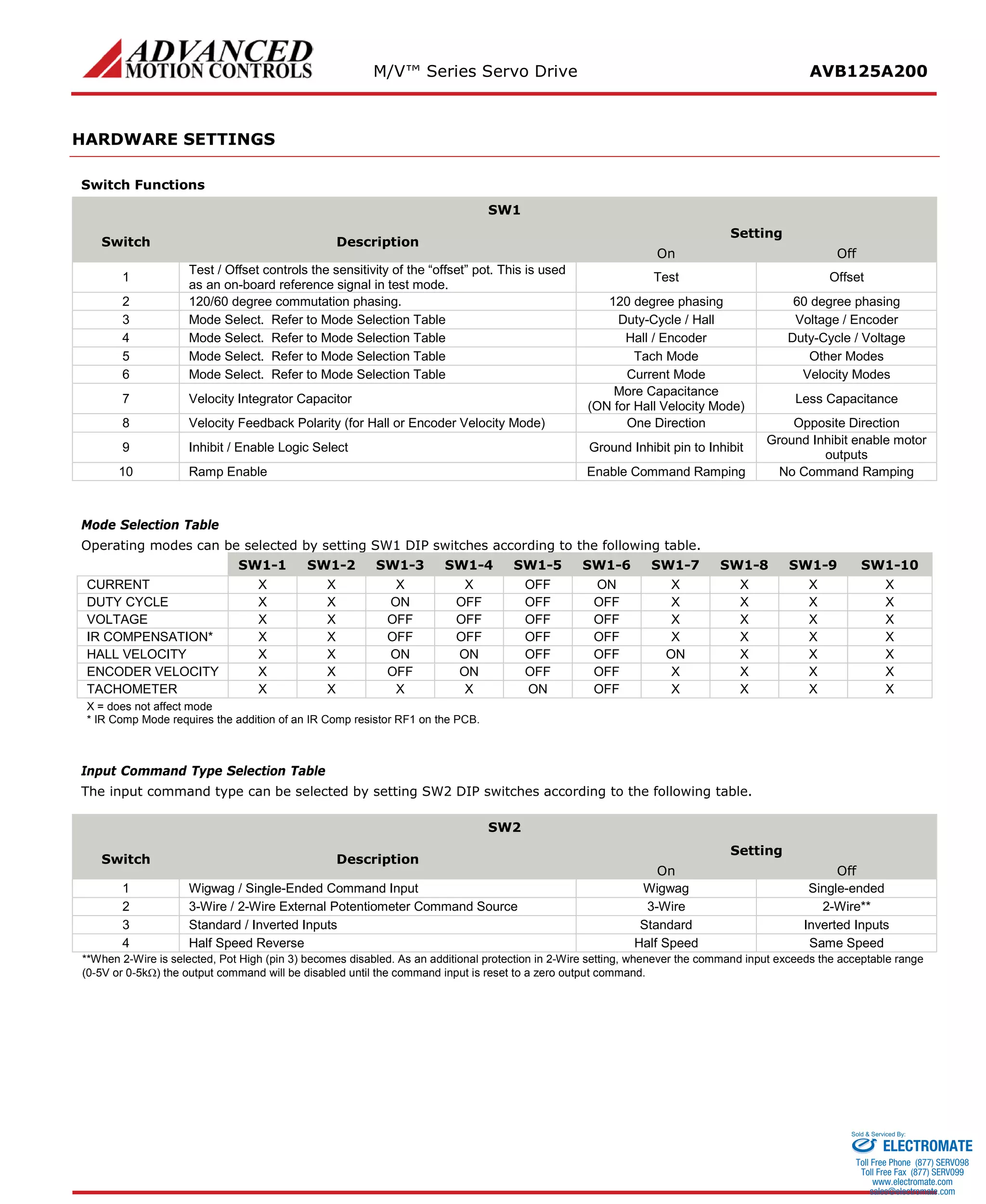
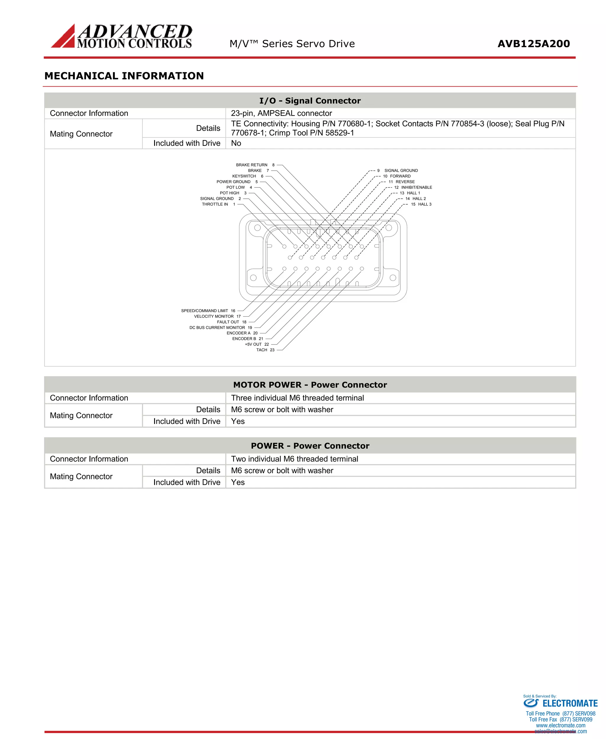
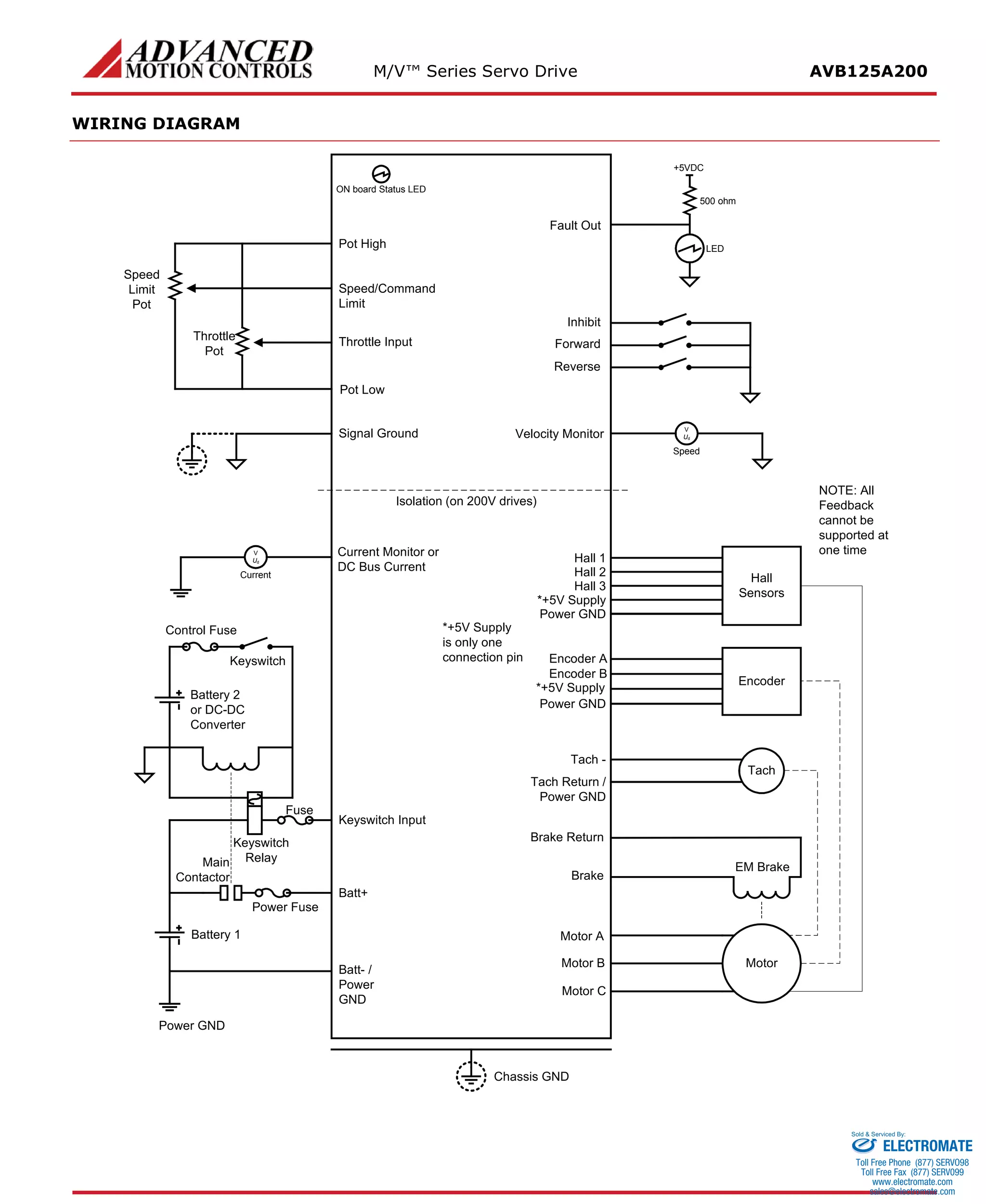
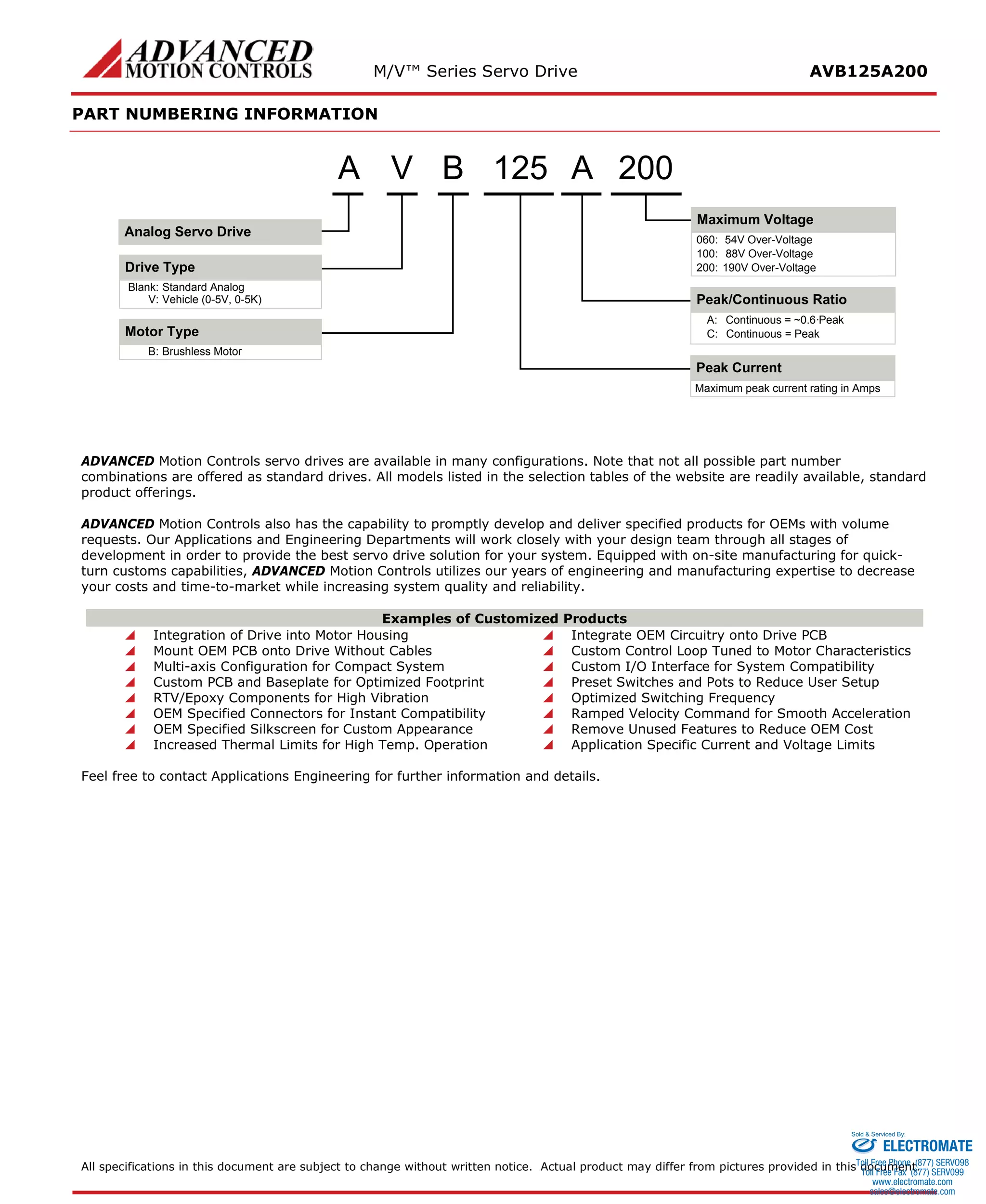

This document provides specifications for the M/VTM Series Servo Drive AVB125A200. It is designed to drive brushless DC motors for vehicle applications with a peak current of 125A and continuous current of 80A. It accepts analog and potentiometer command inputs and feedback from Hall sensors, encoders, or tachometers. Modes of operation include current, voltage, velocity control and more which are selected using onboard DIP switches and potentiometers.


![Vibe Coding vs. Spec-Driven Development [Free Meetup]](https://cdn.slidesharecdn.com/ss_thumbnails/vibecodingvsspecdrivendevelopment-251209105622-43f455e7-thumbnail.jpg?width=640&height=640&fit=bounds)

