Download to read offline

![ACON Controller
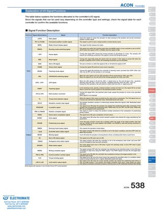
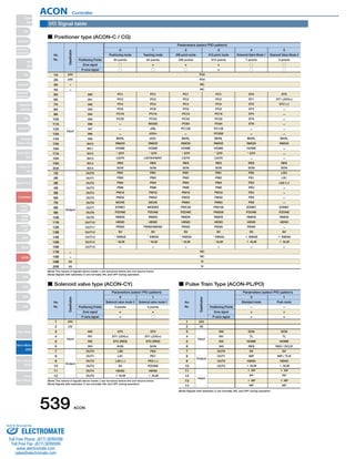
Command Pulse Input State
Command pulse train state Input terminal During forward operation During reversed operation
Table of specifications
Motor
Power
Supply
Capacity
(Note 2)
Low High
High Low
Forward pulse train
Reversed pulse train
The forward pulse train causes the motor to rotate forward, and the reverse pulse train causes the motor to rotate in reverse.
Pulse train
Symbols
The command pulse is used for the amount of motor rotation, and the command symbol is used for rotational direction.
A/B phase pulse train
An A/B phase pulse with a 90° phase difference (multiplier is 4) is used to generate commands for the amount of rotation and rotational direction.
Forward pulse train
Reversed pulse train
Pulse train
Symbols
A/B phase pulse train
PP・/PP
NP・/NP
PP・/PP
NP・/NP
PP・/PP
NP・/NP
PP・/PP
NP・/NP
PP・/PP
NP・/NP
PP・/PP
NP・/NP
Positive logic Negative logic
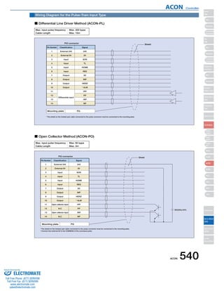
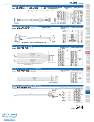
Item Specifications
Positioner type Solenoid valve type
— 64 points
4 input points / 6 output points 4 input points/4 output points None
CB-PACPU-PIO □□□
Differential line driver Open collector —
— Max. 200 kpps Max. 60 kpps —
External
ON/OFF terminal signal inside the power terminal for brake release
XYZ directions 10 to 57Hz, One side amplitude: 0.035mm (continuous), 0.075mm (intermittent)
58 to 150 Hz 4.9 m/s2 (continuous), 9.8 m/s2 (intermittent)
Standard specifications/high acceleration and deceleration model
Rated [A] Max. [A]
Power-saving model
—
Rated [A] Max. [A]
RCA Series Actuator
1-axis
EEPROM
40-pin connector 12-pin connector 14-pin connector None
16 input points/16 output points
External supply DC24V±10%
RS485 1ch
CB-PAC-PIO □□□ CB-PACY-PIO □□□ CB-RCB-CTL002
Controller type
Actuator
RCA
RCA2
RCL
Motor
1.3
1.3
1.3
1.7
0.8
1.0
1.3
1.3
1.3
1.3
1.7
2.5
2.5
2.2
3.4
10W
20W [Model symbol: 20]
30W
20W [Model symbol: 20S]
SA4, RA3, TA5
Type dedicated
2W
5W
10W
4.4
4.4
4.4
5.1
4.6
6.4
6.4
Connected actuator
Number of control axes
Operating method
Positioning Points
Backup memory
I/O connector
Number of I/O
I/O power
Serial Communication
Peripheral device communication cable
Command pulse train input method
Max. input pulse frequency (Note 1)
Position detection method
Drive-source cutoff relay at emergency stop
Forced release of electromagnetic brake
Input Voltage
Dielectric strength voltage
Vibration resistance
Ambient operating temperature
Ambient operating humidity
Ambient operating atmosphere
Protection class
Weight
C CG CY PL PO SE
Pulse train input type Serial communication type
512 points 3 points
—
Incremental encoder
Integrated
Brake release switch ON/OFF
DC24V ± 10%
DC500V 1MΩ
0 ~ 40°C
10 - 95% (non-condensing)
Without corrosive gases
IP20
Approx. 300g Approx. 130g
(Note 1) With the open collector specification, keep the maximum input frequency to 60 kpps or below to prevent malfunction. For applications exceeding 60kpps, use the differential line driver.
(Note 2) Other than motor power supply capacity, increase 0.5A as control power supply. Inrush current of approx. 5 to 12 times the rated current occurs within 1 to 2 msec from
turning the power on. The inrush current changes depending on the power supply line impedance.
541 ACON
Slider
Type
Mini
Standard
Controllers
Integrated
Rod
Type
Mini
Standard
Controllers
Integrated
Table/Arm
/FlatType
Mini
Standard
Gripper/
Rotary Type
Linear Servo
Type
Cleanroom
Type
Splash-Proof
Controllers
PMEC
/AMEC
PSEP
/ASEP
ROBO
NET
ERC2
PCON
ACON
SCON
PSEL
ASEL
SSEL
XSEL
Pulse Motor
Servo Motor
(24V)
Servo Motor
(200V)
Linear
Servo Motor
Sold Serviced By:
ELECTROMATE
Toll Free Phone (877) SERVO98
Toll Free Fax (877) SERV099
www.electromate.com
sales@electromate.com](https://image.slidesharecdn.com/iaiaconcontrollerspecsheet-141008205403-conversion-gate01/85/Iai-acon-controller_specsheet-7-320.jpg)

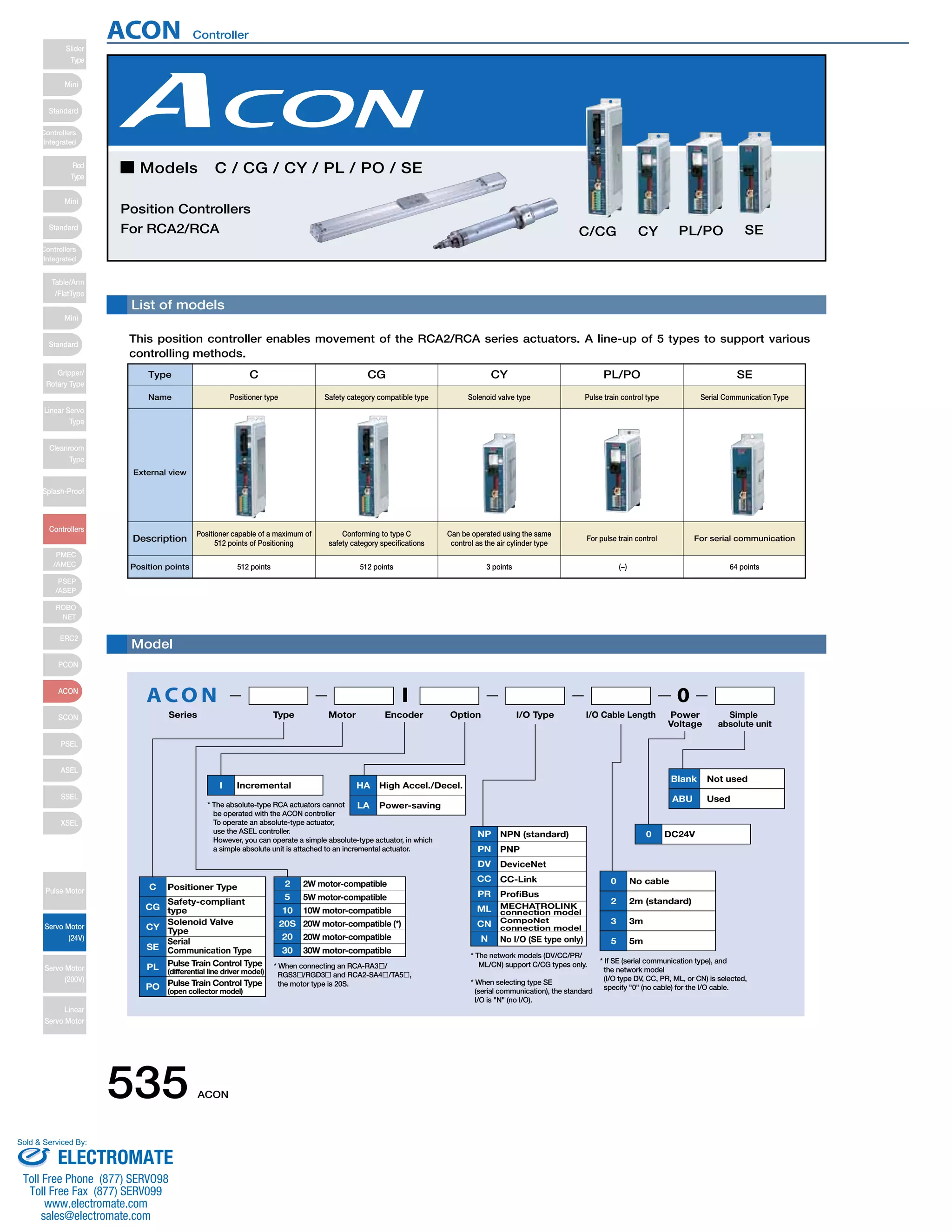
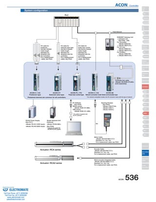
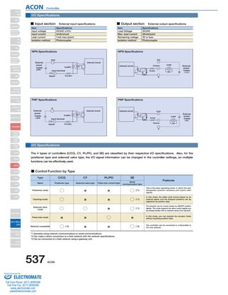
This document provides information on the ACON position controller models C/CG/CY/PL/PO/SE. It lists the 5 controller types and their functions. The C/CG types are positioner controllers that can control up to 512 positioning points. The CY type controls solenoid valves. The PL/PO types use pulse train control. The SE type uses serial communication. Peripheral devices, cables, and the I/O specifications are also described.


![Getting Started with Apache Spark: Big Data Made Simple [Free Meetup]](https://cdn.slidesharecdn.com/ss_thumbnails/apachesparkgettingstarted-260203175547-8361bcc3-thumbnail.jpg?width=640&height=640&fit=bounds)