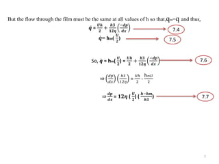
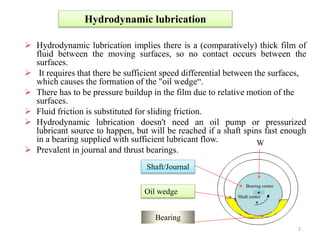
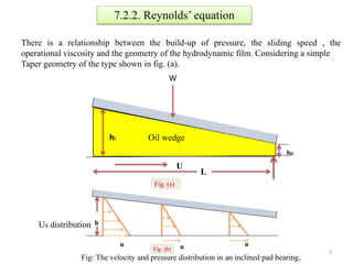
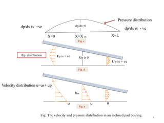
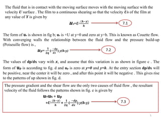
Presented By : BASHAR MD KHAIRUL
Student ID:15595901
Masters Student
Graduate School of Science & Engineering
Saga University
1
Advanced Lubrication Engineering
Hydrodynamic lubrication
(Friday January 22, 2016 @ multipurpose lecture room)
Hydrodynamic lubrication
 Hydrodynamic lubrication implies there is a (comparatively) thick film of
fluid between the moving surfaces, so no contact occurs between the
surfaces.
 It requires that there be sufficient speed differential between the surfaces,
which causes the formation of the "oil wedge“.
 There has to be pressure buildup in the film due to relative motion of the
surfaces.
 Fluid friction is substituted for sliding friction.
 Hydrodynamic lubrication doesn't need an oil pump or pressurized
lubricant source to happen, but will be reached if a shaft spins fast enough
in a bearing supplied with sufficient lubricant flow.
 Prevalent in journal and thrust bearings.
Shaft/Journal
Oil wedge
Bearing
+
W
Bearing center
+
Shaft center
2
7.2.2. Reynolds’ equation
There is a relationship between the build-up of pressure, the sliding speed , the
operational viscosity and the geometry of the hydrodynamic film. Considering a simple
Taper geometry of the type shown in fig. (a).
Oil wedge
W
hi
ho
U
L
h
u
Fig. (a)
u u
Fig. (b)
Us distribution
Fig: The velocity and pressure distribution in an inclined pad bearing.
3
Fig. c
X=0 X=X m X=L
dp/dx is +ve dp/dx is - ve
dp/dx=0
Pressure distribution
Up is + ve
Up is + ve Up is 0
Up distribution
Fig. d
u
hm
uu
Fig. e
Velocity distribution u=us+ up
Fig: The velocity and pressure distribution in an inclined pad bearing.
4
The fluid that is in contact with the moving surface moves with the moving surface with the
velocity U surface . The film to a continuous shearing so that the velocity Us of the film at
any value of Y is given by
us=U
(𝒉−𝒚)
𝒉
The form of us is shown in fig b; us is +U at y=0 and zero at y=h. This is known as Couette flow.
With converging walls the relationship between the fluid flow and the pressure build-up
(Poiseuille flow) is ,
up=
𝟏
𝟐𝜼
(
−𝒅𝒑
𝒅𝒙
) y(h-y)
7.1
The values of dp/dx vary with x, and assume that this variation is as shown in figure c . The
form of up is according to fig. d and up is zero at y=0 and y=h. At the entry section dp/dx will
be positive, near the center it will be zero , and after this point it will be negative . This gives rise
to the patterns of up shown in fig. d.
The pressure gradient and the shear flow are the only two causes of fluid flow , the resultant
velocity of the fluid follows the patterns shown in fig. e is given by
u=us + up
=U
(𝒉−𝒚)
𝒉
+
𝟏
𝟐𝜼
(
−𝒅𝒑
𝒅𝒙
) y(h-y)
7.1
7.2
7.3
5
Neglecting any side flow , the area of an element of film is 1×dy per unit width of the film. The
quantity flowing per unit time is thus u dy for each element area and the total flow q is given by
q= 𝟎
𝒉
𝒖 𝒅𝒚
Substituting for u from equation (7.3) and integrating
𝑞 = 0
ℎ
𝑈.
ℎ−𝑦
ℎ
𝑑𝑦 + 0
ℎ 1
2𝜂
−𝑑𝑝
𝑑𝑥
𝑦ℎ −
1
2𝜂
−𝑑𝑝
𝑑𝑥
𝑦2 𝑑𝑦
𝒒=
𝑼𝒉
𝟐
+
𝒉𝟑
𝟏𝟐𝜼
−𝒅𝒑
𝒅𝒙
.
7.4
At some point the pressure is maximum and
𝒅𝒑
𝒅𝒙
=0; let the value of h at this point be hm
(maximum) whence, 𝑞=
𝑈ℎ
2
+
ℎ3
12𝜂
−𝑑𝑝
𝑑𝑥
=0 [As some point the pressure is maximum;
𝒅𝒑
𝒅𝒙
=0]
𝑞=h(
𝑈
2
) [note: let the value of h at this point be hm]
qm=hm(
𝑼
𝟐
)
.
7.5
.
6
.
So,
But the flow through the film must be the same at all values of h so that,qm=q and thus,
𝒒 =
𝑼𝒉
𝟐
+
𝒉𝟑
𝟏𝟐𝜼
−𝒅𝒑
𝒅𝒙
𝒒= hm(
𝑼
𝟐
)
So, 𝒒 = hm(
𝑼
𝟐
) =
𝑼𝒉
𝟐
+
𝒉𝟑
𝟏𝟐𝜼
−𝒅𝒑
𝒅𝒙
2 𝑑𝑝
𝑑𝑥
ℎ3
12𝜂
=
𝑈ℎ
2
-
hm 𝑈
2
𝟐 𝒅𝒑
𝒅𝒙
= 𝟏𝟐𝜼 (
𝑼
𝟐
) (
𝒉−𝒉𝒎
𝒉𝟑
)
7.4
7.5
7.6
7.7
7
どうもありがとうございます.
Thank you very much.
8

Hydrodynamic lubrication By Khairul Bashar

  • 1.
    Presented By :BASHAR MD KHAIRUL Student ID:15595901 Masters Student Graduate School of Science & Engineering Saga University 1 Advanced Lubrication Engineering Hydrodynamic lubrication (Friday January 22, 2016 @ multipurpose lecture room)
  • 2.
    Hydrodynamic lubrication  Hydrodynamiclubrication implies there is a (comparatively) thick film of fluid between the moving surfaces, so no contact occurs between the surfaces.  It requires that there be sufficient speed differential between the surfaces, which causes the formation of the "oil wedge“.  There has to be pressure buildup in the film due to relative motion of the surfaces.  Fluid friction is substituted for sliding friction.  Hydrodynamic lubrication doesn't need an oil pump or pressurized lubricant source to happen, but will be reached if a shaft spins fast enough in a bearing supplied with sufficient lubricant flow.  Prevalent in journal and thrust bearings. Shaft/Journal Oil wedge Bearing + W Bearing center + Shaft center 2
  • 3.
    7.2.2. Reynolds’ equation Thereis a relationship between the build-up of pressure, the sliding speed , the operational viscosity and the geometry of the hydrodynamic film. Considering a simple Taper geometry of the type shown in fig. (a). Oil wedge W hi ho U L h u Fig. (a) u u Fig. (b) Us distribution Fig: The velocity and pressure distribution in an inclined pad bearing. 3
  • 4.
    Fig. c X=0 X=Xm X=L dp/dx is +ve dp/dx is - ve dp/dx=0 Pressure distribution Up is + ve Up is + ve Up is 0 Up distribution Fig. d u hm uu Fig. e Velocity distribution u=us+ up Fig: The velocity and pressure distribution in an inclined pad bearing. 4
  • 5.
    The fluid thatis in contact with the moving surface moves with the moving surface with the velocity U surface . The film to a continuous shearing so that the velocity Us of the film at any value of Y is given by us=U (𝒉−𝒚) 𝒉 The form of us is shown in fig b; us is +U at y=0 and zero at y=h. This is known as Couette flow. With converging walls the relationship between the fluid flow and the pressure build-up (Poiseuille flow) is , up= 𝟏 𝟐𝜼 ( −𝒅𝒑 𝒅𝒙 ) y(h-y) 7.1 The values of dp/dx vary with x, and assume that this variation is as shown in figure c . The form of up is according to fig. d and up is zero at y=0 and y=h. At the entry section dp/dx will be positive, near the center it will be zero , and after this point it will be negative . This gives rise to the patterns of up shown in fig. d. The pressure gradient and the shear flow are the only two causes of fluid flow , the resultant velocity of the fluid follows the patterns shown in fig. e is given by u=us + up =U (𝒉−𝒚) 𝒉 + 𝟏 𝟐𝜼 ( −𝒅𝒑 𝒅𝒙 ) y(h-y) 7.1 7.2 7.3 5
  • 6.
    Neglecting any sideflow , the area of an element of film is 1×dy per unit width of the film. The quantity flowing per unit time is thus u dy for each element area and the total flow q is given by q= 𝟎 𝒉 𝒖 𝒅𝒚 Substituting for u from equation (7.3) and integrating 𝑞 = 0 ℎ 𝑈. ℎ−𝑦 ℎ 𝑑𝑦 + 0 ℎ 1 2𝜂 −𝑑𝑝 𝑑𝑥 𝑦ℎ − 1 2𝜂 −𝑑𝑝 𝑑𝑥 𝑦2 𝑑𝑦 𝒒= 𝑼𝒉 𝟐 + 𝒉𝟑 𝟏𝟐𝜼 −𝒅𝒑 𝒅𝒙 . 7.4 At some point the pressure is maximum and 𝒅𝒑 𝒅𝒙 =0; let the value of h at this point be hm (maximum) whence, 𝑞= 𝑈ℎ 2 + ℎ3 12𝜂 −𝑑𝑝 𝑑𝑥 =0 [As some point the pressure is maximum; 𝒅𝒑 𝒅𝒙 =0] 𝑞=h( 𝑈 2 ) [note: let the value of h at this point be hm] qm=hm( 𝑼 𝟐 ) . 7.5 . 6 . So,
  • 7.
    But the flowthrough the film must be the same at all values of h so that,qm=q and thus, 𝒒 = 𝑼𝒉 𝟐 + 𝒉𝟑 𝟏𝟐𝜼 −𝒅𝒑 𝒅𝒙 𝒒= hm( 𝑼 𝟐 ) So, 𝒒 = hm( 𝑼 𝟐 ) = 𝑼𝒉 𝟐 + 𝒉𝟑 𝟏𝟐𝜼 −𝒅𝒑 𝒅𝒙 2 𝑑𝑝 𝑑𝑥 ℎ3 12𝜂 = 𝑈ℎ 2 - hm 𝑈 2 𝟐 𝒅𝒑 𝒅𝒙 = 𝟏𝟐𝜼 ( 𝑼 𝟐 ) ( 𝒉−𝒉𝒎 𝒉𝟑 ) 7.4 7.5 7.6 7.7 7
  • 8.