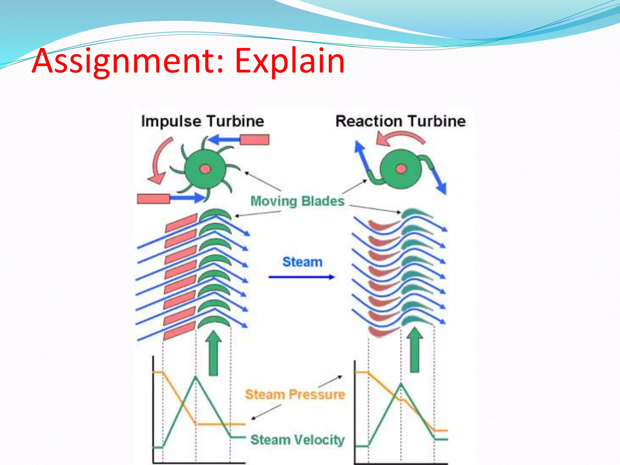
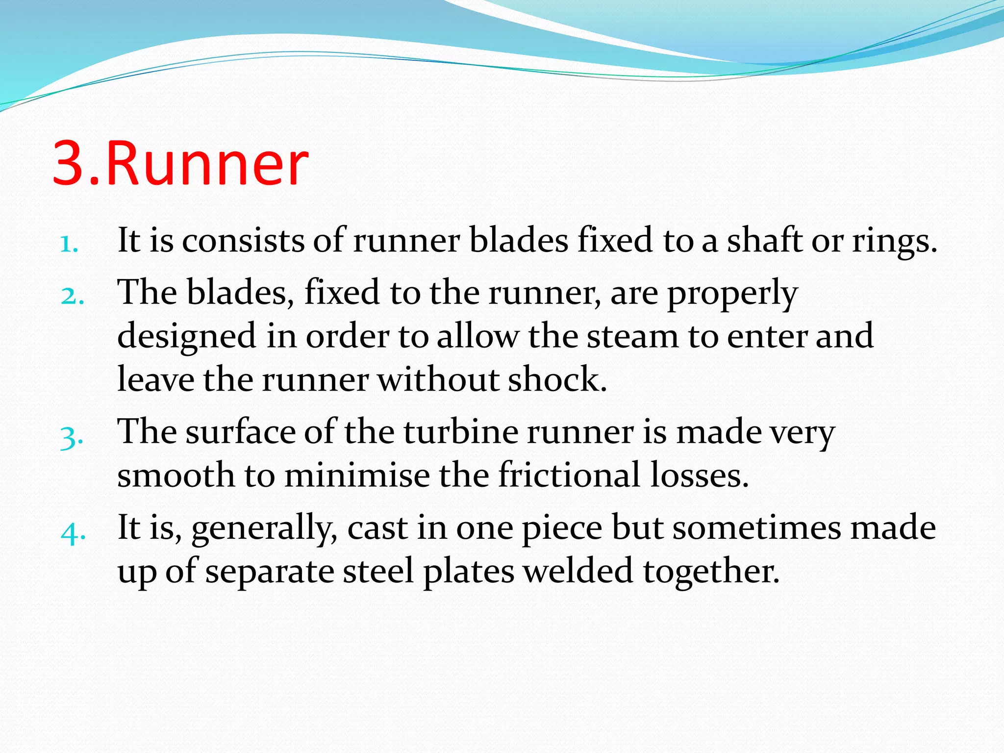
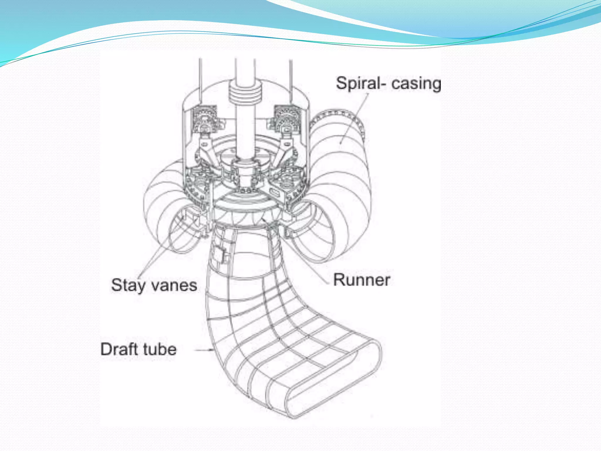
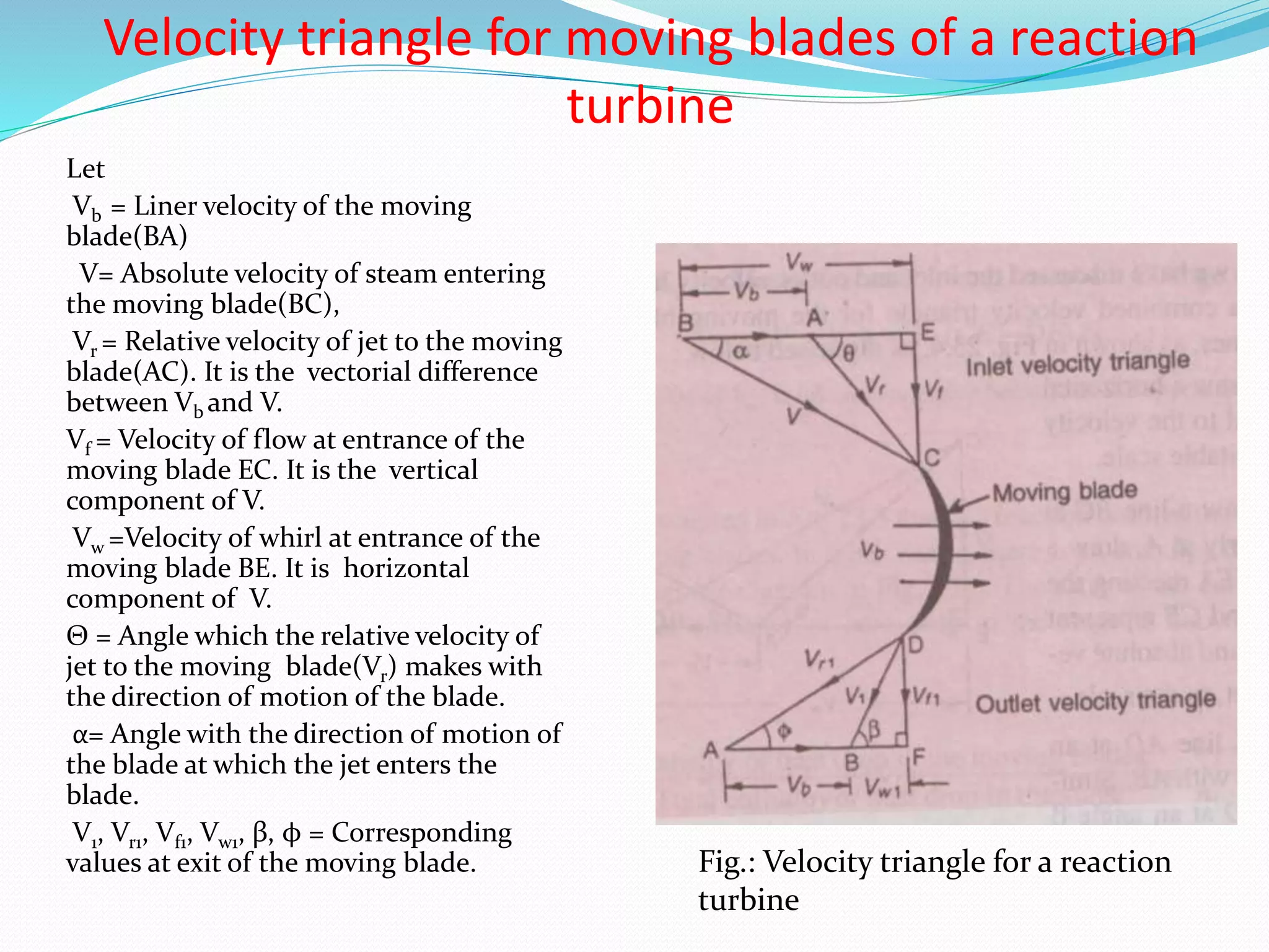
Impulse turbines use steam jets to transfer momentum to rotating blades, while reaction turbines use the pressure of steam flowing over stationary and moving blades to rotate the shaft. Both use velocity triangles to analyze steam flow at the inlet and outlet of curved blades. The power produced depends on the change in steam whirl velocity as it flows through the blades. Reaction turbines experience axial thrust from the change in steam flow velocity from inlet to outlet.

![Power produced by an Impulse
Turbine
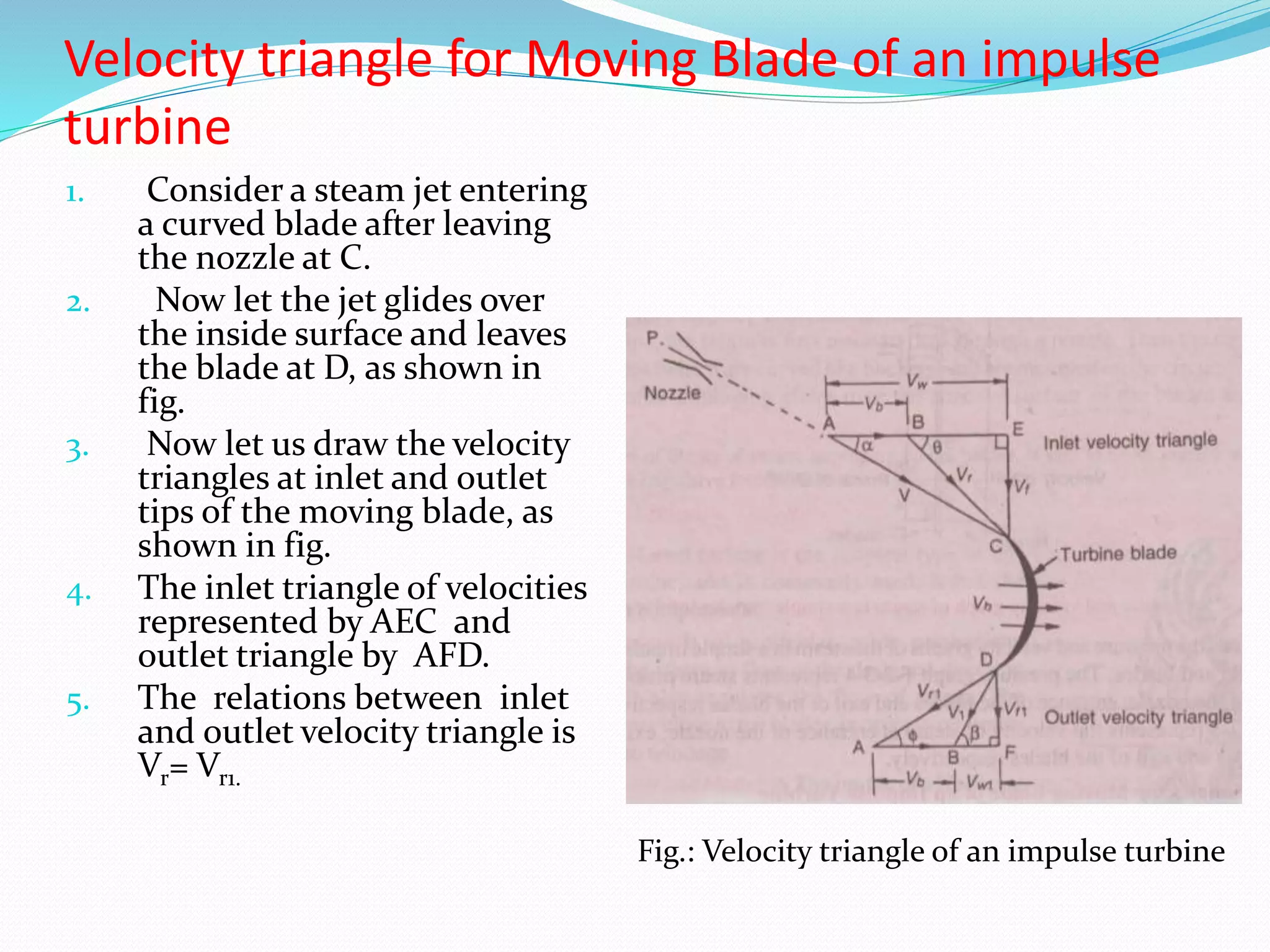
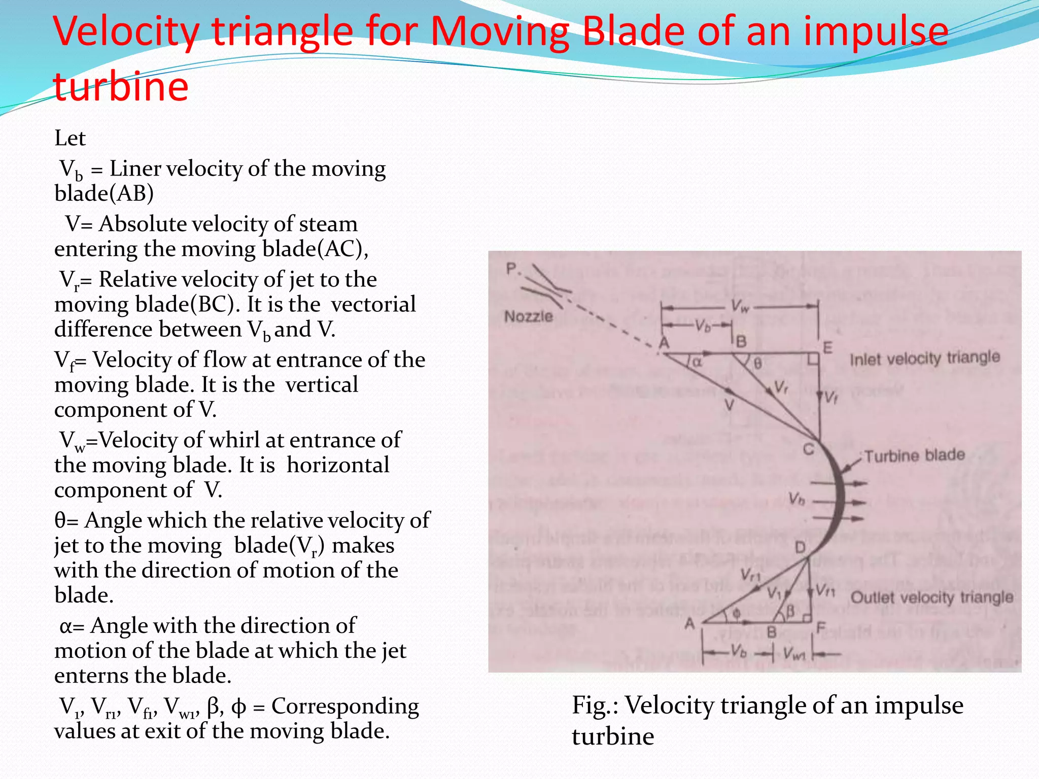
Consider an impulse turbine working under the action of a steam jet.
Let,
m = Mass of steam flowing through the turbine in Kg./s
Now, Change in the velocity of whirl in m/s = Vw+ Vw1 [Vw – (– Vw1 ), when Vw1 is
negative]
We know that according to the Newton’s second law of motion, force in the
direction of motion of the blades
Fx = Mass of steam flowing per second × Change in the velocity of whirl
= m(Vw+ Vw1)
and work done in the direction of motion of the blades
= Force × distance
= m(Vw+ Vw1)× Vb N-m/s
So,
Power produced by the turbine P= m(Vw+ Vw1)× Vb watts. [ 1 N-m/s = 1 watt]](https://image.slidesharecdn.com/7thlecture-180118093940/75/Velocity-Triangle-for-Moving-Blade-of-an-impulse-Turbine-4-2048.jpg)
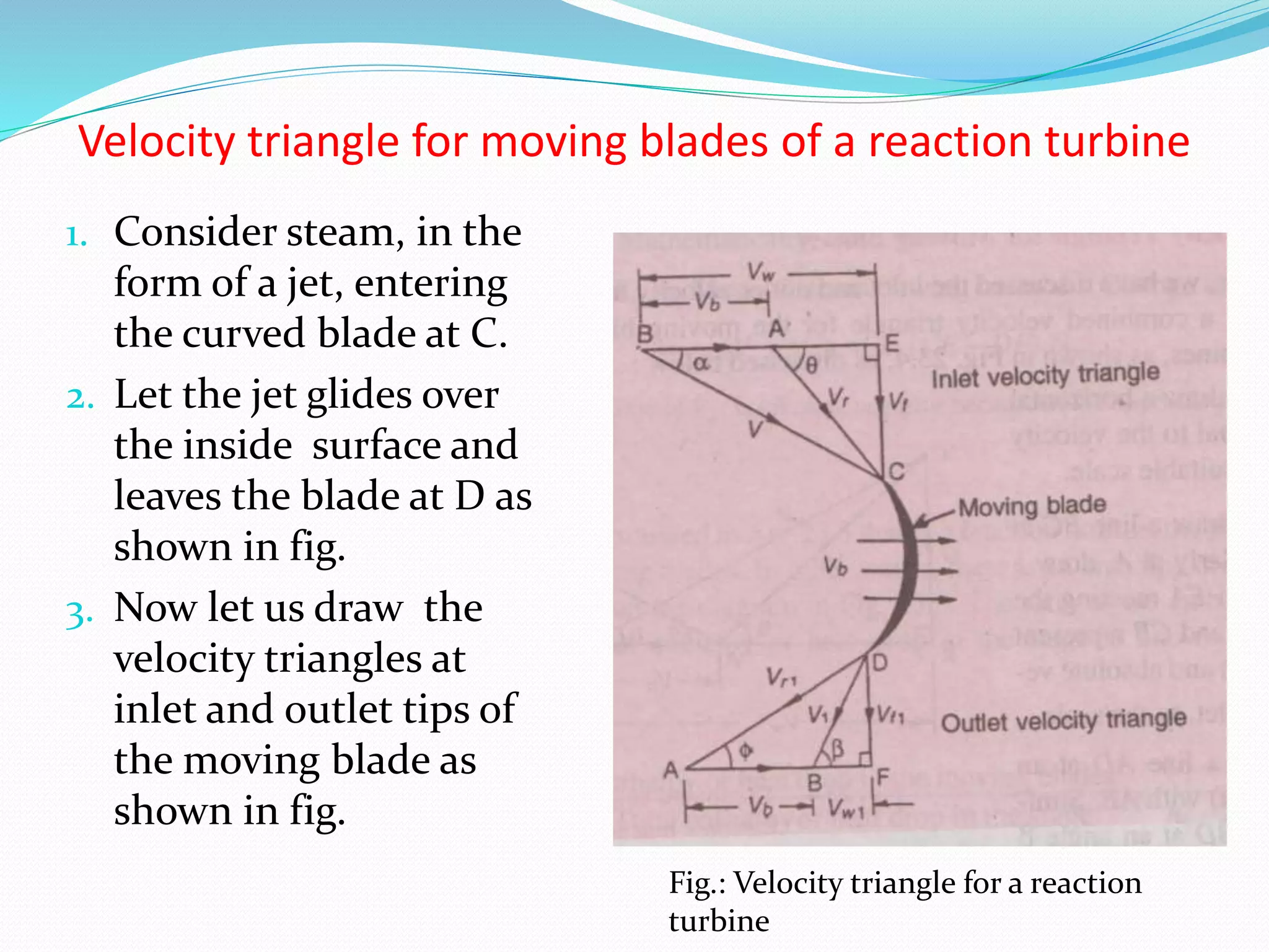
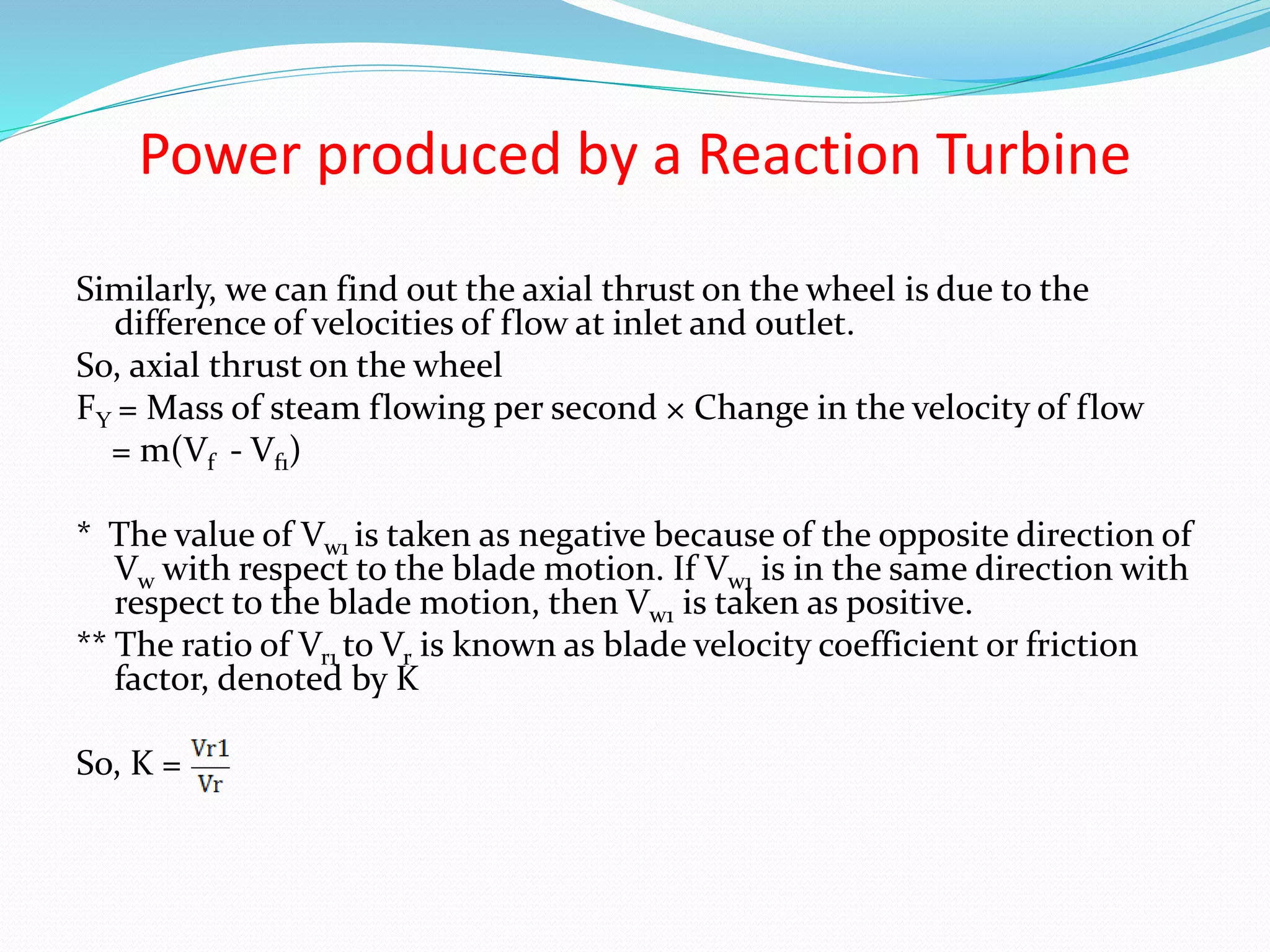
![Power produced by a Reaction Turbine
Consider a reaction turbine working under the action of a steam jet.
Let,
m= Mass of steam flowing through the turbine in Kg./s,
Change in the velocity of whirl in m/s = Vw+ Vw1 [Vw – (– Vw1 ), when Vw1 is
negative]
We know that according to the Newton’s second law of motion, force in the
direction of motion of the blades
Fx = Mass of steam flowing per second × Change in the velocity of whirl
= m(Vw+ Vw1)
and work done in the direction of motion of the blades
= Force × distance
= m(Vw+ Vw1)× Vb N-m/s
So,
Power produced by the turbine P= m(Vw+ Vw1)× Vb watts. [ 1 N-m/s = 1 watt]](https://image.slidesharecdn.com/7thlecture-180118093940/75/Velocity-Triangle-for-Moving-Blade-of-an-impulse-Turbine-14-2048.jpg)