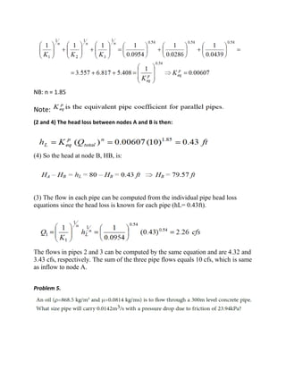
SlideShare a Scribd company logo
1 of 8
Download to read offline
A series of pipes may have different pipe diameters and/or roughness parameters. The total head
loss is equal to the sum of the head loss in each pipe segment
u
Hydraulics (CEC 301)
Lecture 2
Ramat
Polytechnic
Energy Loss in Non-Circular Pipes
Problem 2
For a flow rate of 0.04m3
/s determine the pressure and total heads at points A, B, C, and D for
series pipes shown in Figure below. Assume fully turbulent flow for all cases and the pressure
head at point A is 40m.
Fig. 2.1: Pipes in series with data
Solution
The pressure and total heads are computed using the energy equation along the path beginning at
point A. Given the pressure head and elevation, the total head at point A is:
Note the velocity and velocity head are:
The velocity head is four orders of magnitude less than the static head so it can be neglected.
Neglecting velocity head is a common assumption in pipe network analysis. All energy loss in
the system is due to friction. So following the path of flow the total heads at A, B, C, and D are:
Problem 3.
For the series pipe system in figure 2.1, find the equivalent roughness coefficient and the total
head at point D for a flow rate of 0.03 m3
/s.
Solution
The equivalent pipe loss coefficient is equal to the sum of the pipe coefficients or:
Note: An equivalent pipe is a pipe of uniform diameter having loss of equal head and discharge
of compound pipes of different lengths and diameters.
For this problem:
Note that pipe 2 has the largest loss coefficient since it has the smallest diameter and
highest flow velocity. As seen in Example 5.1, although it has the shortest length, most of
the head loss occurs in this section. The head loss between nodes A and D for Q = 0.03
m3
/s is then:
Considering the figure below:
The relationship that must hold is that the head loss in pipes 1, 2, and 3 must be the same.
Since all begin at a single node (A) and all end at a single node (B) and the difference in
head between those two nodes is unique, regardless of the pipe characteristics the head
loss in the pipes is the same or
Fig. 2.3: Pipes in parallel with data
Problem 4
Given the data for the three parallel pipes in Figure 2.3 above, compute:
(1) the equivalent parallel pipe coefficient,
(2) the head loss between nodes A and B,
(3) the flow rates in each pipe, and
(4) the total head at node B
Solution
The equivalent parallel pipe coefficient allows us to determine the head loss that can then
be used to disaggregate the flow between pipes. The loss coefficient for the Hazen
Williams equation for pipe 1 with English units is:
Similarly, K2
and K3
equal to 0.0286 and 0.0439, respectively. The equivalent loss
coefficient is:
NB: n = 1.85
Note:
(2 and 4) The head loss between nodes A and B is then:
(4) So the head at node B, HB, is:
(3) The flow in each pipe can be computed from the individual pipe head loss
equations since the head loss is known for each pipe (hL= 0.43ft).
The flows in pipes 2 and 3 can be computed by the same equation and are 4.32 and
3.43 cfs, respectively. The sum of the three pipe flows equals 10 cfs, which is same
as inflow to node A.
Problem 5.
Solution
Hydraulics lecture note

More Related Content

What's hot

Fluid MechanicsLosses in pipes dynamics of viscous flows
Fluid MechanicsLosses in pipes dynamics of viscous flowsFluid MechanicsLosses in pipes dynamics of viscous flows
Fluid MechanicsLosses in pipes dynamics of viscous flows
Mohsin Siddique
 

What's hot (20)

Flow through pipes
Flow through pipesFlow through pipes
Flow through pipes
 
Canal irrigation
Canal irrigationCanal irrigation
Canal irrigation
 
Numerical problem and solution on pile capacity (usefulsearch.org) ( usefuls...
Numerical problem and solution on pile capacity (usefulsearch.org) ( usefuls...Numerical problem and solution on pile capacity (usefulsearch.org) ( usefuls...
Numerical problem and solution on pile capacity (usefulsearch.org) ( usefuls...
 
Chapter 8 hydraulic jump
Chapter 8 hydraulic jumpChapter 8 hydraulic jump
Chapter 8 hydraulic jump
 
Unit hydrograph
Unit hydrographUnit hydrograph
Unit hydrograph
 
Unit4 kvv
Unit4 kvvUnit4 kvv
Unit4 kvv
 
Weirs
WeirsWeirs
Weirs
 
Chapter 2 open channel hydraulics
Chapter 2 open channel hydraulicsChapter 2 open channel hydraulics
Chapter 2 open channel hydraulics
 
(Part i)- open channels
(Part i)- open channels(Part i)- open channels
(Part i)- open channels
 
Chapter 4 seepage theories
Chapter 4 seepage theoriesChapter 4 seepage theories
Chapter 4 seepage theories
 
Irrigation Channels
Irrigation ChannelsIrrigation Channels
Irrigation Channels
 
Presentation on notches and weirs
Presentation on notches and weirsPresentation on notches and weirs
Presentation on notches and weirs
 
Types of flow in open channel
Types of flow in open channelTypes of flow in open channel
Types of flow in open channel
 
Hydraulic jump
Hydraulic jumpHydraulic jump
Hydraulic jump
 
Fluid MechanicsLosses in pipes dynamics of viscous flows
Fluid MechanicsLosses in pipes dynamics of viscous flowsFluid MechanicsLosses in pipes dynamics of viscous flows
Fluid MechanicsLosses in pipes dynamics of viscous flows
 
Stilling basin
Stilling basinStilling basin
Stilling basin
 
Fm gtu hydrostatics static forces on surface ppt
Fm gtu hydrostatics static forces on surface pptFm gtu hydrostatics static forces on surface ppt
Fm gtu hydrostatics static forces on surface ppt
 
Weirs on Permeable Foundations
Weirs on Permeable FoundationsWeirs on Permeable Foundations
Weirs on Permeable Foundations
 
Gravity dam stability analysis
Gravity dam stability analysisGravity dam stability analysis
Gravity dam stability analysis
 
Open channelhydraulics2
Open channelhydraulics2Open channelhydraulics2
Open channelhydraulics2
 

Similar to Hydraulics lecture note

Exploring the Use of Computation Fluid Dynamics to Model a T-Junction for UM ...
Exploring the Use of Computation Fluid Dynamics to Model a T-Junction for UM ...Exploring the Use of Computation Fluid Dynamics to Model a T-Junction for UM ...
Exploring the Use of Computation Fluid Dynamics to Model a T-Junction for UM ...
Doug Kripke
 
Answers assignment 3 integral methods-fluid mechanics
Answers assignment 3 integral methods-fluid mechanicsAnswers assignment 3 integral methods-fluid mechanics
Answers assignment 3 integral methods-fluid mechanics
asghar123456
 

Similar to Hydraulics lecture note (20)

Solved problems pipe flow final 1.doc
Solved problems pipe flow final 1.docSolved problems pipe flow final 1.doc
Solved problems pipe flow final 1.doc
 
pipe lines lec 2.pptx
pipe lines lec 2.pptxpipe lines lec 2.pptx
pipe lines lec 2.pptx
 
pipe lines lec 5.pdf
pipe lines lec 5.pdfpipe lines lec 5.pdf
pipe lines lec 5.pdf
 
Pipeline Design Project
Pipeline Design ProjectPipeline Design Project
Pipeline Design Project
 
pipe lines lec 2.pptx
pipe lines lec 2.pptxpipe lines lec 2.pptx
pipe lines lec 2.pptx
 
Water and waste water oep
Water and waste water oep Water and waste water oep
Water and waste water oep
 
Fluid Mech. Presentation 2nd year B.Tech.
Fluid Mech. Presentation 2nd year B.Tech.Fluid Mech. Presentation 2nd year B.Tech.
Fluid Mech. Presentation 2nd year B.Tech.
 
pipe lines lec 4.pptx
pipe lines lec 4.pptxpipe lines lec 4.pptx
pipe lines lec 4.pptx
 
S3 Minor Losses Presentation
S3 Minor Losses PresentationS3 Minor Losses Presentation
S3 Minor Losses Presentation
 
008
008008
008
 
Exploring the Use of Computation Fluid Dynamics to Model a T-Junction for UM ...
Exploring the Use of Computation Fluid Dynamics to Model a T-Junction for UM ...Exploring the Use of Computation Fluid Dynamics to Model a T-Junction for UM ...
Exploring the Use of Computation Fluid Dynamics to Model a T-Junction for UM ...
 
Answers assignment 3 integral methods-fluid mechanics
Answers assignment 3 integral methods-fluid mechanicsAnswers assignment 3 integral methods-fluid mechanics
Answers assignment 3 integral methods-fluid mechanics
 
Flow In Pipes
Flow In PipesFlow In Pipes
Flow In Pipes
 
Hydraulic Engineering Assignment Help
Hydraulic Engineering Assignment HelpHydraulic Engineering Assignment Help
Hydraulic Engineering Assignment Help
 
PROBLEMA 3
PROBLEMA 3 PROBLEMA 3
PROBLEMA 3
 
A109212102 mechanicsoffluids1
A109212102 mechanicsoffluids1A109212102 mechanicsoffluids1
A109212102 mechanicsoffluids1
 
Ejercicio 1. Ecuación Darcy W.
Ejercicio 1. Ecuación Darcy W.Ejercicio 1. Ecuación Darcy W.
Ejercicio 1. Ecuación Darcy W.
 
Unit6 energy loss in pipelines
Unit6   energy loss in pipelinesUnit6   energy loss in pipelines
Unit6 energy loss in pipelines
 
Source models
Source modelsSource models
Source models
 
Flow through pipes ppt
Flow through pipes pptFlow through pipes ppt
Flow through pipes ppt
 

Recently uploaded

Cara Menggugurkan Sperma Yang Masuk Rahim Biyar Tidak Hamil
Cara Menggugurkan Sperma Yang Masuk Rahim Biyar Tidak HamilCara Menggugurkan Sperma Yang Masuk Rahim Biyar Tidak Hamil
Cara Menggugurkan Sperma Yang Masuk Rahim Biyar Tidak Hamil
Cara Menggugurkan Kandungan 087776558899
 
Call Girls in South Ex (delhi) call me [🔝9953056974🔝] escort service 24X7
Call Girls in South Ex (delhi) call me [🔝9953056974🔝] escort service 24X7Call Girls in South Ex (delhi) call me [🔝9953056974🔝] escort service 24X7
Call Girls in South Ex (delhi) call me [🔝9953056974🔝] escort service 24X7
9953056974 Low Rate Call Girls In Saket, Delhi NCR
 
notes on Evolution Of Analytic Scalability.ppt
notes on Evolution Of Analytic Scalability.pptnotes on Evolution Of Analytic Scalability.ppt
notes on Evolution Of Analytic Scalability.ppt
MsecMca
 
Kuwait City MTP kit ((+919101817206)) Buy Abortion Pills Kuwait
Kuwait City MTP kit ((+919101817206)) Buy Abortion Pills KuwaitKuwait City MTP kit ((+919101817206)) Buy Abortion Pills Kuwait
Kuwait City MTP kit ((+919101817206)) Buy Abortion Pills Kuwait
jaanualu31
 
Integrated Test Rig For HTFE-25 - Neometrix
Integrated Test Rig For HTFE-25 - NeometrixIntegrated Test Rig For HTFE-25 - Neometrix
Integrated Test Rig For HTFE-25 - Neometrix
Neometrix_Engineering_Pvt_Ltd
 

Recently uploaded (20)

Unleashing the Power of the SORA AI lastest leap
Unleashing the Power of the SORA AI lastest leapUnleashing the Power of the SORA AI lastest leap
Unleashing the Power of the SORA AI lastest leap
 
Minimum and Maximum Modes of microprocessor 8086
Minimum and Maximum Modes of microprocessor 8086Minimum and Maximum Modes of microprocessor 8086
Minimum and Maximum Modes of microprocessor 8086
 
Cara Menggugurkan Sperma Yang Masuk Rahim Biyar Tidak Hamil
Cara Menggugurkan Sperma Yang Masuk Rahim Biyar Tidak HamilCara Menggugurkan Sperma Yang Masuk Rahim Biyar Tidak Hamil
Cara Menggugurkan Sperma Yang Masuk Rahim Biyar Tidak Hamil
 
HOA1&2 - Module 3 - PREHISTORCI ARCHITECTURE OF KERALA.pptx
HOA1&2 - Module 3 - PREHISTORCI ARCHITECTURE OF KERALA.pptxHOA1&2 - Module 3 - PREHISTORCI ARCHITECTURE OF KERALA.pptx
HOA1&2 - Module 3 - PREHISTORCI ARCHITECTURE OF KERALA.pptx
 
Call Girls in South Ex (delhi) call me [🔝9953056974🔝] escort service 24X7
Call Girls in South Ex (delhi) call me [🔝9953056974🔝] escort service 24X7Call Girls in South Ex (delhi) call me [🔝9953056974🔝] escort service 24X7
Call Girls in South Ex (delhi) call me [🔝9953056974🔝] escort service 24X7
 
kiln thermal load.pptx kiln tgermal load
kiln thermal load.pptx kiln tgermal loadkiln thermal load.pptx kiln tgermal load
kiln thermal load.pptx kiln tgermal load
 
Thermal Engineering Unit - I & II . ppt
Thermal Engineering  Unit - I & II . pptThermal Engineering  Unit - I & II . ppt
Thermal Engineering Unit - I & II . ppt
 
Thermal Engineering-R & A / C - unit - V
Thermal Engineering-R & A / C - unit - VThermal Engineering-R & A / C - unit - V
Thermal Engineering-R & A / C - unit - V
 
A CASE STUDY ON CERAMIC INDUSTRY OF BANGLADESH.pptx
A CASE STUDY ON CERAMIC INDUSTRY OF BANGLADESH.pptxA CASE STUDY ON CERAMIC INDUSTRY OF BANGLADESH.pptx
A CASE STUDY ON CERAMIC INDUSTRY OF BANGLADESH.pptx
 
Bridge Jacking Design Sample Calculation.pptx
Bridge Jacking Design Sample Calculation.pptxBridge Jacking Design Sample Calculation.pptx
Bridge Jacking Design Sample Calculation.pptx
 
notes on Evolution Of Analytic Scalability.ppt
notes on Evolution Of Analytic Scalability.pptnotes on Evolution Of Analytic Scalability.ppt
notes on Evolution Of Analytic Scalability.ppt
 
Navigating Complexity: The Role of Trusted Partners and VIAS3D in Dassault Sy...
Navigating Complexity: The Role of Trusted Partners and VIAS3D in Dassault Sy...Navigating Complexity: The Role of Trusted Partners and VIAS3D in Dassault Sy...
Navigating Complexity: The Role of Trusted Partners and VIAS3D in Dassault Sy...
 
Rums floating Omkareshwar FSPV IM_16112021.pdf
Rums floating Omkareshwar FSPV IM_16112021.pdfRums floating Omkareshwar FSPV IM_16112021.pdf
Rums floating Omkareshwar FSPV IM_16112021.pdf
 
Kuwait City MTP kit ((+919101817206)) Buy Abortion Pills Kuwait
Kuwait City MTP kit ((+919101817206)) Buy Abortion Pills KuwaitKuwait City MTP kit ((+919101817206)) Buy Abortion Pills Kuwait
Kuwait City MTP kit ((+919101817206)) Buy Abortion Pills Kuwait
 
Integrated Test Rig For HTFE-25 - Neometrix
Integrated Test Rig For HTFE-25 - NeometrixIntegrated Test Rig For HTFE-25 - Neometrix
Integrated Test Rig For HTFE-25 - Neometrix
 
DC MACHINE-Motoring and generation, Armature circuit equation
DC MACHINE-Motoring and generation, Armature circuit equationDC MACHINE-Motoring and generation, Armature circuit equation
DC MACHINE-Motoring and generation, Armature circuit equation
 
Employee leave management system project.
Employee leave management system project.Employee leave management system project.
Employee leave management system project.
 
Hostel management system project report..pdf
Hostel management system project report..pdfHostel management system project report..pdf
Hostel management system project report..pdf
 
Computer Lecture 01.pptxIntroduction to Computers
Computer Lecture 01.pptxIntroduction to ComputersComputer Lecture 01.pptxIntroduction to Computers
Computer Lecture 01.pptxIntroduction to Computers
 
Online electricity billing project report..pdf
Online electricity billing project report..pdfOnline electricity billing project report..pdf
Online electricity billing project report..pdf
 

Hydraulics lecture note

  • 1. A series of pipes may have different pipe diameters and/or roughness parameters. The total head loss is equal to the sum of the head loss in each pipe segment u Hydraulics (CEC 301) Lecture 2 Ramat Polytechnic
  • 2. Energy Loss in Non-Circular Pipes Problem 2 For a flow rate of 0.04m3 /s determine the pressure and total heads at points A, B, C, and D for series pipes shown in Figure below. Assume fully turbulent flow for all cases and the pressure head at point A is 40m. Fig. 2.1: Pipes in series with data
  • 3. Solution The pressure and total heads are computed using the energy equation along the path beginning at point A. Given the pressure head and elevation, the total head at point A is: Note the velocity and velocity head are: The velocity head is four orders of magnitude less than the static head so it can be neglected. Neglecting velocity head is a common assumption in pipe network analysis. All energy loss in the system is due to friction. So following the path of flow the total heads at A, B, C, and D are:
  • 4. Problem 3. For the series pipe system in figure 2.1, find the equivalent roughness coefficient and the total head at point D for a flow rate of 0.03 m3 /s. Solution The equivalent pipe loss coefficient is equal to the sum of the pipe coefficients or: Note: An equivalent pipe is a pipe of uniform diameter having loss of equal head and discharge of compound pipes of different lengths and diameters. For this problem: Note that pipe 2 has the largest loss coefficient since it has the smallest diameter and highest flow velocity. As seen in Example 5.1, although it has the shortest length, most of the head loss occurs in this section. The head loss between nodes A and D for Q = 0.03 m3 /s is then:
  • 5. Considering the figure below: The relationship that must hold is that the head loss in pipes 1, 2, and 3 must be the same. Since all begin at a single node (A) and all end at a single node (B) and the difference in head between those two nodes is unique, regardless of the pipe characteristics the head loss in the pipes is the same or Fig. 2.3: Pipes in parallel with data Problem 4 Given the data for the three parallel pipes in Figure 2.3 above, compute: (1) the equivalent parallel pipe coefficient, (2) the head loss between nodes A and B, (3) the flow rates in each pipe, and (4) the total head at node B Solution The equivalent parallel pipe coefficient allows us to determine the head loss that can then be used to disaggregate the flow between pipes. The loss coefficient for the Hazen Williams equation for pipe 1 with English units is: Similarly, K2 and K3 equal to 0.0286 and 0.0439, respectively. The equivalent loss coefficient is:
  • 6. NB: n = 1.85 Note: (2 and 4) The head loss between nodes A and B is then: (4) So the head at node B, HB, is: (3) The flow in each pipe can be computed from the individual pipe head loss equations since the head loss is known for each pipe (hL= 0.43ft). The flows in pipes 2 and 3 can be computed by the same equation and are 4.32 and 3.43 cfs, respectively. The sum of the three pipe flows equals 10 cfs, which is same as inflow to node A. Problem 5.