Downloaded 126 times

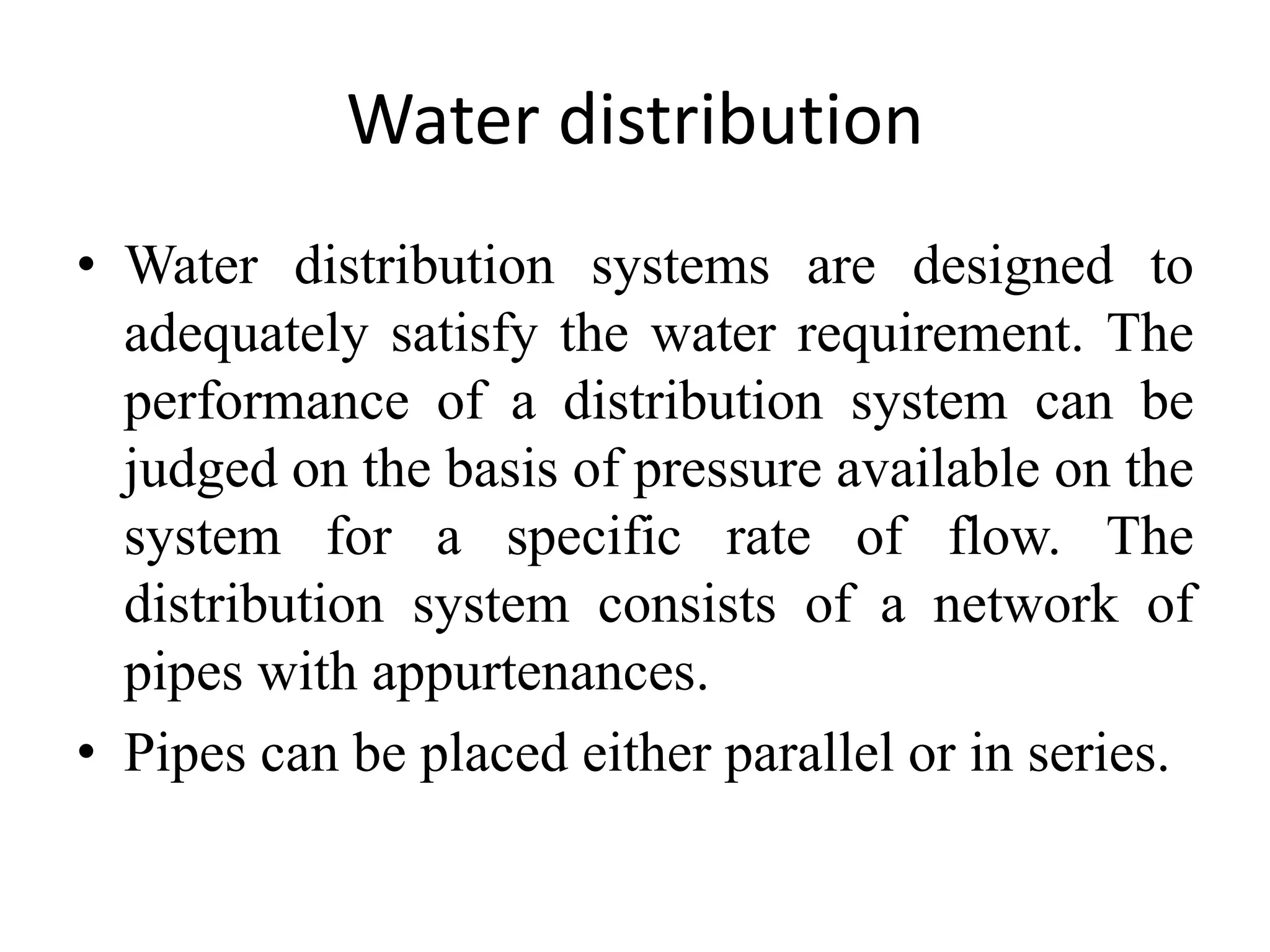
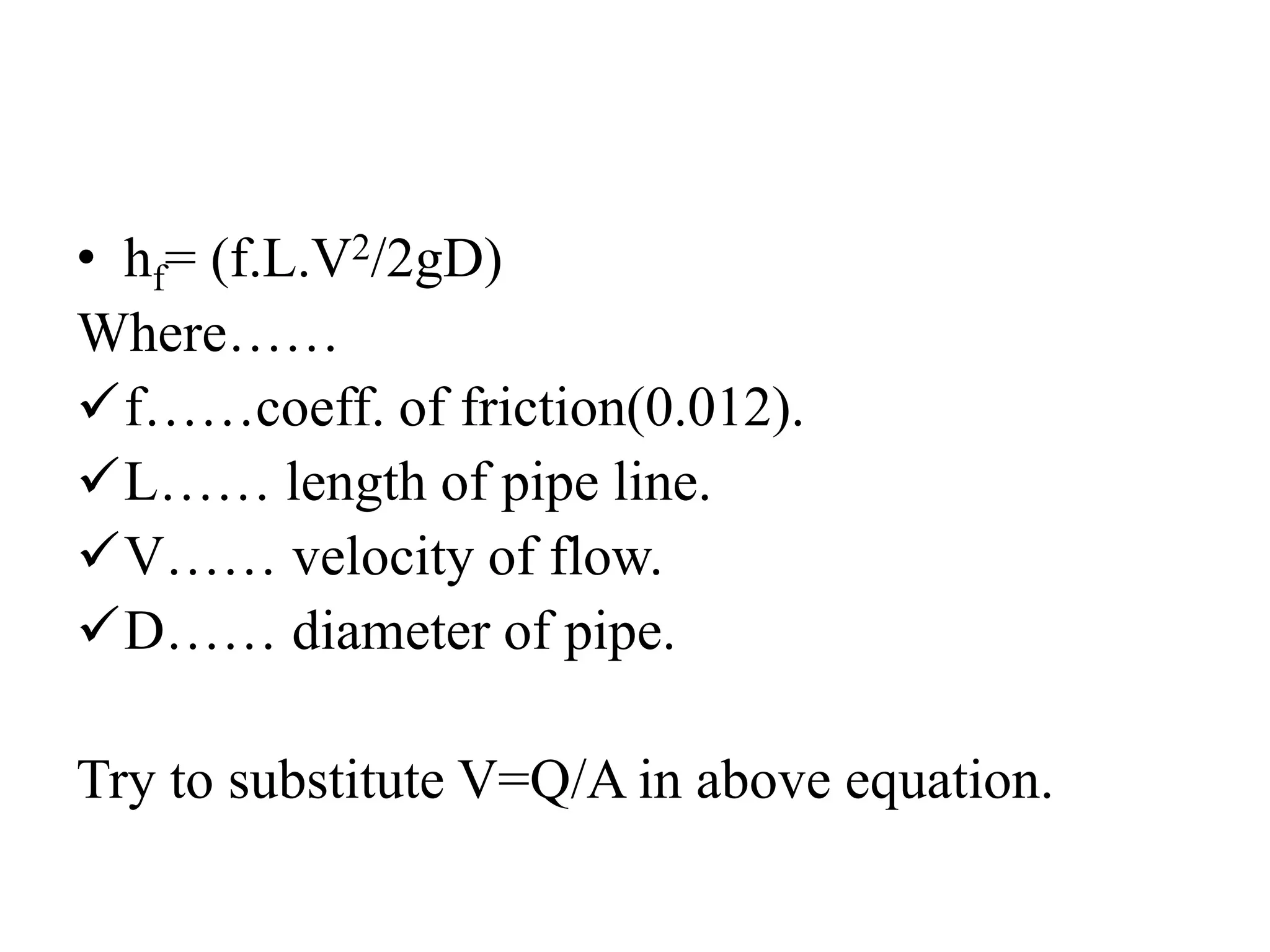
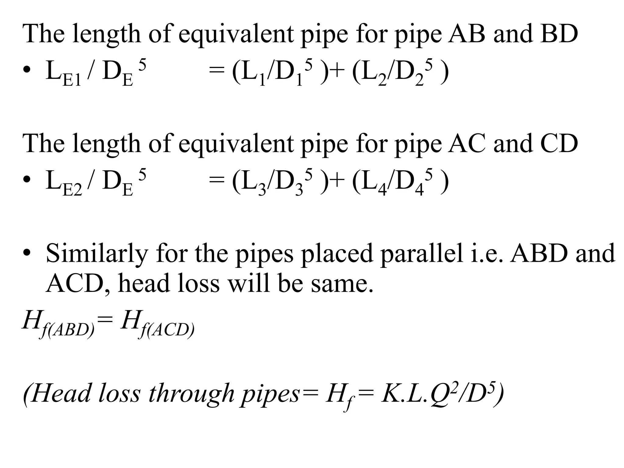
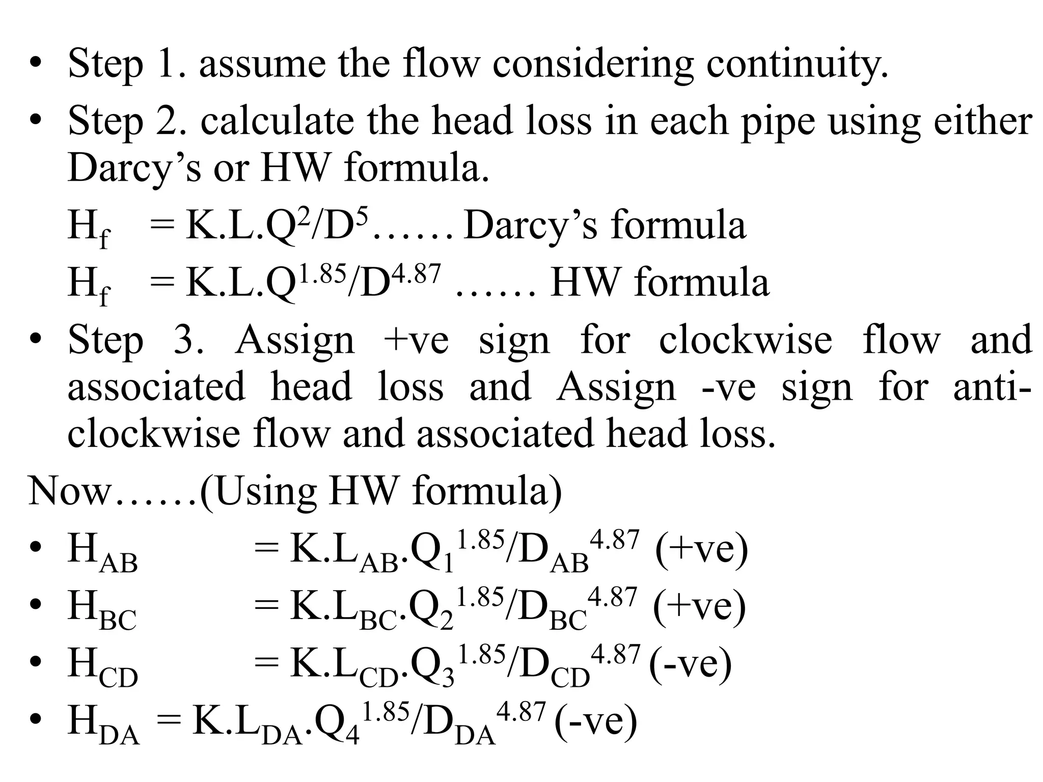
![• Hf(ABD)= (K.L1Q1
2/D1
5 )+ (K.L2.Q1
2/D2
5)
• Hf(ACD)= (K.L3Q2
2/D3
5 )+ (K.L4.Q2
2/D4
5)
Now…
(K.L1Q1
2/D1
5 )+ (K.L2.Q1
2/D2
5) = (K.L3Q2
2/D3
5 )+ (K.L4.Q2
2/D4
5)
(K.L1Q1
2/D1
5 )+ (K.L2.Q1
2/D2
5) = (K.L3Q2
2/D3
5 )+ (K.L4.Q2
2/D4
5)
(L1Q1
2/D1
5 )+ (L2.Q1
2/D2
5) = (L3Q2
2/D3
5 )+ (L4.Q2
2/D4
5)
Q1
2 [(L1/D1
5 )+ (L2/D2
5)] = Q2
2 [(L3/D3
5 )+ (L4/D4
5)]
Q1
2 / Q2
2 = [(L3/D3
5 )+ (L4/D4
5)] / [(L1/D1
5 )+ (L2/D2
5)]
Q1 / Q2 = sqrt {[(L3/D3
5 )+ (L4/D4
5)] / [(L1/D1
5 )+ (L2/D2
5)] }
Q1 / Q2 = A or Q1 = A.Q2 or Q=Q2 (A+1)](https://image.slidesharecdn.com/designofpipenetwork-190227065132/75/Design-of-pipe-network-15-2048.jpg)
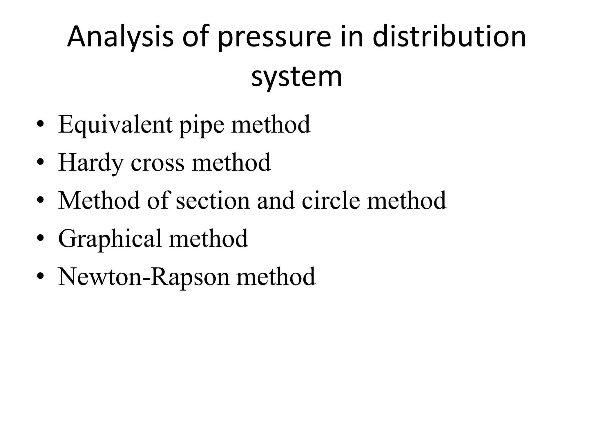
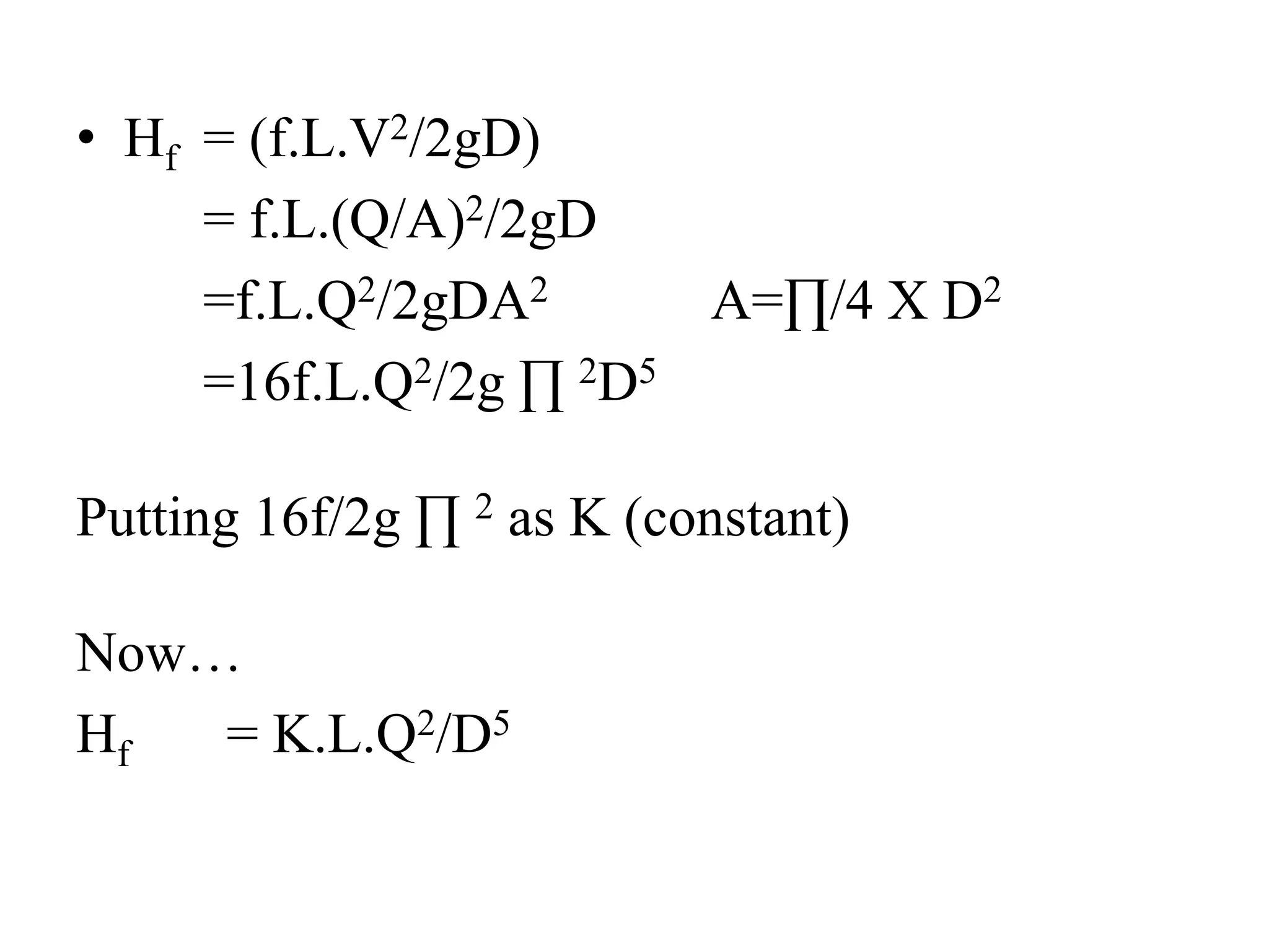
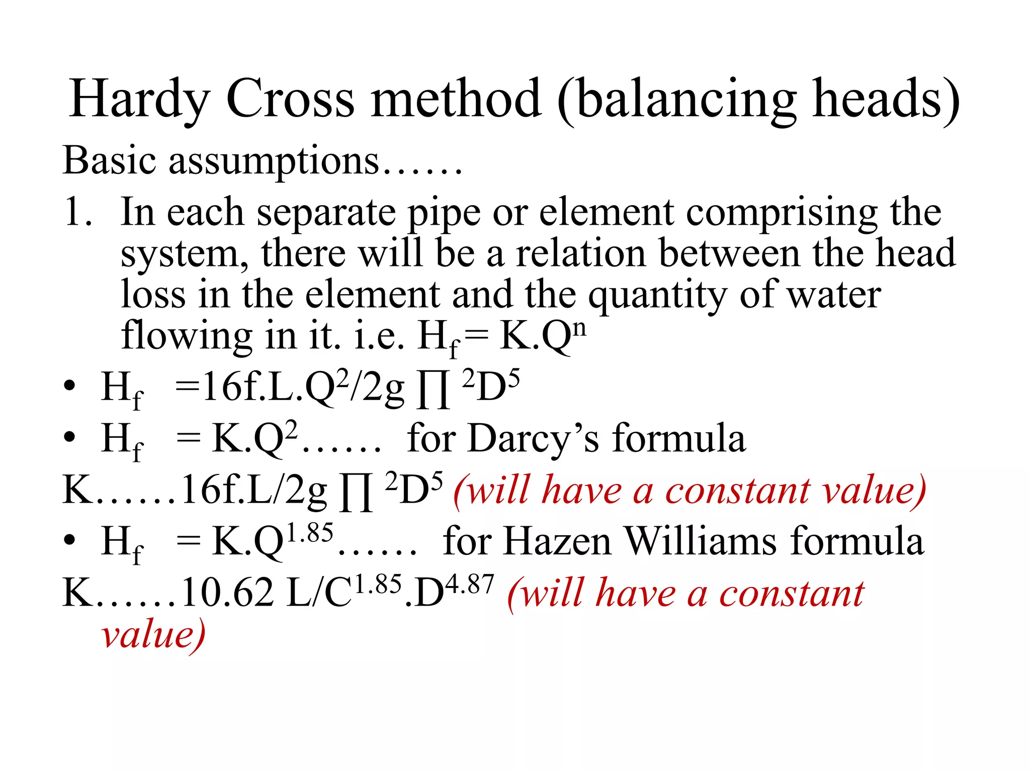
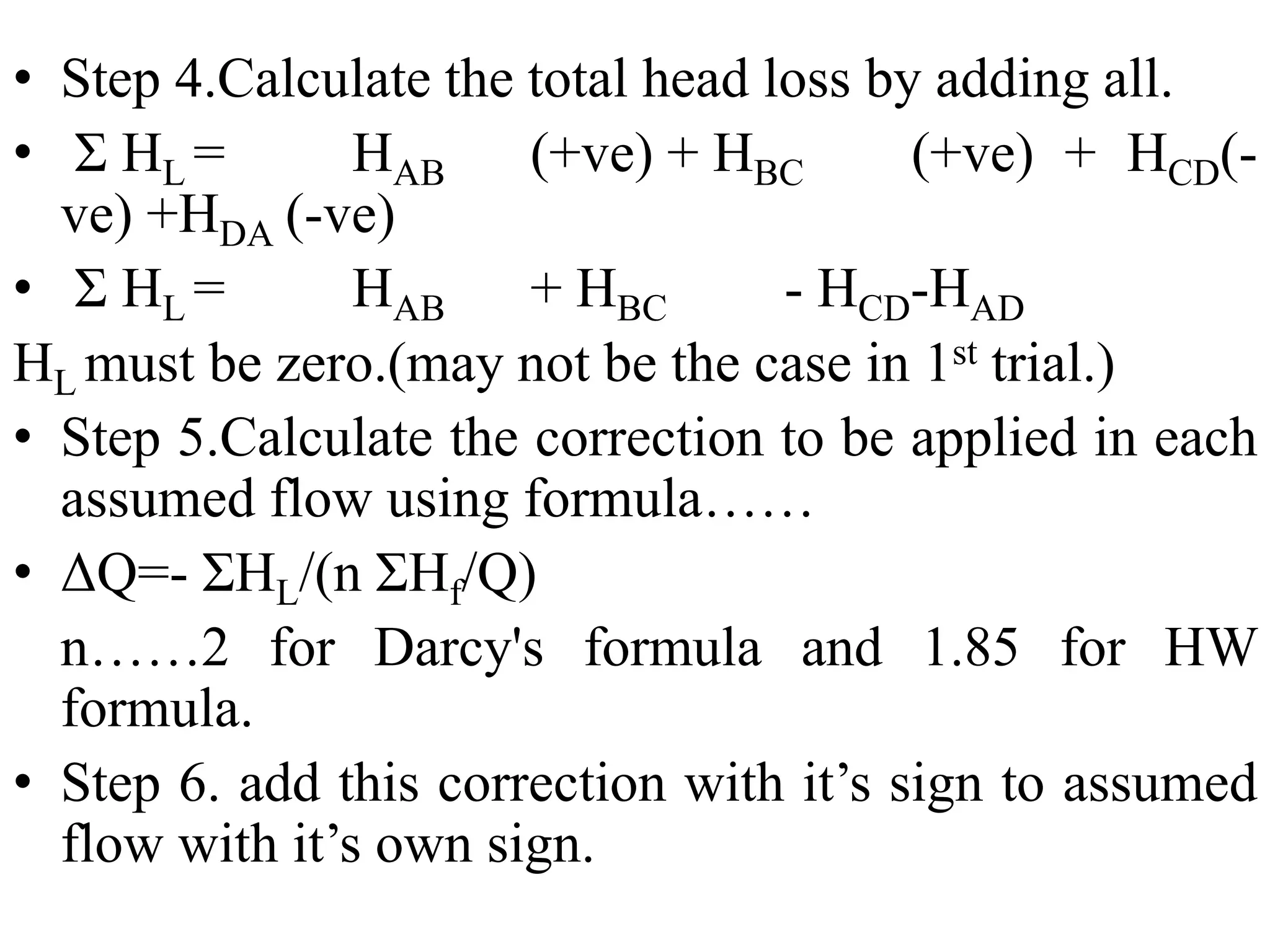
![Now if LE and DE are the properties of equivalent
pipe replacing whole network it should able to
carry the total flow ‘Q’ and should have same head
loss i.e. Hf(ABD) or Hf(ACD)
K.LEQ2/DE
5 =(K.L3Q2
2/D3
5 )+ (K.L4.Q2
2/D4
5)
LEQ2/DE
5 = (L3Q2
2/D3
5 )+ (L4.Q2
2/D4
5)
As ……Q=Q2 (A+1)
LE[Q2 (A+1)]2/DE
5 = (L3Q2
2/D3
5 )+ (L4.Q2
2/D4
5)
LE /DE
5= [(L3Q2
2/D3
5)+(L4.Q2
2/D4
5)] / (A+1)2
LE = DE
5 .[(L3Q2
2/D3
5)+(L4.Q2
2/D4
5)] / (A+1)2](https://image.slidesharecdn.com/designofpipenetwork-190227065132/75/Design-of-pipe-network-16-2048.jpg)
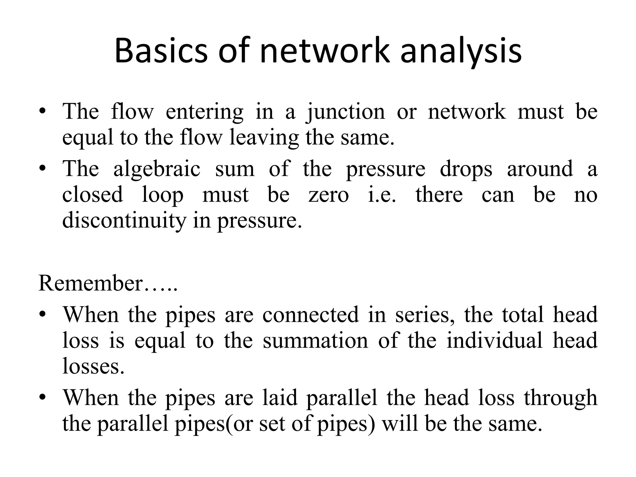
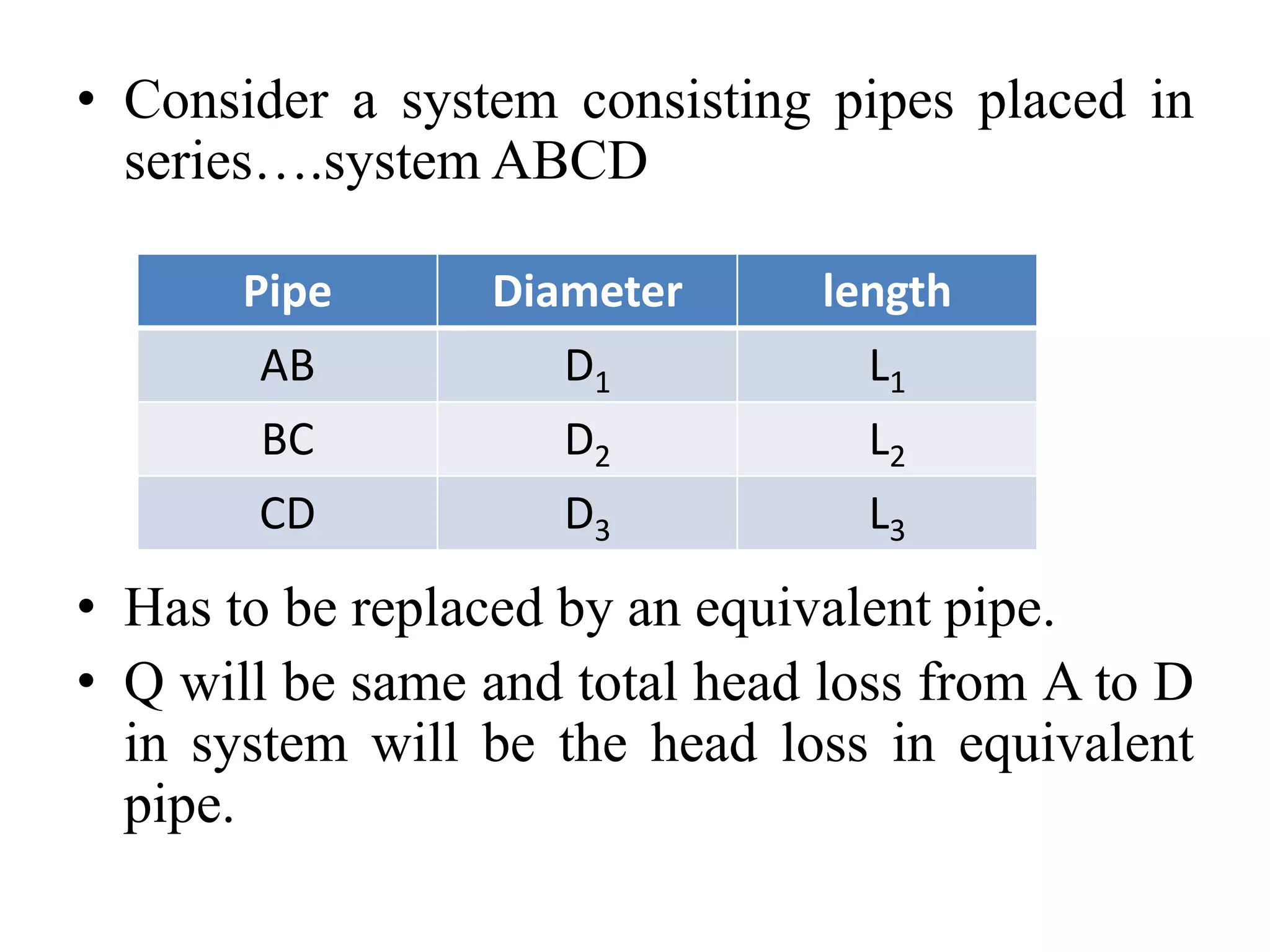
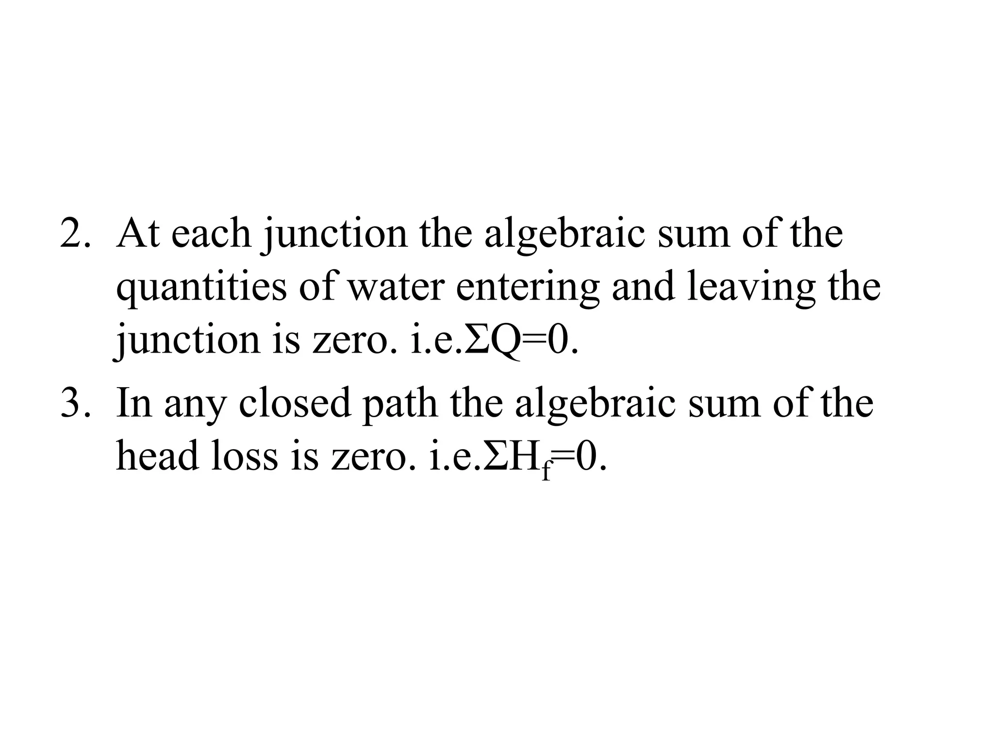
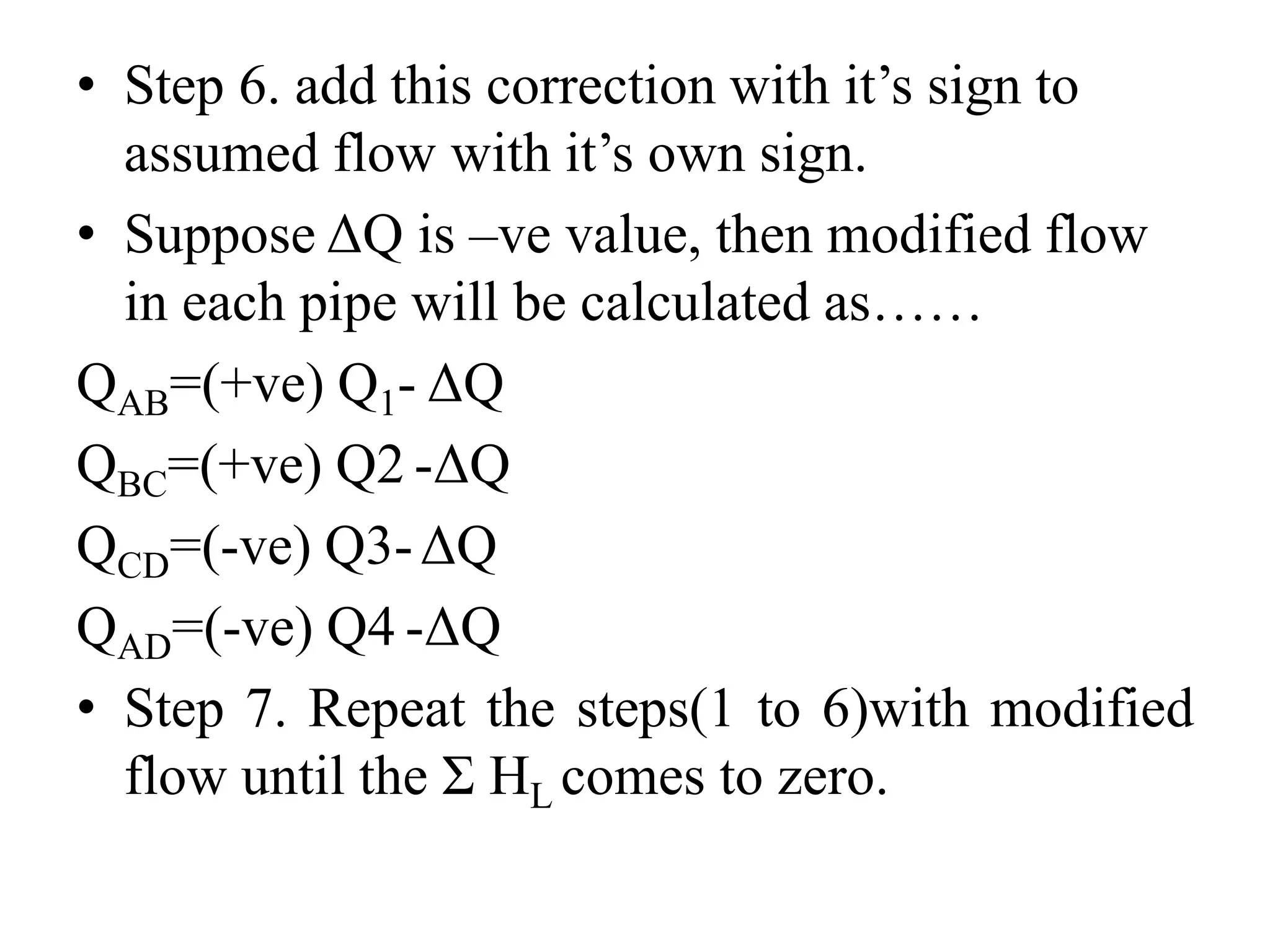
![• Important…..
All above derivations are based on Darcy’s formula.
If Hazen Williams formula has to be used the
equivalent length can be calculated using
following modifications……
For pipes in series……
LE / DE
4.87 = (L1/D1
4.87 )+ (L2/D2
4.87 )+(L3/D3
4.87)
For parallel pipes……
LE /DE
4.87= [(L3Q2
1.85/D3
4.87)+(L4.Q2
1.85/D4
4.87)] / (A+1)2](https://image.slidesharecdn.com/designofpipenetwork-190227065132/75/Design-of-pipe-network-17-2048.jpg)


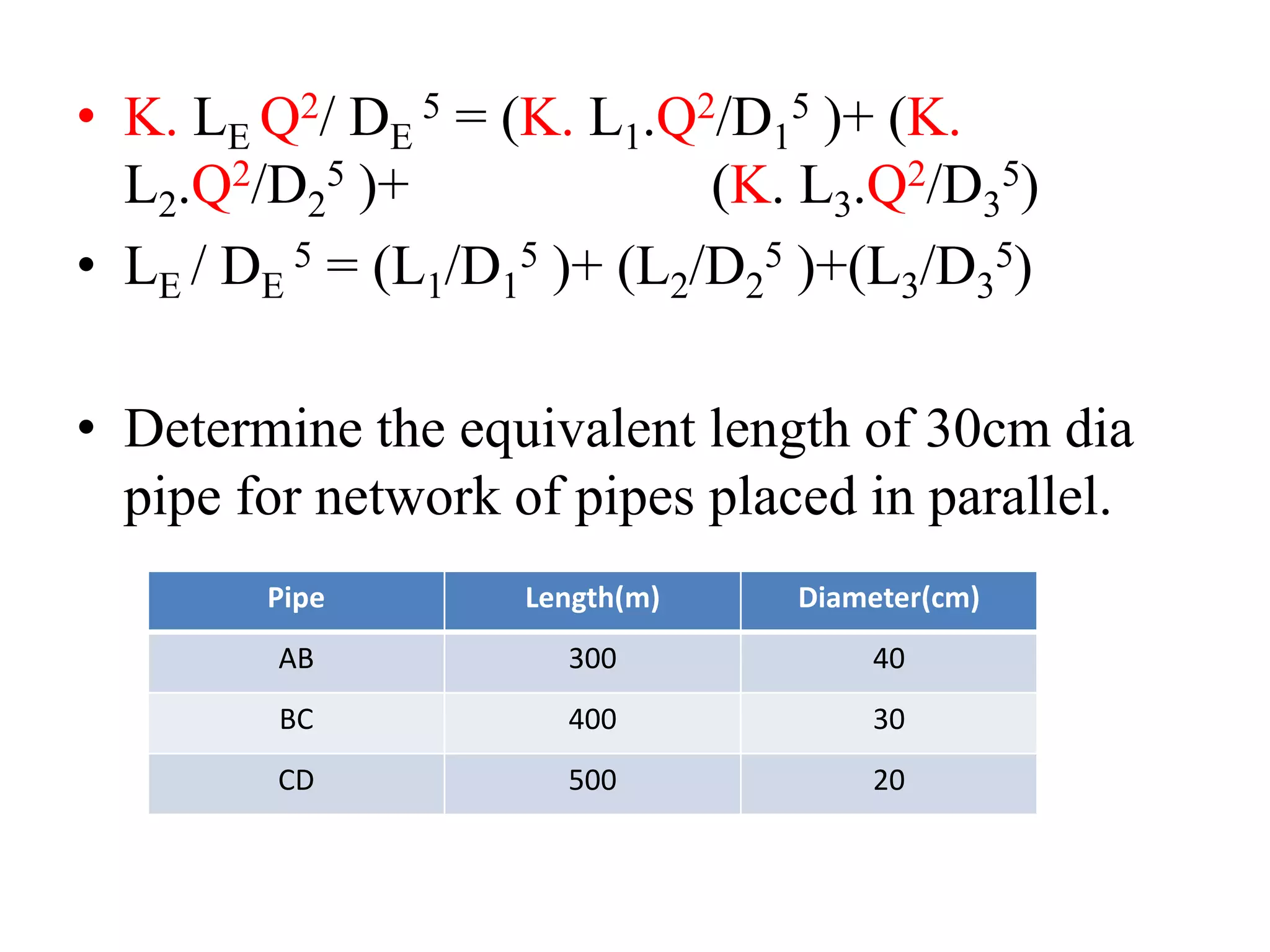
The document discusses the design of pipe networks for water distribution. It describes various methods for analyzing pressure in distribution systems, including the equivalent pipe method, Hardy Cross method, and graphical method. The equivalent pipe method involves replacing a complex pipe system with a single hydraulically equivalent pipe. The document provides detailed steps for applying the equivalent pipe method to pipes placed in series and parallel. It also describes the Hardy Cross method which balances heads by iteratively correcting assumed pipe flows until the total head loss equals zero.