The document discusses flow of fluids in pipelines including:
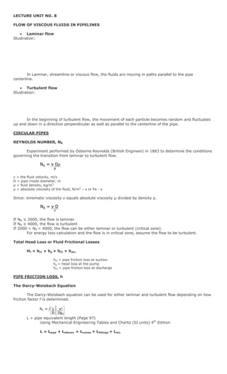
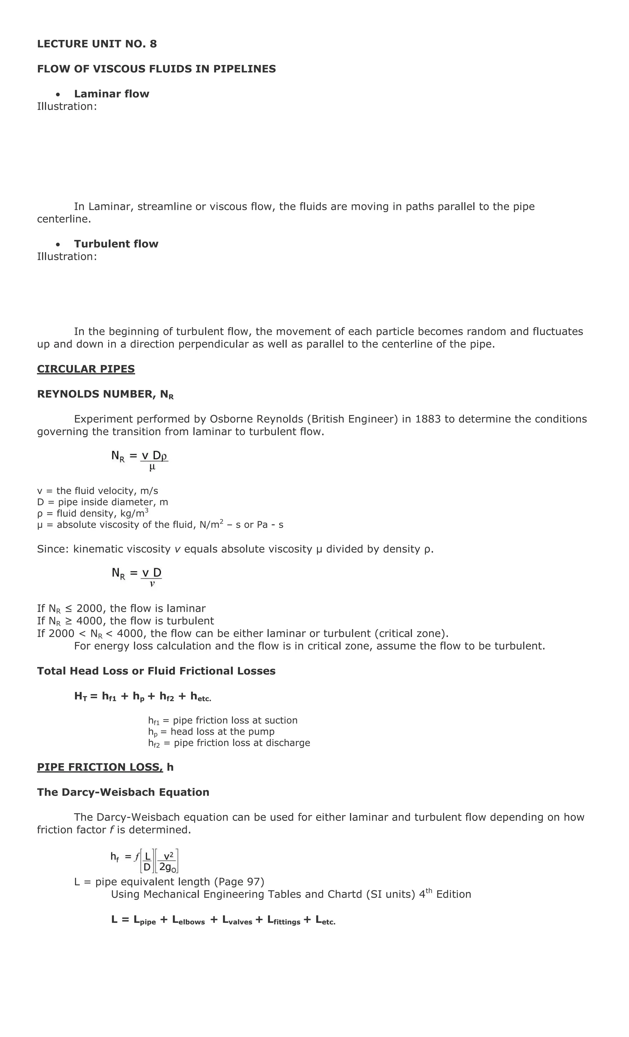
1. Laminar and turbulent flow and the factors that determine the transition between the two such as Reynolds number.
2. Methods for calculating head losses and pressure drops in pipes due to friction including the Darcy-Weisbach equation.
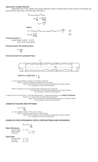
3. Factors that affect friction losses such as pipe roughness, geometry, and flow characteristics.
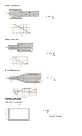
4. Analysis of flow in non-circular pipes using concepts like hydraulic diameter.
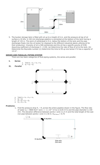
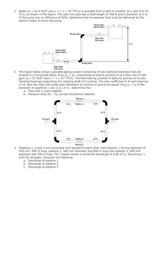
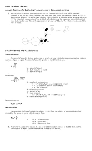
5. Examples of problems calculating flow characteristics like velocity and pressure changes in series and parallel pipe networks.