Download as PDF, PPTX

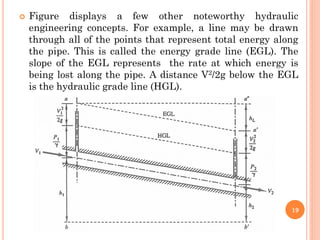
![ Under ordinary circumstances, water loses energy as it
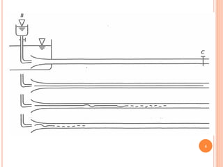
flows through a pipe. A major portion of the energy loss
is caused by
1. friction against the pipe walls and
2. viscous dissipation occurring throughout the flow.
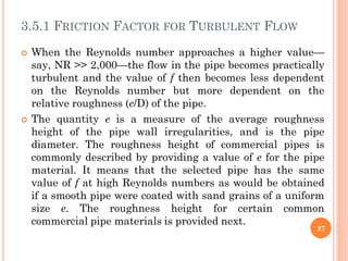
Wall friction on a moving column of water depends on
the roughness of the wall material (e) and the velocity
gradient [(dV/dr)] at the wall. For the same flow rate, it
is evident in next Figure that turbulent flow has a
higher wall velocity gradient than that of laminar flow;
hence, a higher friction loss may be expected as the
Reynolds number increases.
8](https://image.slidesharecdn.com/ch3-221218124033-0e88afd4/85/Ch-3-pdf-8-320.jpg)
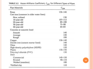
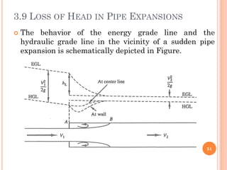
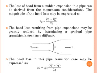
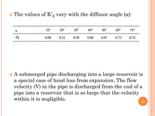
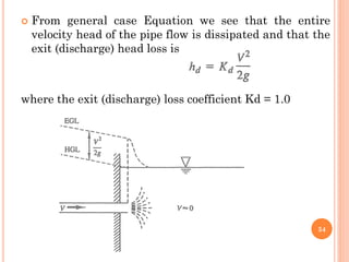


1) The document discusses water flow in pipes, including descriptions of laminar and turbulent flow, the Reynolds number, energy in pipe flow, and head loss from pipe friction. 2) Key concepts covered include the Darcy-Weisbach equation for calculating head loss from pipe friction and empirical equations like the Hazen-Williams equation. 3) Friction factors are discussed for both laminar and turbulent flow and their relationship to parameters like the Reynolds number and pipe roughness.