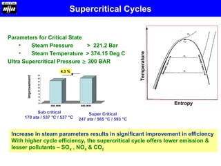
Parameters for CriticalState
• Steam Pressure > 221.2 Bar
• Steam Temperature > 374.15 Deg C
Ultra Supercritical Pressure 300 BAR
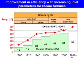
Increase in steam parameters results in significant improvement in efficiency
With higher cycle efficiency, the supercritical cycle offers lower emission &
lesser pollutants – SOX , NOX & CO2
0
5
10
15
20
25
30
35
40
45
500 MW 660 MW
Sub critical
170 ata / 537 °C / 537 °C
Super Critical
247 ata / 565 °C / 593 °C
Improvement
4.3 %
Entropy
Temperature
Supercritical Cycles
5.
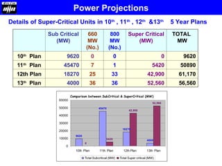
Details of Super-CriticalUnits in 10th
, 11th
, 12th
&13th
5 Year Plans
Sub Critical
(MW)
660
MW
(No.)
800
MW
(No.)
Super Critical
(MW)
TOTAL
MW
10th
Plan 9620 0 0 0 9620
11th
Plan 45470 7 1 5420 50890
12th Plan 18270 25 33 42,900 61,170
13th
Plan 4000 36 36 52,560 56,560
Power Projections
Comparison between SubCritical & SuperCritical (MW)
9620
45470
18270
4000
0
5420
42,900
52,560
0
10000
20000
30000
40000
50000
60000
10th Plan 11th Plan 12th Plan 13th Plan
Total Subcritical (MW) Total Super critical (MW)
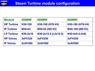
Module 500MW 660MW800MW
HP Turbine H30-100 H30-100 (H70-V4) H30-100 (H70-V4)
IP Turbine M30-63 M30-63 (I50-V2) M30-100 (I60-V2)
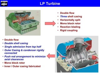
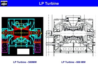
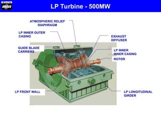
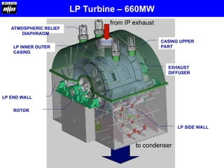
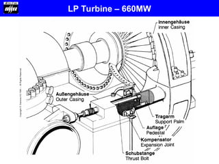
LP Turbine N30-2x10 N30-2x12.5 (L2x12.5) N30-4x8 (L4x8)
HP Valves 2xFV320 2xFV250 2xFV250
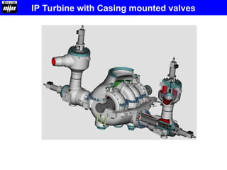
IP Valves 2xAV560 2xAV560 2xAV560
Steam Turbine module configuration
11.
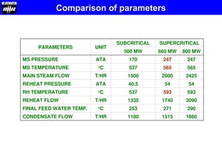
PARAMETERS UNIT
SUBCRITICAL SUPERCRITICAL
500MW 660 MW 800 MW
MS PRESSURE ATA 170 247 247
MS TEMPERATURE o
C 537 565 565
MAIN STEAM FLOW T/HR 1500 2000 2425
REHEAT PRESSURE ATA 40.5 54 54
RH TEMPERATURE o
C 537 593 593
REHEAT FLOW T/HR 1335 1740 2090
FINAL FEED WATER TEMP. o
C 253 271 290
CONDENSATE FLOW T/HR 1180 1515 1860
Comparison of parameters
12.
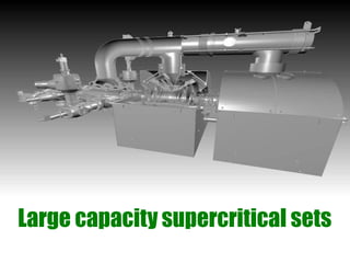
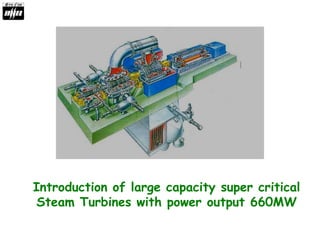
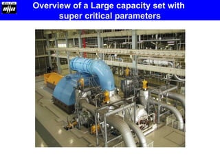
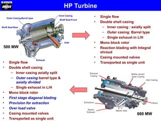
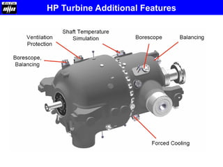
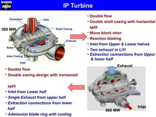
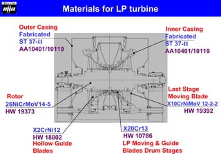
Overview of aLarge capacity set with
super critical parameters
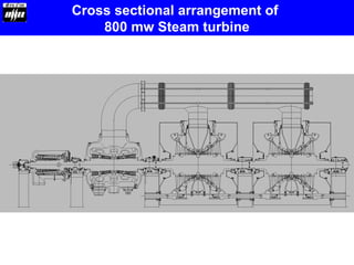
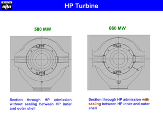
Section through HPadmission with
sealing between HP inner and outer
shell
Section through HP admission
without sealing between HP inner
and outer shell
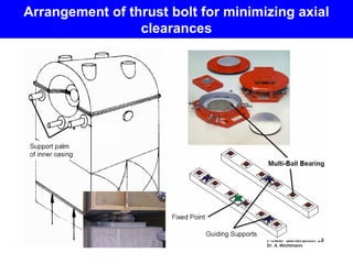
500 MW 660 MW
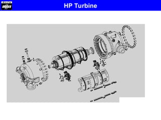
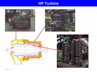
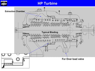
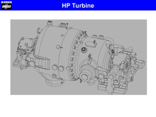
HP Turbine
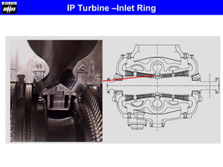
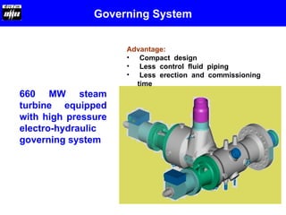
Governing System
660 MWsteam
turbine equipped
with high pressure
electro-hydraulic
governing system
Advantage:
• Compact design
• Less control fluid piping
• Less erection and commissioning
time
42.
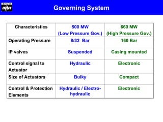
Characteristics 500 MW
(LowPressure Gov.)
660 MW
(High Pressure Gov.)
Operating Pressure 8/32 Bar 160 Bar
IP valves Suspended Casing mounted
Control signal to
Actuator
Hydraulic Electronic
Size of Actuators Bulky Compact
Control & Protection
Elements
Hydraulic / Electro-
hydraulic
Electronic
Governing System
43.
Advantages of highpressure EHA based governing system
• Bulky servomotors replaced with compact
actuators leading to compact layout in TG hall
• Governing & protection racks replaced by
electronic systems
• Faster response due to state of art electronic
control and protection systems
• Reduced manufacturing time at shop
• Turbine driven MOP replaced with motor driven
pump
• Mechanical Emergency governor replaced by
electronic protection system, eliminating actual
over speeding at site
44.
Additional features
• Lessnoise because of latest features hence no
cleading up to 85 db
• Hydraulic turning wheel for barring replaced by
Hydraulic turning motor at front bearing pedestal
similar to 250 MW
• Steam strainer elements built in the valves resulting
in elimination of strainer housings
45.
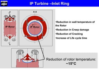
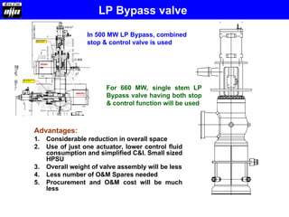
LP Bypass valve
Advantages:
1.Considerable reduction in overall space
2. Use of just one actuator, lower control fluid
consumption and simplified C&I. Small sized
HPSU
3. Overall weight of valve assembly will be less
4. Less number of O&M Spares needed
5. Procurement and O&M cost will be much
less
In 500 MW LP Bypass, combined
stop & control valve is used
For 660 MW, single stem LP
Bypass valve having both stop
& control function will be used
46.
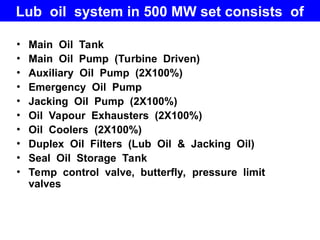
Lub oil systemin 500 MW set consists of
• Main Oil Tank
• Main Oil Pump (Turbine Driven)
• Auxiliary Oil Pump (2X100%)
• Emergency Oil Pump
• Jacking Oil Pump (2X100%)
• Oil Vapour Exhausters (2X100%)
• Oil Coolers (2X100%)
• Duplex Oil Filters (Lub Oil & Jacking Oil)
• Seal Oil Storage Tank
• Temp control valve, butterfly, pressure limit
valves
47.
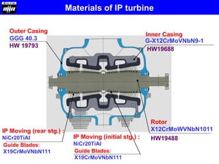
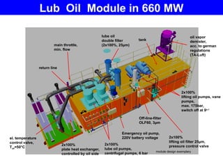
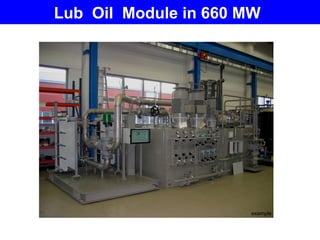
LUB OIL MODULE
el.temperature
control valve,
Toil=50°C
2x100%
lube oil pumps,
centrifugal pumps, 6 bar
Emergency oil pump,
220V battery voltage
2x100%
lifting oil pumps, vane
pumps,
max. 175bar,
switch off at 9s-1
oil vapor
demister,
acc. to german
regulations
(TA-Luft)
main throttle,
min. flow
lube oil
double filter
(2x100%, 25µm)
return line
2x100%
plate heat exchanger,
controlled by oil side
2x100%
lifting oil filter 25µm,
pressure control valve
tank
module design exemplary
Off-line-filter
OLF60, 3µm
Lub Oil Module in 660 MW
• Turbine drivenmain oil pump in 500
MW set is replaced by motor driven
lub oil pump in 660 MW
Advantage:
1. Injectors in system are avoided
2. Interconnecting pipe between injectors &
MOP is no more required
3. Smaller main oil tank
Main Oil Pump
50.
• Electric actuatorsof angle drain
valves replaced by pneumatic
actuators
Advantage:
In case of loss of control air, valves
move immediately in the defined fail safe
position.
A motorised valve remains in the actual
position in case of power loss and need
to be operated manually
Drain Valves
51.
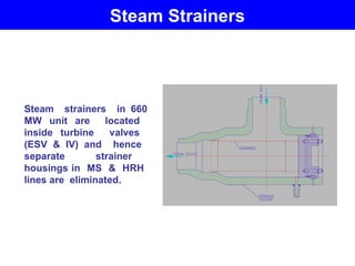
Steam Strainers
Steam strainersin 660
MW unit are located
inside turbine valves
(ESV & IV) and hence
separate strainer
housings in MS & HRH
lines are eliminated.
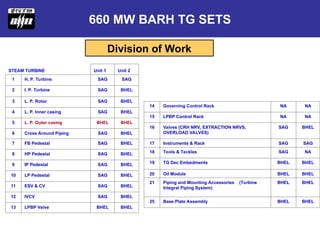
STEAM TURBINE Unit1 Unit 2
1 H. P. Turbine SAG SAG
2 I. P. Turbine SAG BHEL
3 L. P. Rotor SAG BHEL
4 L. P. Inner casing SAG BHEL
5 L. P. Outer casing BHEL BHEL
6 Cross Around Piping SAG BHEL
7 FB Pedestal SAG BHEL
8 HP Pedestal SAG BHEL
9 IP Pedestal SAG BHEL
10 LP Pedestal SAG BHEL
11 ESV & CV SAG BHEL
12 IVCV SAG BHEL
13 LPBP Valve BHEL BHEL
14 Governing Control Rack NA NA
15 LPBP Control Rack NA NA
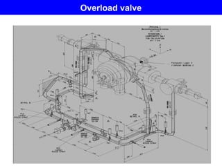
16 Valves (CRH NRV, EXTRACTION NRVS,
OVERLOAD VALVES)
SAG BHEL
17 Instruments & Rack SAG SAG
18 Tools & Tackles SAG NA
19 TG Dec Embedments BHEL BHEL
20 Oil Module BHEL BHEL
21 Piping and Mounting Accessories (Turbine
Integral Piping System)
BHEL BHEL
25 Base Plate Assembly BHEL BHEL
800 MW TG SETS
660 MW BARH TG SETS
Division of Work
54.
660 MW TGSETS
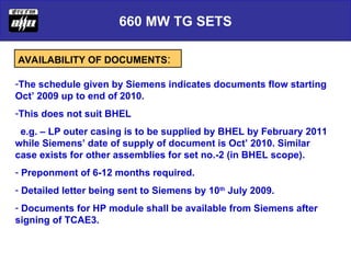
AVAILABILITY OF DOCUMENTS:
-The schedule given by Siemens indicates documents flow starting
Oct’ 2009 up to end of 2010.
-This does not suit BHEL
e.g. – LP outer casing is to be supplied by BHEL by February 2011
while Siemens’ date of supply of document is Oct’ 2010. Similar
case exists for other assemblies for set no.-2 (in BHEL scope).
- Preponment of 6-12 months required.
- Detailed letter being sent to Siemens by 10th
July 2009.
- Documents for HP module shall be available from Siemens after
signing of TCAE3.
55.
660 MW TGSETS
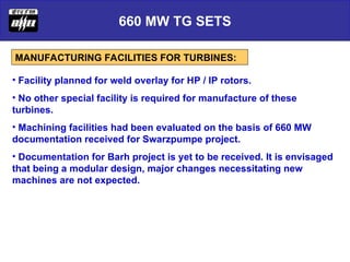
MANUFACTURING FACILITIES FOR TURBINES:
• Facility planned for weld overlay for HP / IP rotors.
• No other special facility is required for manufacture of these
turbines.
• Machining facilities had been evaluated on the basis of 660 MW
documentation received for Swarzpumpe project.
• Documentation for Barh project is yet to be received. It is envisaged
that being a modular design, major changes necessitating new
machines are not expected.


![Amardeep jadeja copy.ppt [autosaved]](https://cdn.slidesharecdn.com/ss_thumbnails/amardeepjadeja-copy-pptautosaved-111008011305-phpapp02-thumbnail.jpg?width=640&height=640&fit=bounds)


