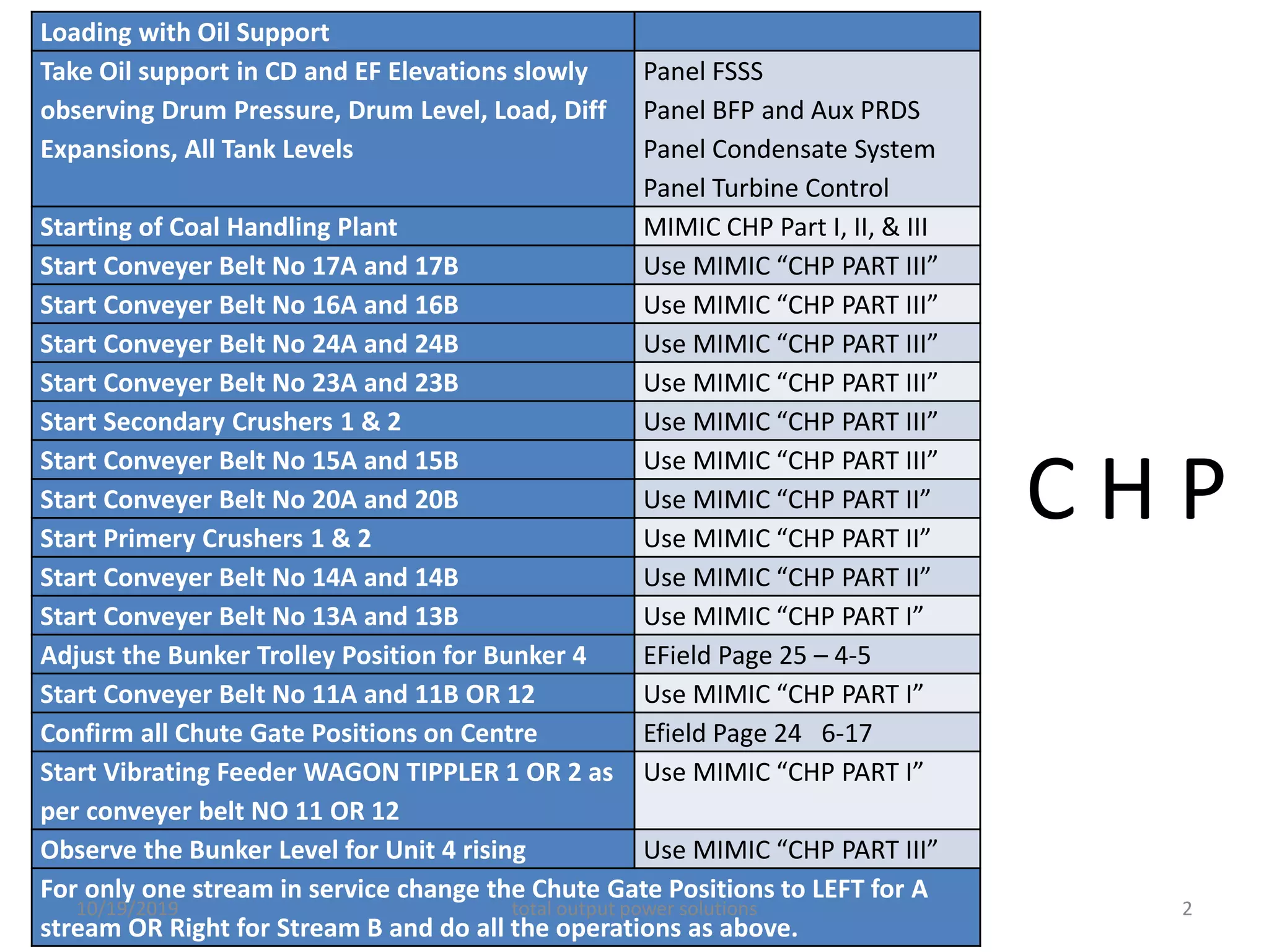
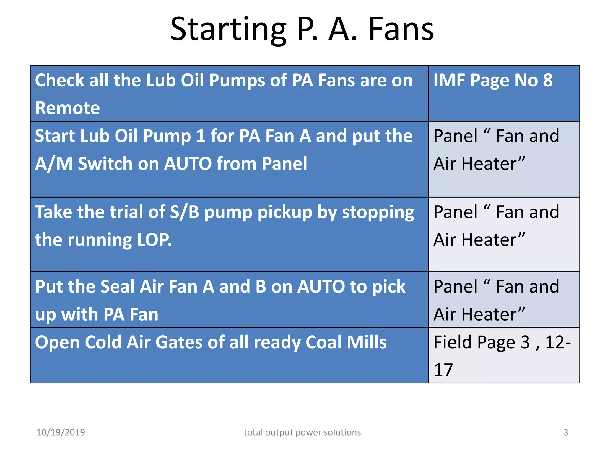
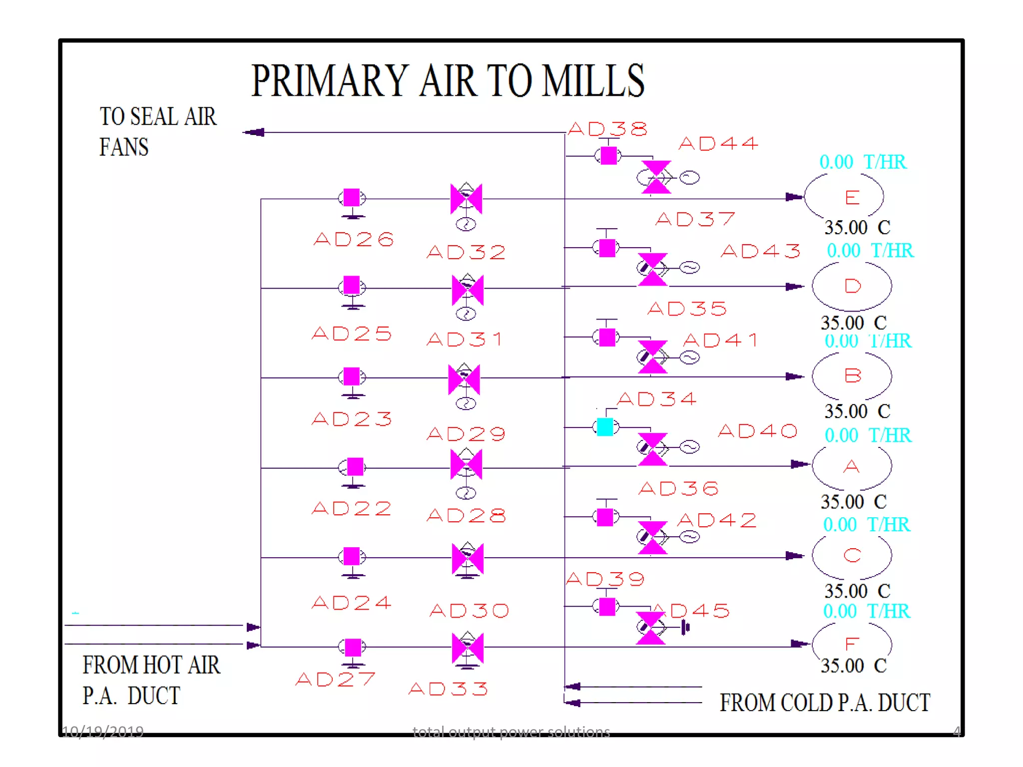
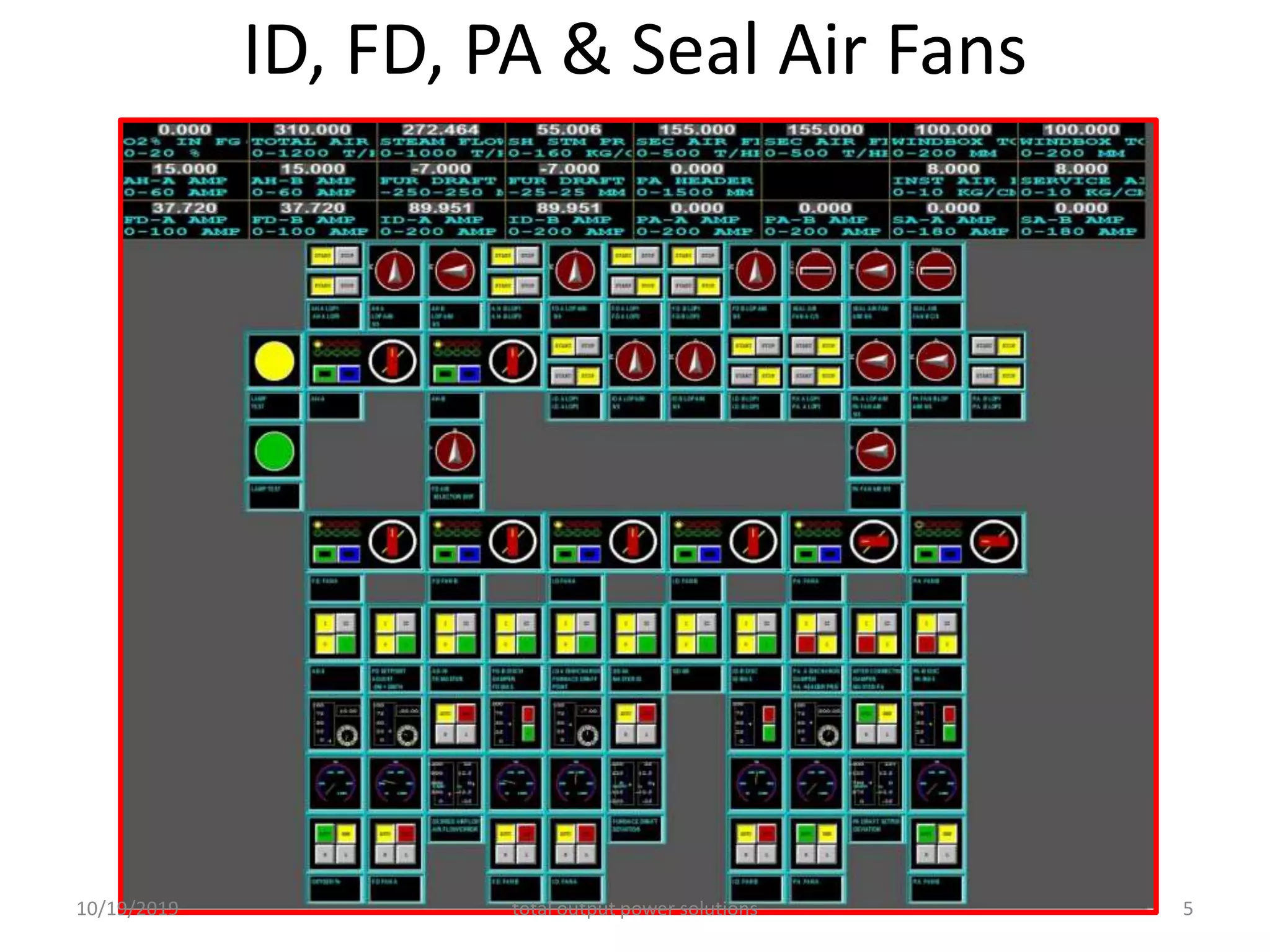
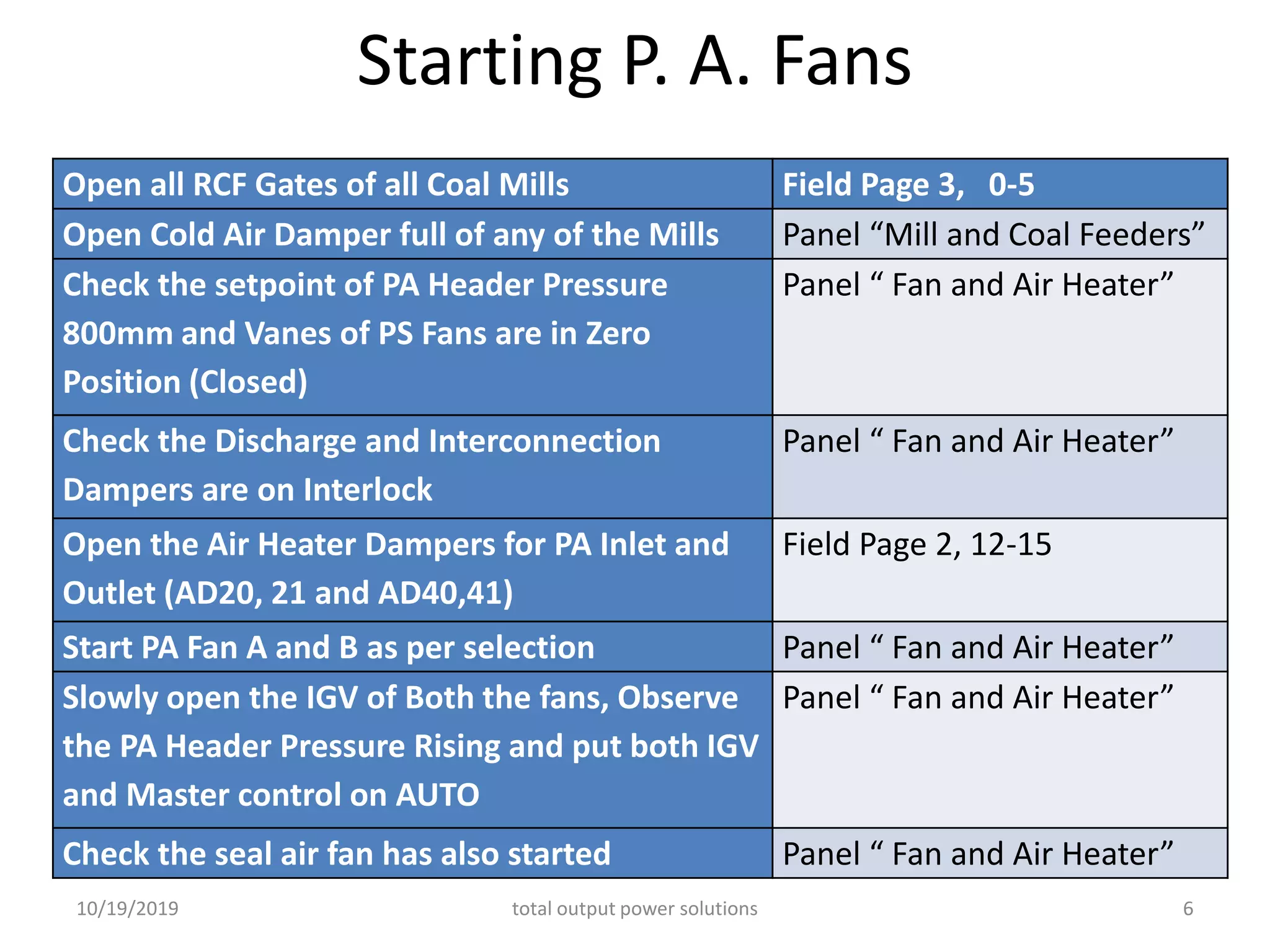
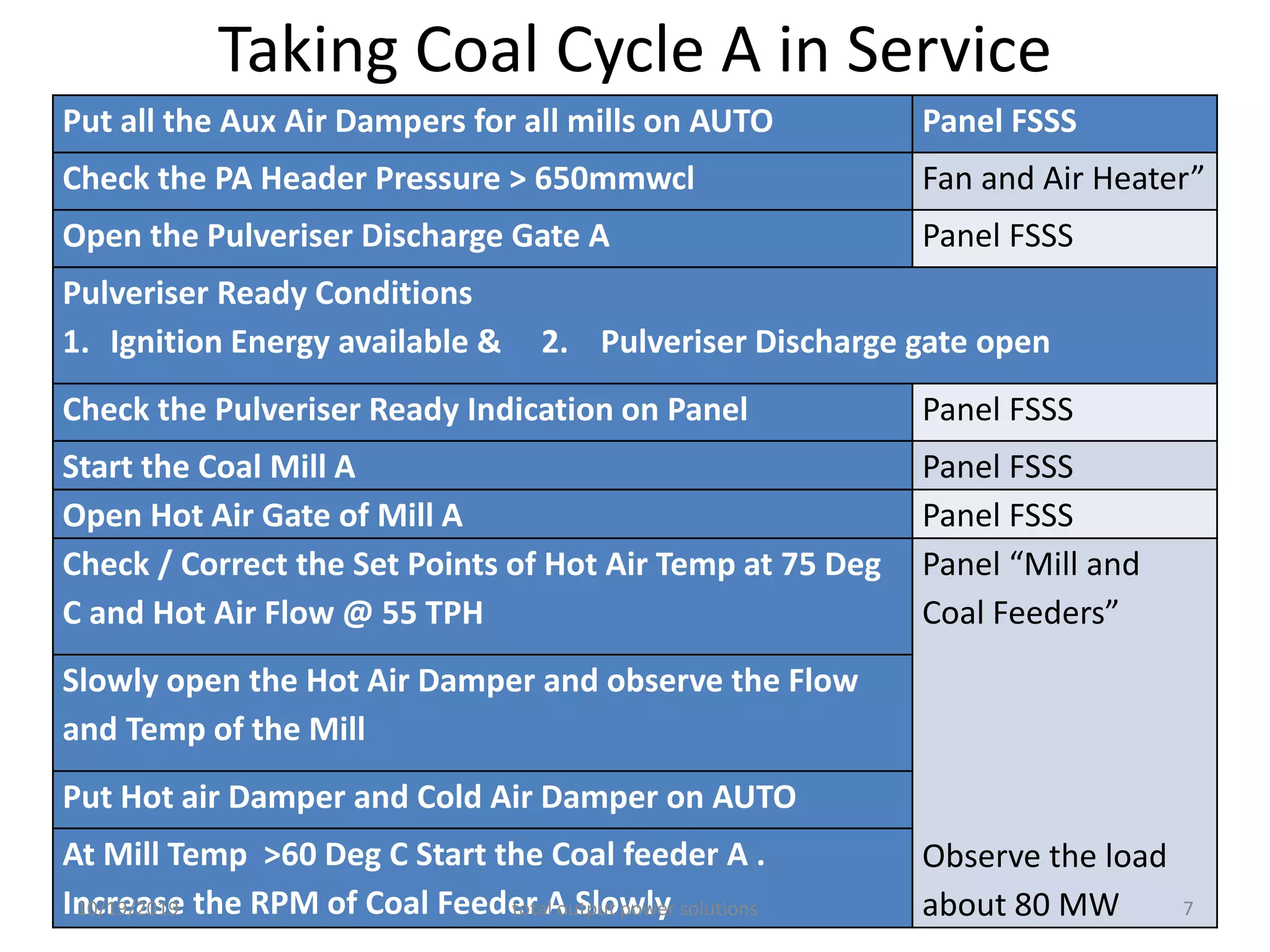
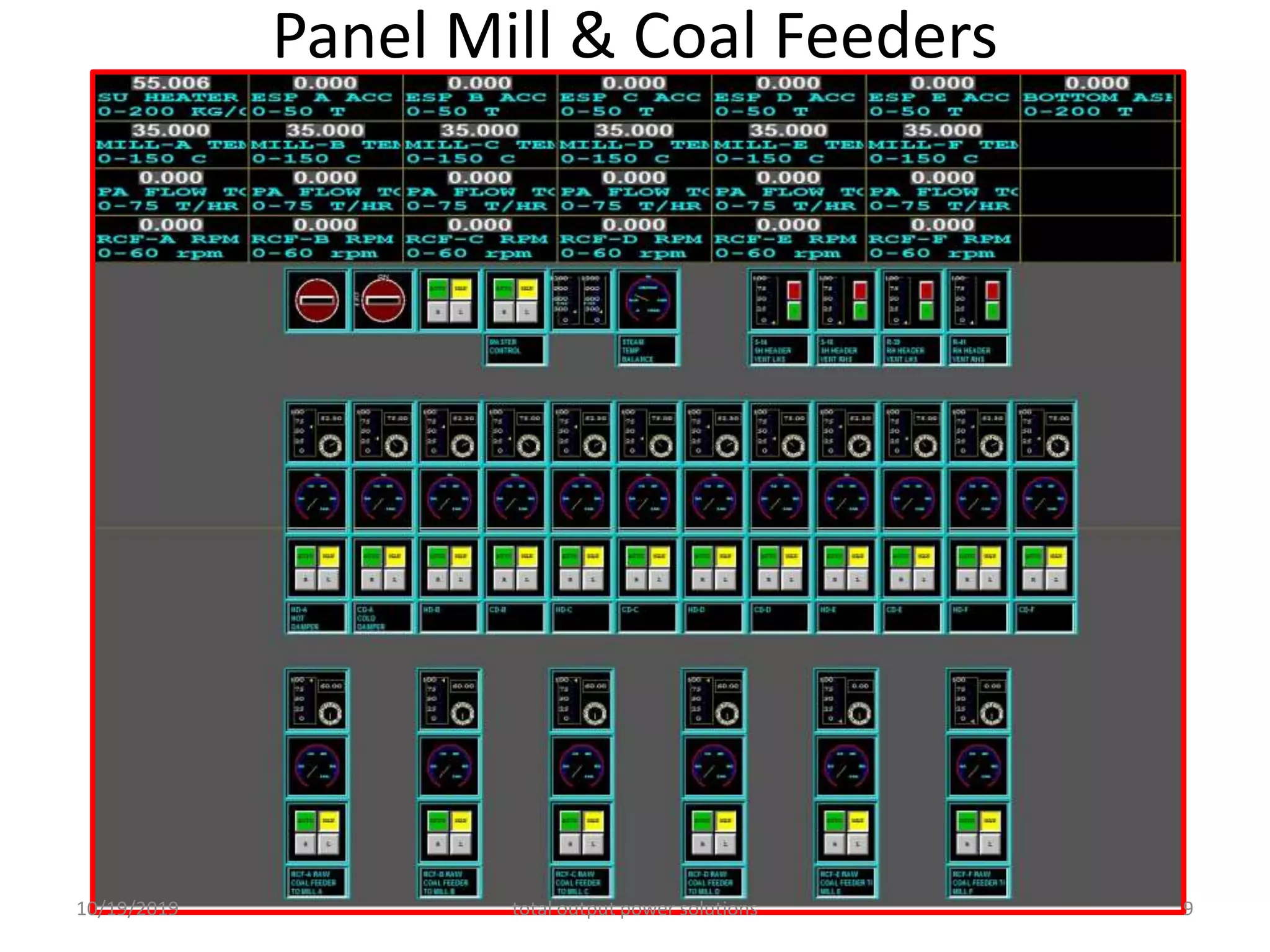
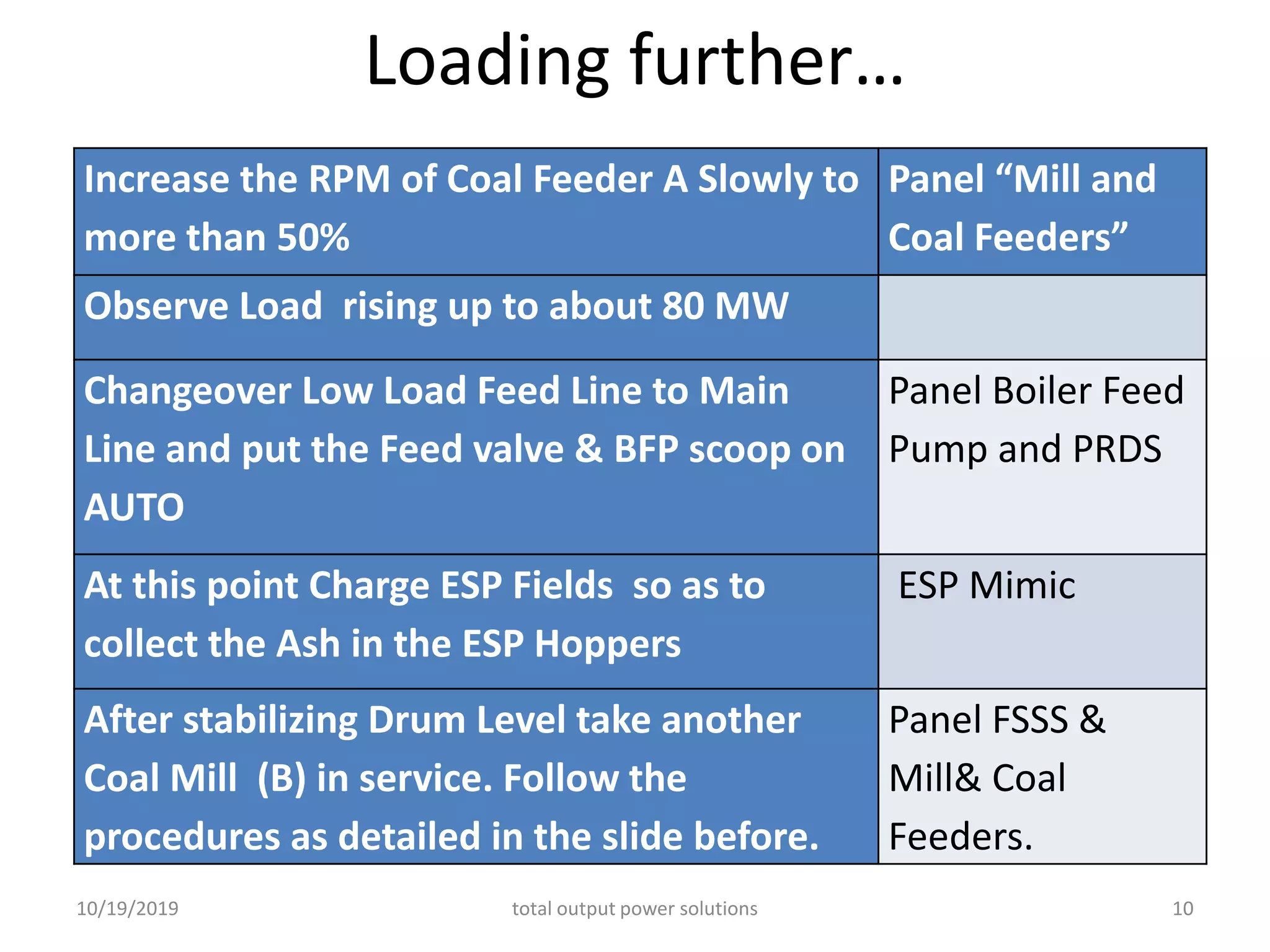
THERMAL POWER PLANT
OPERATIONS
Simulator Part 7- Day 4
MANOHAR TATWAWADI
Director, tops
A2-806, PALLADION, BALEWADI, PUNE 411045
Mob: 9372167165, Email:-mtatwawadi@gmail.com
10/19/2019 total output power solutions 1
C H P
Loading with Oil Support
Take Oil support in CD and EF Elevations slowly
observing Drum Pressure, Drum Level, Load, Diff
Expansions, All Tank Levels
Panel FSSS
Panel BFP and Aux PRDS
Panel Condensate System
Panel Turbine Control
Starting of Coal Handling Plant MIMIC CHP Part I, II, & III
Start Conveyer Belt No 17A and 17B Use MIMIC “CHP PART III”
Start Conveyer Belt No 16A and 16B Use MIMIC “CHP PART III”
Start Conveyer Belt No 24A and 24B Use MIMIC “CHP PART III”
Start Conveyer Belt No 23A and 23B Use MIMIC “CHP PART III”
Start Secondary Crushers 1 & 2 Use MIMIC “CHP PART III”
Start Conveyer Belt No 15A and 15B Use MIMIC “CHP PART III”
Start Conveyer Belt No 20A and 20B Use MIMIC “CHP PART II”
Start Primery Crushers 1 & 2 Use MIMIC “CHP PART II”
Start Conveyer Belt No 14A and 14B Use MIMIC “CHP PART II”
Start Conveyer Belt No 13A and 13B Use MIMIC “CHP PART I”
Adjust the Bunker Trolley Position for Bunker 4 EField Page 25 – 4-5
Start Conveyer Belt No 11A and 11B OR 12 Use MIMIC “CHP PART I”
Confirm all Chute Gate Positions on Centre Efield Page 24 6-17
Start Vibrating Feeder WAGON TIPPLER 1 OR 2 as
per conveyer belt NO 11 OR 12
Use MIMIC “CHP PART I”
Observe the Bunker Level for Unit 4 rising Use MIMIC “CHP PART III”
For only one stream in service change the Chute Gate Positions to LEFT for A
stream OR Right for Stream B and do all the operations as above.
10/19/2019 total output power solutions 2
Starting P. A. Fans
Check all the Lub Oil Pumps of PA Fans are on
Remote
IMF Page No 8
Start Lub Oil Pump 1 for PA Fan A and put the
A/M Switch on AUTO from Panel
Panel “ Fan and
Air Heater”
Take the trial of S/B pump pickup by stopping
the running LOP.
Panel “ Fan and
Air Heater”
Put the Seal Air Fan A and B on AUTO to pick
up with PA Fan
Panel “ Fan and
Air Heater”
Open Cold Air Gates of all ready Coal Mills Field Page 3 , 12-
17
10/19/2019 total output power solutions 3
PRIMARY AIR TO MILLS
10/19/2019 total output power solutions 4
ID, FD, PA & Seal Air Fans
10/19/2019 total output power solutions 5
Starting P. A. Fans
Open all RCF Gates of all Coal Mills Field Page 3, 0-5
Open Cold Air Damper full of any of the Mills Panel “Mill and Coal Feeders”
Check the setpoint of PA Header Pressure
800mm and Vanes of PS Fans are in Zero
Position (Closed)
Panel “ Fan and Air Heater”
Check the Discharge and Interconnection
Dampers are on Interlock
Panel “ Fan and Air Heater”
Open the Air Heater Dampers for PA Inlet and
Outlet (AD20, 21 and AD40,41)
Field Page 2, 12-15
Start PA Fan A and B as per selection Panel “ Fan and Air Heater”
Slowly open the IGV of Both the fans, Observe
the PA Header Pressure Rising and put both IGV
and Master control on AUTO
Panel “ Fan and Air Heater”
Check the seal air fan has also started Panel “ Fan and Air Heater”
10/19/2019 total output power solutions 6
Taking Coal Cycle A in Service
Put all the Aux Air Dampers for all mills on AUTO Panel FSSS
Check the PA Header Pressure > 650mmwcl Fan and Air Heater”
Open the Pulveriser Discharge Gate A Panel FSSS
Pulveriser Ready Conditions
1. Ignition Energy available & 2. Pulveriser Discharge gate open
Check the Pulveriser Ready Indication on Panel Panel FSSS
Start the Coal Mill A Panel FSSS
Open Hot Air Gate of Mill A Panel FSSS
Check / Correct the Set Points of Hot Air Temp at 75 Deg
C and Hot Air Flow @ 55 TPH
Panel “Mill and
Coal Feeders”
Observe the load
about 80 MW
Slowly open the Hot Air Damper and observe the Flow
and Temp of the Mill
Put Hot air Damper and Cold Air Damper on AUTO
At Mill Temp >60 Deg C Start the Coal feeder A .
Increase the RPM of Coal Feeder A Slowly10/19/2019 total output power solutions 7
PANEL FSSS
10/19/2019 total output power solutions 8
Panel Mill & Coal Feeders
10/19/2019 total output power solutions 9
Loading further…
Increase the RPM of Coal Feeder A Slowly to
more than 50%
Panel “Mill and
Coal Feeders”
Observe Load rising up to about 80 MW
Changeover Low Load Feed Line to Main
Line and put the Feed valve & BFP scoop on
AUTO
Panel Boiler Feed
Pump and PRDS
At this point Charge ESP Fields so as to
collect the Ash in the ESP Hoppers
ESP Mimic
After stabilizing Drum Level take another
Coal Mill (B) in service. Follow the
procedures as detailed in the slide before.
Panel FSSS &
Mill& Coal
Feeders.
10/19/2019 total output power solutions 10
Starting of Second BFP B
Check the following for BFP B from Field Page 7
• Suction Valve Open
• Balancing Leak Off Valve Open
• Recirculation Valve Open
• Warm Up Valve Open
• Discharge Valve Close
• Lub Oil Pump in Service
• Scoop Position Minimum (30%)
Start BFP B ensuring LRP on Remote and Pre Check Available
10/19/2019 total output power solutions 11
Starting of Second BFP B
• Observe the following on Panel BFP and Aux PRDS
• Discharge Valve Opens automatically
• Running LOP Stops as MOP Takes Load
• Warm up Valve Closed
• Increase the scoop and equalize the same with the
running pump and put on AUTO
• Put 1P/2P selection on 2P
• Put 3E/DP switch on DP
• Match the scoop of Standby pump with running pump
and put on AUTO
• Put S/B Pump Selection on N12S3
10/19/2019 total output power solutions 12
Drum Level Control on AUTO
10/19/2019 total output power solutions 13
Charging of LP Heaters
Open the Drip Diversion Valves from the mimic “LP Drip System”.
HD1 (GSC-2 to Cond), HD8 (LPH2 to Cond), HD15 (LHP 4),
HD16 (LPH4 to LPH 3), HD17 (LPH 3), HD18 (LPH 3 to LPH 2)
Keep the following valves on Auto and Remote
HD2, HD3, HD4, HD1, HD5
Open the following Extraction Valves
ES 12 (Extn 4 to LHP 4), ES 13 (Extn 3 to LHP 3), ES 14 (Extn 2
to LHP 2)
Observe the levels of all heaters in MIMIC
Starting the Drip Pump
Open Suction Discharge Valves of Drip Pumps A, B and
Start Drip Pump A OR B from Panel “Condensate System”
Put S/B pump selection on N1S2
10/19/2019 total output power solutions 14
LP Heaters Drip System
10/19/2019 total output power solutions 15
Supply Changeover to UAT
Make the UAT Incomer to R4A ON MIMIC R4A
Observe Tripping of Tie to Station
C3A10
MIMIC R4A
Make the UAT Incomer to R4B ON MIMIC R4A
Observe Tripping of Tie to Station
C4B8
MIMIC R4A
Also Observe No Tripping of any
auxiliaries
10/19/2019 total output power solutions 16
UAT INCOMER TO R4A
10/19/2019 total output power solutions 17
Supply Changeover to UAT
UAT
INCOMERS
10/19/2019 total output power solutions 18
CHARGING OF HP HEATERS
• Open Feed Line Valves FW19 and FW 20 from MIMIC “Feed
Water System”
• Close FW24 (HP Heaters Bypass) and Observe Drum Level
• Keep Open HPH Drain Valves to UFT(HD25,26,27) for 2
minutes to drain the heaters. (From MIMIC “HP Drain
System”)
• Close the HPH Drain Valves HD25,26,27 to UFT
• Open Valve HD28 (HPH to Deaerator)
Check the following Valves on Interlock
• HD 21 ( Drip to LPH4)
• HD 29 (Drip to HPH6 to HPH5)
• HD 30 (Drip from HPH6 to Deaerator)
• HD 31 (Drip from HPH6 to LPH4)
10/19/2019 total output power solutions 19
HP Heaters Drain System
10/19/2019 total output power solutions 20
CHARGING OF HP HEATERS
• Check the following Valves on REMOTE and AUTO
• HD22 (Drip from HPH7 to HPH6)
• HD23 (Drip from HPH6 to HPH5)
• HD24 (Drip from HPH5 to LPH4)
• Open the Extraction Valves ES3, ES4. ES5
• Observe the Heater Levels from MIMIC “HP DRAIN
SYSTEM”
• Observe the Increase in Load From TRENDS “COMMON
PLANT PARAMETERS”
• This completes the charging of HP Heaters.
10/19/2019 total output power solutions 21
RAISING THE LOAD TO 210 MW
• Full Load by taking Coal Mills C, D and E
• Withdraw Oil Support in AB Elevation
• Withdraw Oil Support in CD Elevation
• Try to Take Mill D without Oil Support
• Take D Mill in Service
• Take Heavy Oil support in EF Elevation from FSSS Panel
• Take Coal Mill E in service
• Withdraw Oil Support from EF Elevation
• Put the Main Steam and RH Steam Temp Control on
AUTO.
• Put the Burner Tilt on AUTO.
• Observe the load rising to 210 MW
10/19/2019 total output power solutions 22
10/19/2019 total output power solutions 23

210 MW simulator, loading to full 210 MW

  • 1.
    THERMAL POWER PLANT OPERATIONS SimulatorPart 7- Day 4 MANOHAR TATWAWADI Director, tops A2-806, PALLADION, BALEWADI, PUNE 411045 Mob: 9372167165, Email:-mtatwawadi@gmail.com 10/19/2019 total output power solutions 1
  • 2.
    C H P Loadingwith Oil Support Take Oil support in CD and EF Elevations slowly observing Drum Pressure, Drum Level, Load, Diff Expansions, All Tank Levels Panel FSSS Panel BFP and Aux PRDS Panel Condensate System Panel Turbine Control Starting of Coal Handling Plant MIMIC CHP Part I, II, & III Start Conveyer Belt No 17A and 17B Use MIMIC “CHP PART III” Start Conveyer Belt No 16A and 16B Use MIMIC “CHP PART III” Start Conveyer Belt No 24A and 24B Use MIMIC “CHP PART III” Start Conveyer Belt No 23A and 23B Use MIMIC “CHP PART III” Start Secondary Crushers 1 & 2 Use MIMIC “CHP PART III” Start Conveyer Belt No 15A and 15B Use MIMIC “CHP PART III” Start Conveyer Belt No 20A and 20B Use MIMIC “CHP PART II” Start Primery Crushers 1 & 2 Use MIMIC “CHP PART II” Start Conveyer Belt No 14A and 14B Use MIMIC “CHP PART II” Start Conveyer Belt No 13A and 13B Use MIMIC “CHP PART I” Adjust the Bunker Trolley Position for Bunker 4 EField Page 25 – 4-5 Start Conveyer Belt No 11A and 11B OR 12 Use MIMIC “CHP PART I” Confirm all Chute Gate Positions on Centre Efield Page 24 6-17 Start Vibrating Feeder WAGON TIPPLER 1 OR 2 as per conveyer belt NO 11 OR 12 Use MIMIC “CHP PART I” Observe the Bunker Level for Unit 4 rising Use MIMIC “CHP PART III” For only one stream in service change the Chute Gate Positions to LEFT for A stream OR Right for Stream B and do all the operations as above. 10/19/2019 total output power solutions 2
  • 3.
    Starting P. A.Fans Check all the Lub Oil Pumps of PA Fans are on Remote IMF Page No 8 Start Lub Oil Pump 1 for PA Fan A and put the A/M Switch on AUTO from Panel Panel “ Fan and Air Heater” Take the trial of S/B pump pickup by stopping the running LOP. Panel “ Fan and Air Heater” Put the Seal Air Fan A and B on AUTO to pick up with PA Fan Panel “ Fan and Air Heater” Open Cold Air Gates of all ready Coal Mills Field Page 3 , 12- 17 10/19/2019 total output power solutions 3
  • 4.
    PRIMARY AIR TOMILLS 10/19/2019 total output power solutions 4
  • 5.
    ID, FD, PA& Seal Air Fans 10/19/2019 total output power solutions 5
  • 6.
    Starting P. A.Fans Open all RCF Gates of all Coal Mills Field Page 3, 0-5 Open Cold Air Damper full of any of the Mills Panel “Mill and Coal Feeders” Check the setpoint of PA Header Pressure 800mm and Vanes of PS Fans are in Zero Position (Closed) Panel “ Fan and Air Heater” Check the Discharge and Interconnection Dampers are on Interlock Panel “ Fan and Air Heater” Open the Air Heater Dampers for PA Inlet and Outlet (AD20, 21 and AD40,41) Field Page 2, 12-15 Start PA Fan A and B as per selection Panel “ Fan and Air Heater” Slowly open the IGV of Both the fans, Observe the PA Header Pressure Rising and put both IGV and Master control on AUTO Panel “ Fan and Air Heater” Check the seal air fan has also started Panel “ Fan and Air Heater” 10/19/2019 total output power solutions 6
  • 7.
    Taking Coal CycleA in Service Put all the Aux Air Dampers for all mills on AUTO Panel FSSS Check the PA Header Pressure > 650mmwcl Fan and Air Heater” Open the Pulveriser Discharge Gate A Panel FSSS Pulveriser Ready Conditions 1. Ignition Energy available & 2. Pulveriser Discharge gate open Check the Pulveriser Ready Indication on Panel Panel FSSS Start the Coal Mill A Panel FSSS Open Hot Air Gate of Mill A Panel FSSS Check / Correct the Set Points of Hot Air Temp at 75 Deg C and Hot Air Flow @ 55 TPH Panel “Mill and Coal Feeders” Observe the load about 80 MW Slowly open the Hot Air Damper and observe the Flow and Temp of the Mill Put Hot air Damper and Cold Air Damper on AUTO At Mill Temp >60 Deg C Start the Coal feeder A . Increase the RPM of Coal Feeder A Slowly10/19/2019 total output power solutions 7
  • 8.
    PANEL FSSS 10/19/2019 totaloutput power solutions 8
  • 9.
    Panel Mill &Coal Feeders 10/19/2019 total output power solutions 9
  • 10.
    Loading further… Increase theRPM of Coal Feeder A Slowly to more than 50% Panel “Mill and Coal Feeders” Observe Load rising up to about 80 MW Changeover Low Load Feed Line to Main Line and put the Feed valve & BFP scoop on AUTO Panel Boiler Feed Pump and PRDS At this point Charge ESP Fields so as to collect the Ash in the ESP Hoppers ESP Mimic After stabilizing Drum Level take another Coal Mill (B) in service. Follow the procedures as detailed in the slide before. Panel FSSS & Mill& Coal Feeders. 10/19/2019 total output power solutions 10
  • 11.
    Starting of SecondBFP B Check the following for BFP B from Field Page 7 • Suction Valve Open • Balancing Leak Off Valve Open • Recirculation Valve Open • Warm Up Valve Open • Discharge Valve Close • Lub Oil Pump in Service • Scoop Position Minimum (30%) Start BFP B ensuring LRP on Remote and Pre Check Available 10/19/2019 total output power solutions 11
  • 12.
    Starting of SecondBFP B • Observe the following on Panel BFP and Aux PRDS • Discharge Valve Opens automatically • Running LOP Stops as MOP Takes Load • Warm up Valve Closed • Increase the scoop and equalize the same with the running pump and put on AUTO • Put 1P/2P selection on 2P • Put 3E/DP switch on DP • Match the scoop of Standby pump with running pump and put on AUTO • Put S/B Pump Selection on N12S3 10/19/2019 total output power solutions 12
  • 13.
    Drum Level Controlon AUTO 10/19/2019 total output power solutions 13
  • 14.
    Charging of LPHeaters Open the Drip Diversion Valves from the mimic “LP Drip System”. HD1 (GSC-2 to Cond), HD8 (LPH2 to Cond), HD15 (LHP 4), HD16 (LPH4 to LPH 3), HD17 (LPH 3), HD18 (LPH 3 to LPH 2) Keep the following valves on Auto and Remote HD2, HD3, HD4, HD1, HD5 Open the following Extraction Valves ES 12 (Extn 4 to LHP 4), ES 13 (Extn 3 to LHP 3), ES 14 (Extn 2 to LHP 2) Observe the levels of all heaters in MIMIC Starting the Drip Pump Open Suction Discharge Valves of Drip Pumps A, B and Start Drip Pump A OR B from Panel “Condensate System” Put S/B pump selection on N1S2 10/19/2019 total output power solutions 14
  • 15.
    LP Heaters DripSystem 10/19/2019 total output power solutions 15
  • 16.
    Supply Changeover toUAT Make the UAT Incomer to R4A ON MIMIC R4A Observe Tripping of Tie to Station C3A10 MIMIC R4A Make the UAT Incomer to R4B ON MIMIC R4A Observe Tripping of Tie to Station C4B8 MIMIC R4A Also Observe No Tripping of any auxiliaries 10/19/2019 total output power solutions 16
  • 17.
    UAT INCOMER TOR4A 10/19/2019 total output power solutions 17
  • 18.
    Supply Changeover toUAT UAT INCOMERS 10/19/2019 total output power solutions 18
  • 19.
    CHARGING OF HPHEATERS • Open Feed Line Valves FW19 and FW 20 from MIMIC “Feed Water System” • Close FW24 (HP Heaters Bypass) and Observe Drum Level • Keep Open HPH Drain Valves to UFT(HD25,26,27) for 2 minutes to drain the heaters. (From MIMIC “HP Drain System”) • Close the HPH Drain Valves HD25,26,27 to UFT • Open Valve HD28 (HPH to Deaerator) Check the following Valves on Interlock • HD 21 ( Drip to LPH4) • HD 29 (Drip to HPH6 to HPH5) • HD 30 (Drip from HPH6 to Deaerator) • HD 31 (Drip from HPH6 to LPH4) 10/19/2019 total output power solutions 19
  • 20.
    HP Heaters DrainSystem 10/19/2019 total output power solutions 20
  • 21.
    CHARGING OF HPHEATERS • Check the following Valves on REMOTE and AUTO • HD22 (Drip from HPH7 to HPH6) • HD23 (Drip from HPH6 to HPH5) • HD24 (Drip from HPH5 to LPH4) • Open the Extraction Valves ES3, ES4. ES5 • Observe the Heater Levels from MIMIC “HP DRAIN SYSTEM” • Observe the Increase in Load From TRENDS “COMMON PLANT PARAMETERS” • This completes the charging of HP Heaters. 10/19/2019 total output power solutions 21
  • 22.
    RAISING THE LOADTO 210 MW • Full Load by taking Coal Mills C, D and E • Withdraw Oil Support in AB Elevation • Withdraw Oil Support in CD Elevation • Try to Take Mill D without Oil Support • Take D Mill in Service • Take Heavy Oil support in EF Elevation from FSSS Panel • Take Coal Mill E in service • Withdraw Oil Support from EF Elevation • Put the Main Steam and RH Steam Temp Control on AUTO. • Put the Burner Tilt on AUTO. • Observe the load rising to 210 MW 10/19/2019 total output power solutions 22
  • 23.
    10/19/2019 total outputpower solutions 23