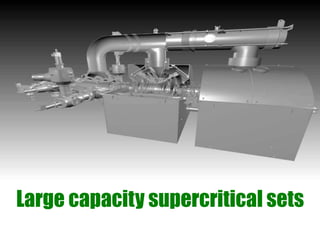
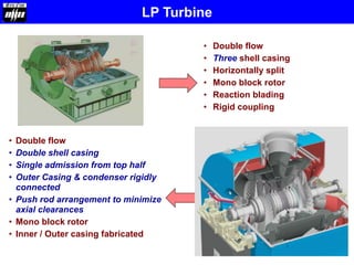
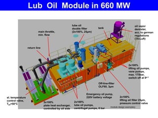
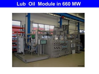
Large capacity supercritical sets
• Over all Efficiency can be improved by:
 Improving internal efficiency
 Adoption of advance steam parameters
Improving thermal efficiency
Improvement in efficiency with Increasing inlet
parameters for Steam turbines
Parameters for Critical State
• Steam Pressure > 221.2 Bar
• Steam Temperature > 374.15 Deg C
Ultra Supercritical Pressure  300 BAR
Increase in steam parameters results in significant improvement in efficiency
With higher cycle efficiency, the supercritical cycle offers lower emission &
lesser pollutants – SOX , NOX & CO2
0
5
10
15
20
25
30
35
40
45
500 MW 660 MW
Sub critical
170 ata / 537 °C / 537 °C
Super Critical
247 ata / 565 °C / 593 °C
Improvement
4.3 %
Entropy
Temperature
Supercritical Cycles
Details of Super-Critical Units in 10th , 11th , 12th &13th 5 Year Plans
Sub Critical
(MW)
660
MW
(No.)
800
MW
(No.)
Super Critical
(MW)
TOTAL
MW
10th Plan 9620 0 0 0 9620
11th Plan 45470 7 1 5420 50890
12th Plan 18270 25 33 42,900 61,170
13th Plan 4000 36 36 52,560 56,560
Power Projections
Comparison between SubCritical & SuperCritical (MW)
9620
45470
18270
4000
0
5420
42,900
52,560
0
10000
20000
30000
40000
50000
60000
10th Plan 11th Plan 12th Plan 13th Plan
Total Subcritical (MW) Total Super critical (MW)
Introduction of large capacity super critical
Steam Turbines with power output 660MW
HPT IPT LPT
Cross sectional arrangement of
500 mw Steam turbine
Cross sectional arrangement of
660 mw Steam turbine
Cross sectional arrangement of
800 mw Steam turbine
Module 500MW 660MW 800MW
HP Turbine H30-100 H30-100 (H70-V4) H30-100 (H70-V4)
IP Turbine M30-63 M30-63 (I50-V2) M30-100 (I60-V2)
LP Turbine N30-2x10 N30-2x12.5 (L2x12.5) N30-4x8 (L4x8)
HP Valves 2xFV320 2xFV250 2xFV250
IP Valves 2xAV560 2xAV560 2xAV560
Steam Turbine module configuration
PARAMETERS UNIT
SUBCRITICAL SUPERCRITICAL
500 MW 660 MW 800 MW
MS PRESSURE ATA 170 247 247
MS TEMPERATURE oC 537 565 565
MAIN STEAM FLOW T/HR 1500 2000 2425
REHEAT PRESSURE ATA 40.5 54 54
RH TEMPERATURE oC 537 593 593
REHEAT FLOW T/HR 1335 1740 2090
FINAL FEED WATER TEMP. oC 253 271 290
CONDENSATE FLOW T/HR 1180 1515 1860
Comparison of parameters
Overview of a Large capacity set with
super critical parameters
Constructional details of
HP turbine
Inner Casing
Inlet
Outer Casing-Barrel type
Exhaust
Shaft Seal-Front
Shaft Seal-Rear
• Single flow
• Double shell casing
– Inner casing axially split
– Outer casing barrel type &
axially divided
– Single exhaust in L/H
• Mono block rotor
• First stage diagonal blading
• Provision for extraction
• Over load valve
• Casing mounted valves
• Transported as single unit
• Single flow
• Double shell casing
– Inner casing : axially split
– Outer casing: Barrel type
– Single exhaust in L/H
• Mono block rotor
• Reaction blading with Integral
shroud
• Casing mounted valves
• Transported as single unit
HP Turbine
500 MW
660 MW
HP Turbine
HP Turbine
HP Turbine
For Over load valve
Extraction Chamber
Overload valve
HP Turbine
Section through HP admission with
sealing between HP inner and outer
shell
Section through HP admission
without sealing between HP inner
and outer shell
500 MW 660 MW
HP Turbine
HP Turbine Additional Features
Outer Casing (rear)
G17CrMo5-10
HW 19582
G-X12CrMoVNbN9-1
X22CrMoV12-1
HW 10687
Rotor
Inner Casing
HP Moving & Guide
Blades (rear) X12CrMoWVNbN10-1-1
HW19488
G-X12CrMoVNbN9-1
Outer Casing (front)
X12CrMoWVNbN10-1-1
HP Moving & Guide
Blades (front)
Materials of HP turbine
HP Turbine with Breech-Nut connection
Breech Nut
Constructional details of
IP turbine
• Double flow
• Double casing design with horizontal
split
• Inlet from Lower half
• Single Exhaust from upper half
• Extraction connections from lower
half
• Admission blade ring with cooling
Inner Casing
Inlet
Exhaust
Outer Casing
Extraction
Inlet
Rotor
• Double flow
• Double shell casing with horizontal
split
• Mono block rotor
• Reaction blading
• Inlet from Upper & Lower halves
• Two exhaust in L/H
• Extraction connections from Upper
& lower half
IP Turbine
Inlet
Exhaust
500 MW
660 MW
IP Turbine –Inlet Ring
•Reduction in wall temperature of
the Rotor
•Reduction in Creep damage
•Reduction of Cracking
•Increase of Life cycle time
IP Turbine –Inlet Ring
Outer Casing
GGG 40.3
HW 19793
G-X12CrMoVNbN9-1
Rotor
Inner Casing
X12CrMoWVNbN1011
HW19488
HW19688
Guide Blades:
X19CrMoVNbN111
IP Moving (initial stg.) :
NiCr20TiAl
Materials of IP turbine
Guide Blades:
X19CrMoVNbN111
IP Moving (rear stg.) :
NiCr20TiAl
IP Turbine with Casing mounted valves
Constructional details of
LP turbine
• Double flow
• Three shell casing
• Horizontally split
• Mono block rotor
• Reaction blading
• Rigid coupling
• Double flow
• Double shell casing
• Single admission from top half
• Outer Casing & condenser rigidly
connected
• Push rod arrangement to minimize
axial clearances
• Mono block rotor
• Inner / Outer casing fabricated
LP Turbine
LPT
LP Turbine - 500MW LP Turbine - 660 MW
LP Turbine
EXHAUST
DIFFUSER
ROTOR
LP INNER
INNER CASING
LP INNER OUTER
CASING
GUIDE BLADE
CARRIERS
LP LONGITUDINAL
GIRDER
LP FRONT WALL
ATMOSPHERIC RELIEF
DIAPHRAGM
LP Turbine - 500MW
LP Turbine – 660MW
EXHAUST
DIFFUSER
ROTOR
LP INNER OUTER
CASING
LP SIDE WALL
LP END WALL
ATMOSPHERIC RELIEF
DIAPHRAGM
CASING UPPER
PART
LP Turbine – 660MW
Arrangement of thrust bolt for minimizing
axial clearances
26NiCrMoV14-5
HW 19373
X20Cr13
HW 10786
Rotor
Inner Casing
LP Moving & Guide
Blades Drum Stages
X10CrNiMoV 12-2-2
HW 19392
Last Stage
Moving Blade
X2CrNi12
HW 18802
Hollow Guide
Blades
Fabricated
ST 37-II
AA10401/10119
Outer Casing
Materials for LP turbine
Fabricated
ST 37-II
AA10401/10119
Arrangement of thrust bolt for minimizing axial
clearances
Banana type guide blade
Last stages of LPT
Improved cylindrical profile blade (TX)
HPT / IPT middle & LPT initial stages
Twisted profile blade (F)
HPT / IPT rear stages
3 Dimensional blade (3 DS)
HPT / IPT initial stages
Turbine Blading
Fabricated bearing pedestals Cast bearing pedestals
GGG-40.3 Nodular Casting
Bearing Pedestals
Governing System
660 MW steam
turbine equipped
with high pressure
electro-hydraulic
governing system
Advantage:
• Compact design
• Less control fluid piping
• Less erection and commissioning
time
Characteristics 500 MW
(Low Pressure Gov.)
660 MW
(High Pressure Gov.)
Operating Pressure 8/32 Bar 160 Bar
IP valves Suspended Casing mounted
Control signal to
Actuator
Hydraulic Electronic
Size of Actuators Bulky Compact
Control & Protection
Elements
Hydraulic / Electro-
hydraulic
Electronic
Governing System
Advantages of high pressure EHA based governing system
• Bulky servomotors replaced with compact
actuators leading to compact layout in TG hall
• Governing & protection racks replaced by
electronic systems
• Faster response due to state of art electronic
control and protection systems
• Reduced manufacturing time at shop
• Turbine driven MOP replaced with motor driven
pump
• Mechanical Emergency governor replaced by
electronic protection system, eliminating actual
over speeding at site
Additional features
• Less noise because of latest features hence no
cleading up to 85 db
• Hydraulic turning wheel for barring replaced by
Hydraulic turning motor at front bearing pedestal
similar to 250 MW
• Steam strainer elements built in the valves resulting
in elimination of strainer housings
LP Bypass valve
Advantages:
1. Considerable reduction in overall space
2. Use of just one actuator, lower control fluid
consumption and simplified C&I. Small
sized HPSU
3. Overall weight of valve assembly will be
less
4. Less number of O&M Spares needed
5. Procurement and O&M cost will be much
less
In 500 MW LP Bypass, combined
stop & control valve is used
For 660 MW, single stem LP
Bypass valve having both stop
& control function will be used
Lub oil system in 500 MW set consists of
• Main Oil Tank
• Main Oil Pump (Turbine Driven)
• Auxiliary Oil Pump (2X100%)
• Emergency Oil Pump
• Jacking Oil Pump (2X100%)
• Oil Vapour Exhausters (2X100%)
• Oil Coolers (2X100%)
• Duplex Oil Filters (Lub Oil & Jacking Oil)
• Seal Oil Storage Tank
• Temp control valve, butterfly, pressure limit
valves
LUB OIL MODULE
el. temperature
control valve,
Toil=50°C
2x100%
lube oil pumps,
centrifugal pumps, 6 bar
Emergency oil pump,
220V battery voltage
2x100%
lifting oil pumps,
vane pumps,
max. 175bar,
switch off at 9s-1
oil vapor
demister,
acc. to german
regulations
(TA-Luft)
main throttle,
min. flow
lube oil
double filter
(2x100%, 25µm)
return line
2x100%
plate heat exchanger,
controlled by oil side
2x100%
lifting oil filter 25µm,
pressure control valve
tank
module design exemplary
Off-line-filter
OLF60, 3µm
Lub Oil Module in 660 MW
OIL MODULE
example
Lub Oil Module in 660 MW
• Turbine driven main oil pump in 500
MW set is replaced by motor driven
lub oil pump in 660 MW
Advantage:
1. Injectors in system are avoided
2. Interconnecting pipe between injectors &
MOP is no more required
3. Smaller main oil tank
Main Oil Pump
• Electric actuators of angle drain
valves replaced by pneumatic
actuators
Advantage:
In case of loss of control air, valves
move immediately in the defined fail
safe position.
A motorised valve remains in the actual
position in case of power loss and need
to be operated manually
Drain Valves
Steam Strainers
Steam strainers in 660
MW unit are located
inside turbine valves
(ESV & IV) and hence
separate strainer
housings in MS & HRH
lines are eliminated.
Thanks ……
STEAM TURBINE Unit 1 Unit 2
1 H. P. Turbine SAG SAG
2 I. P. Turbine SAG BHEL
3 L. P. Rotor SAG BHEL
4 L. P. Inner casing SAG BHEL
5 L. P. Outer casing BHEL BHEL
6 Cross Around Piping SAG BHEL
7 FB Pedestal SAG BHEL
8 HP Pedestal SAG BHEL
9 IP Pedestal SAG BHEL
10 LP Pedestal SAG BHEL
11 ESV & CV SAG BHEL
12 IVCV SAG BHEL
13 LPBP Valve BHEL BHEL
14 Governing Control Rack NA NA
15 LPBP Control Rack NA NA
16 Valves (CRH NRV, EXTRACTION NRVS,
OVERLOAD VALVES)
SAG BHEL
17 Instruments & Rack SAG SAG
18 Tools & Tackles SAG NA
19 TG Dec Embedments BHEL BHEL
20 Oil Module BHEL BHEL
21 Piping and Mounting Accessories (Turbine
Integral Piping System)
BHEL BHEL
25 Base Plate Assembly BHEL BHEL
800 MW TG SETS
660 MW BARH TG SETS
Division of Work
660 MW TG SETS
AVAILABILITY OF DOCUMENTS:
-The schedule given by Siemens indicates documents flow starting
Oct’ 2009 up to end of 2010.
-This does not suit BHEL
e.g. – LP outer casing is to be supplied by BHEL by February 2011
while Siemens’ date of supply of document is Oct’ 2010. Similar case
exists for other assemblies for set no.-2 (in BHEL scope).
- Preponment of 6-12 months required.
- Detailed letter being sent to Siemens by 10th July 2009.
- Documents for HP module shall be available from Siemens after
signing of TCAE3.
660 MW TG SETS
MANUFACTURING FACILITIES FOR TURBINES:
• Facility planned for weld overlay for HP / IP rotors.
• No other special facility is required for manufacture of these
turbines.
• Machining facilities had been evaluated on the basis of 660 MW
documentation received for Swarzpumpe project.
• Documentation for Barh project is yet to be received. It is envisaged
that being a modular design, major changes necessitating new
machines are not expected.

vdocument.in_660-mw-turbine.ppt

  • 1.
  • 2.
    • Over allEfficiency can be improved by:  Improving internal efficiency  Adoption of advance steam parameters Improving thermal efficiency
  • 3.
    Improvement in efficiencywith Increasing inlet parameters for Steam turbines
  • 4.
    Parameters for CriticalState • Steam Pressure > 221.2 Bar • Steam Temperature > 374.15 Deg C Ultra Supercritical Pressure  300 BAR Increase in steam parameters results in significant improvement in efficiency With higher cycle efficiency, the supercritical cycle offers lower emission & lesser pollutants – SOX , NOX & CO2 0 5 10 15 20 25 30 35 40 45 500 MW 660 MW Sub critical 170 ata / 537 °C / 537 °C Super Critical 247 ata / 565 °C / 593 °C Improvement 4.3 % Entropy Temperature Supercritical Cycles
  • 5.
    Details of Super-CriticalUnits in 10th , 11th , 12th &13th 5 Year Plans Sub Critical (MW) 660 MW (No.) 800 MW (No.) Super Critical (MW) TOTAL MW 10th Plan 9620 0 0 0 9620 11th Plan 45470 7 1 5420 50890 12th Plan 18270 25 33 42,900 61,170 13th Plan 4000 36 36 52,560 56,560 Power Projections Comparison between SubCritical & SuperCritical (MW) 9620 45470 18270 4000 0 5420 42,900 52,560 0 10000 20000 30000 40000 50000 60000 10th Plan 11th Plan 12th Plan 13th Plan Total Subcritical (MW) Total Super critical (MW)
  • 6.
    Introduction of largecapacity super critical Steam Turbines with power output 660MW
  • 7.
    HPT IPT LPT Crosssectional arrangement of 500 mw Steam turbine
  • 8.
    Cross sectional arrangementof 660 mw Steam turbine
  • 9.
    Cross sectional arrangementof 800 mw Steam turbine
  • 10.
    Module 500MW 660MW800MW HP Turbine H30-100 H30-100 (H70-V4) H30-100 (H70-V4) IP Turbine M30-63 M30-63 (I50-V2) M30-100 (I60-V2) LP Turbine N30-2x10 N30-2x12.5 (L2x12.5) N30-4x8 (L4x8) HP Valves 2xFV320 2xFV250 2xFV250 IP Valves 2xAV560 2xAV560 2xAV560 Steam Turbine module configuration
  • 11.
    PARAMETERS UNIT SUBCRITICAL SUPERCRITICAL 500MW 660 MW 800 MW MS PRESSURE ATA 170 247 247 MS TEMPERATURE oC 537 565 565 MAIN STEAM FLOW T/HR 1500 2000 2425 REHEAT PRESSURE ATA 40.5 54 54 RH TEMPERATURE oC 537 593 593 REHEAT FLOW T/HR 1335 1740 2090 FINAL FEED WATER TEMP. oC 253 271 290 CONDENSATE FLOW T/HR 1180 1515 1860 Comparison of parameters
  • 12.
    Overview of aLarge capacity set with super critical parameters
  • 13.
  • 14.
    Inner Casing Inlet Outer Casing-Barreltype Exhaust Shaft Seal-Front Shaft Seal-Rear • Single flow • Double shell casing – Inner casing axially split – Outer casing barrel type & axially divided – Single exhaust in L/H • Mono block rotor • First stage diagonal blading • Provision for extraction • Over load valve • Casing mounted valves • Transported as single unit • Single flow • Double shell casing – Inner casing : axially split – Outer casing: Barrel type – Single exhaust in L/H • Mono block rotor • Reaction blading with Integral shroud • Casing mounted valves • Transported as single unit HP Turbine 500 MW 660 MW
  • 15.
  • 16.
  • 17.
    HP Turbine For Overload valve Extraction Chamber
  • 18.
  • 19.
  • 20.
    Section through HPadmission with sealing between HP inner and outer shell Section through HP admission without sealing between HP inner and outer shell 500 MW 660 MW HP Turbine
  • 21.
  • 22.
    Outer Casing (rear) G17CrMo5-10 HW19582 G-X12CrMoVNbN9-1 X22CrMoV12-1 HW 10687 Rotor Inner Casing HP Moving & Guide Blades (rear) X12CrMoWVNbN10-1-1 HW19488 G-X12CrMoVNbN9-1 Outer Casing (front) X12CrMoWVNbN10-1-1 HP Moving & Guide Blades (front) Materials of HP turbine
  • 23.
    HP Turbine withBreech-Nut connection Breech Nut
  • 24.
  • 25.
    • Double flow •Double casing design with horizontal split • Inlet from Lower half • Single Exhaust from upper half • Extraction connections from lower half • Admission blade ring with cooling Inner Casing Inlet Exhaust Outer Casing Extraction Inlet Rotor • Double flow • Double shell casing with horizontal split • Mono block rotor • Reaction blading • Inlet from Upper & Lower halves • Two exhaust in L/H • Extraction connections from Upper & lower half IP Turbine Inlet Exhaust 500 MW 660 MW
  • 26.
  • 27.
    •Reduction in walltemperature of the Rotor •Reduction in Creep damage •Reduction of Cracking •Increase of Life cycle time IP Turbine –Inlet Ring
  • 28.
    Outer Casing GGG 40.3 HW19793 G-X12CrMoVNbN9-1 Rotor Inner Casing X12CrMoWVNbN1011 HW19488 HW19688 Guide Blades: X19CrMoVNbN111 IP Moving (initial stg.) : NiCr20TiAl Materials of IP turbine Guide Blades: X19CrMoVNbN111 IP Moving (rear stg.) : NiCr20TiAl
  • 29.
    IP Turbine withCasing mounted valves
  • 30.
  • 31.
    • Double flow •Three shell casing • Horizontally split • Mono block rotor • Reaction blading • Rigid coupling • Double flow • Double shell casing • Single admission from top half • Outer Casing & condenser rigidly connected • Push rod arrangement to minimize axial clearances • Mono block rotor • Inner / Outer casing fabricated LP Turbine
  • 32.
    LPT LP Turbine -500MW LP Turbine - 660 MW LP Turbine
  • 33.
    EXHAUST DIFFUSER ROTOR LP INNER INNER CASING LPINNER OUTER CASING GUIDE BLADE CARRIERS LP LONGITUDINAL GIRDER LP FRONT WALL ATMOSPHERIC RELIEF DIAPHRAGM LP Turbine - 500MW
  • 34.
    LP Turbine –660MW EXHAUST DIFFUSER ROTOR LP INNER OUTER CASING LP SIDE WALL LP END WALL ATMOSPHERIC RELIEF DIAPHRAGM CASING UPPER PART
  • 35.
  • 36.
    Arrangement of thrustbolt for minimizing axial clearances
  • 37.
    26NiCrMoV14-5 HW 19373 X20Cr13 HW 10786 Rotor InnerCasing LP Moving & Guide Blades Drum Stages X10CrNiMoV 12-2-2 HW 19392 Last Stage Moving Blade X2CrNi12 HW 18802 Hollow Guide Blades Fabricated ST 37-II AA10401/10119 Outer Casing Materials for LP turbine Fabricated ST 37-II AA10401/10119
  • 38.
    Arrangement of thrustbolt for minimizing axial clearances
  • 39.
    Banana type guideblade Last stages of LPT Improved cylindrical profile blade (TX) HPT / IPT middle & LPT initial stages Twisted profile blade (F) HPT / IPT rear stages 3 Dimensional blade (3 DS) HPT / IPT initial stages Turbine Blading
  • 40.
    Fabricated bearing pedestalsCast bearing pedestals GGG-40.3 Nodular Casting Bearing Pedestals
  • 41.
    Governing System 660 MWsteam turbine equipped with high pressure electro-hydraulic governing system Advantage: • Compact design • Less control fluid piping • Less erection and commissioning time
  • 42.
    Characteristics 500 MW (LowPressure Gov.) 660 MW (High Pressure Gov.) Operating Pressure 8/32 Bar 160 Bar IP valves Suspended Casing mounted Control signal to Actuator Hydraulic Electronic Size of Actuators Bulky Compact Control & Protection Elements Hydraulic / Electro- hydraulic Electronic Governing System
  • 43.
    Advantages of highpressure EHA based governing system • Bulky servomotors replaced with compact actuators leading to compact layout in TG hall • Governing & protection racks replaced by electronic systems • Faster response due to state of art electronic control and protection systems • Reduced manufacturing time at shop • Turbine driven MOP replaced with motor driven pump • Mechanical Emergency governor replaced by electronic protection system, eliminating actual over speeding at site
  • 44.
    Additional features • Lessnoise because of latest features hence no cleading up to 85 db • Hydraulic turning wheel for barring replaced by Hydraulic turning motor at front bearing pedestal similar to 250 MW • Steam strainer elements built in the valves resulting in elimination of strainer housings
  • 45.
    LP Bypass valve Advantages: 1.Considerable reduction in overall space 2. Use of just one actuator, lower control fluid consumption and simplified C&I. Small sized HPSU 3. Overall weight of valve assembly will be less 4. Less number of O&M Spares needed 5. Procurement and O&M cost will be much less In 500 MW LP Bypass, combined stop & control valve is used For 660 MW, single stem LP Bypass valve having both stop & control function will be used
  • 46.
    Lub oil systemin 500 MW set consists of • Main Oil Tank • Main Oil Pump (Turbine Driven) • Auxiliary Oil Pump (2X100%) • Emergency Oil Pump • Jacking Oil Pump (2X100%) • Oil Vapour Exhausters (2X100%) • Oil Coolers (2X100%) • Duplex Oil Filters (Lub Oil & Jacking Oil) • Seal Oil Storage Tank • Temp control valve, butterfly, pressure limit valves
  • 47.
    LUB OIL MODULE el.temperature control valve, Toil=50°C 2x100% lube oil pumps, centrifugal pumps, 6 bar Emergency oil pump, 220V battery voltage 2x100% lifting oil pumps, vane pumps, max. 175bar, switch off at 9s-1 oil vapor demister, acc. to german regulations (TA-Luft) main throttle, min. flow lube oil double filter (2x100%, 25µm) return line 2x100% plate heat exchanger, controlled by oil side 2x100% lifting oil filter 25µm, pressure control valve tank module design exemplary Off-line-filter OLF60, 3µm Lub Oil Module in 660 MW
  • 48.
  • 49.
    • Turbine drivenmain oil pump in 500 MW set is replaced by motor driven lub oil pump in 660 MW Advantage: 1. Injectors in system are avoided 2. Interconnecting pipe between injectors & MOP is no more required 3. Smaller main oil tank Main Oil Pump
  • 50.
    • Electric actuatorsof angle drain valves replaced by pneumatic actuators Advantage: In case of loss of control air, valves move immediately in the defined fail safe position. A motorised valve remains in the actual position in case of power loss and need to be operated manually Drain Valves
  • 51.
    Steam Strainers Steam strainersin 660 MW unit are located inside turbine valves (ESV & IV) and hence separate strainer housings in MS & HRH lines are eliminated.
  • 52.
  • 53.
    STEAM TURBINE Unit1 Unit 2 1 H. P. Turbine SAG SAG 2 I. P. Turbine SAG BHEL 3 L. P. Rotor SAG BHEL 4 L. P. Inner casing SAG BHEL 5 L. P. Outer casing BHEL BHEL 6 Cross Around Piping SAG BHEL 7 FB Pedestal SAG BHEL 8 HP Pedestal SAG BHEL 9 IP Pedestal SAG BHEL 10 LP Pedestal SAG BHEL 11 ESV & CV SAG BHEL 12 IVCV SAG BHEL 13 LPBP Valve BHEL BHEL 14 Governing Control Rack NA NA 15 LPBP Control Rack NA NA 16 Valves (CRH NRV, EXTRACTION NRVS, OVERLOAD VALVES) SAG BHEL 17 Instruments & Rack SAG SAG 18 Tools & Tackles SAG NA 19 TG Dec Embedments BHEL BHEL 20 Oil Module BHEL BHEL 21 Piping and Mounting Accessories (Turbine Integral Piping System) BHEL BHEL 25 Base Plate Assembly BHEL BHEL 800 MW TG SETS 660 MW BARH TG SETS Division of Work
  • 54.
    660 MW TGSETS AVAILABILITY OF DOCUMENTS: -The schedule given by Siemens indicates documents flow starting Oct’ 2009 up to end of 2010. -This does not suit BHEL e.g. – LP outer casing is to be supplied by BHEL by February 2011 while Siemens’ date of supply of document is Oct’ 2010. Similar case exists for other assemblies for set no.-2 (in BHEL scope). - Preponment of 6-12 months required. - Detailed letter being sent to Siemens by 10th July 2009. - Documents for HP module shall be available from Siemens after signing of TCAE3.
  • 55.
    660 MW TGSETS MANUFACTURING FACILITIES FOR TURBINES: • Facility planned for weld overlay for HP / IP rotors. • No other special facility is required for manufacture of these turbines. • Machining facilities had been evaluated on the basis of 660 MW documentation received for Swarzpumpe project. • Documentation for Barh project is yet to be received. It is envisaged that being a modular design, major changes necessitating new machines are not expected.