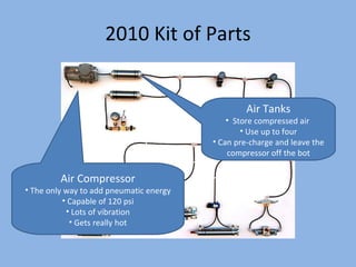
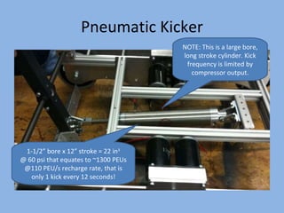
Pneumatics for FIRST Robots FIRSTFare 2010 Craig Boezwinkle Mechanical Engineer – Western Integrated Technologies Team 2811 Mentor (Skyview HS, Vancouver WA)
Overview Intro Kit of Parts Overview Cylinder sizing calculations System sizing calculations Typical applications on your robot Pros and Cons
Pneumatics 101 “the use of a pressurized gas to create mechanical motion” Everyday Uses: Air compressor to fill your tires “ Shop air” in industrial shops Air-operated hand tools Air-operated paint sprayers Pneumatic systems for industry Packaging lines Blow molding The list goes on, pneumatics are everywhere
Electrical Analogy Pressure = Voltage Volume = Capacitance Flow rate = Current Flow Restrictions = Resistance HOWEVER : Air is compressible => Some unique non-linearities when compared to electrical systems
2010 Kit of Parts Air Compressor The only way to add pneumatic energy Capable of 120 psi Lots of vibration Gets really hot Air Tanks Store compressed air  Use up to four Can pre-charge and leave the compressor off the bot
2010 Kit of Parts Required Equipment Pressure gauge – indicates pressure in compressor and tanks (not pressure at cylinders) Pressure switch – talks to cRIO Plug valve – releases all air in the system
2010 Kit of Parts Norgren Regulator Primary pressure regulator Reducing/relieving valve Limits all pressure downstream to 60 psi max Monnier Regulator Note yellow ring Secondary pressure regulator Allows for a reduced pressure leg, if desired
2010 Kit of Parts Solenoid Valves Control cylinder movement Come in either single solenoid or dual solenoid Control the flow of air to and from an actuator Cylinders aka NOT PISTONS Not supplied with KOP Custom order up to three FREE Design first, order second
Rules Know them.  Look in these three places: Standalone pneumatics manual Pneumatics section of rules Inspection checklist 125psi relief attached directly to compressor Must include easily accessible vent valve Special label required for pressure release valve Gauges required on both stored and working pressure sides of system Etc, etc, etc.  Don’t learn these for the first time during inspection.
Calculating Force 60 psi 106 lbs To  extend  the cylinder, pressurize the  cap  end port. Force (lbs) = Pressure (psi) x Area (in 2 ) Area =   r 2  =    * (0.75 in)  2  = 1.77 in 2 Force = ( 60 lb / in 2  ) * ( 1.77 in 2  ) Force = 106.2 lbs NOTE: Single acting cylinders are only powered in one direction.  They require an external force to move in the other direction (spring retract, load pushing back, etc).  Double acting cylinders are powered in both directions. 1-1/2 ” bore
Calculating Force 60 psi To  retract  the cylinder, pressurize the  rod  end port. Force (lbs) = Pressure (psi) x Area (in 2 ) NOTE: The area on the rod end is always less than the area on the cap end. Effective Rod End Area = Cap Area – Area of the Rod Cap Area =   r 2  =    * (0.75 in)  2  = 1.77 in 2 Rod Area =   r 2  =    * (0.21875 in)  2  = 0.150 in 2 Effective Area = 1.77 in – 0.150 in = 1.62 in 2 Force = ( 60 lb / in 2  ) * ( 1.62 in 2  ) Force = 97.2 lbs 1-1/2 ” bore 97 lbs 7/16 ” rod diameter
This is a good spot to mention, … Safety Respect the amount of power that a pneumatic system can generate Understand the rules and abide by them even during practice and test (they rules exist for a reason – to keep everyone safe) A 2” bore cylinder @ 120psi = 376 lb-force (don’t do this!, it can cause injury or bend the frame of your robot)
Did you notice… Amount of force has nothing to do with cylinder length (stroke).  Only pressure and cylinder area (bore) matter. However Amount of air volume required has EVERYTHING to do with cylinder length (stroke)
System Sizing Notes Both system pressure and volume are limited quantities Therefore, we have a fixed amount of energy that can be stored and used To simplify things, we ’ll introduce a unit of measure call the PEU (pneumatic energy unit) PEUs = Pressure x Volume Boyle ’s Law Says Pressure * Volume = constant
Energy Usage Example Energy Storage Energy Consumption Load Credit: Raul Olivera Storage Consumption PEUs P V P V PEUs Total PEUs 2400.0 120.0 20.0 60.0 10.0 600.0 3000.0 1800.0 90.0 20.0 60.0 10.0 600.0 2400.0 1200.0 60.0 20.0 60.0 10.0 600.0 1800.0 800.0 40.0 20.0 40.0 10.0 400.0 1200.0 533.3 26.7 20.0 26.7 10.0 266.7 800.0 355.6 17.8 20.0 17.8 10.0 177.8 533.3
Replacing Used Energy Used energy can be replenished by the compressor, but how fast? Previous compressor could replace about 110 PEU/s in the cut out range (90 to 120 psig) Your mileage may vary – run your own tests! Credit: Raul Olivera
Managing the Loss of Energy Use only the amount of energy required, not too much more Minimize Volume: tubing length (valve to cylinder) cylinder stroke cylinder diameter Minimize regulated pressure But, keep above valve pilot pressure requirement
Typical Applications Two-position linear applications Lifter or gate Transmission shifter Linear pneumatic gripper Braking systems Lots of 2010 kickers Latch release mechanisms
Example: Transmission Shifter Toggles between two different gear ratios Low gear = power High gear = speed Standard add-on for AndyMark Super Shifter Or design your own! ¾ ” bore x ½” stroke cylinder – can easily be used without compressor
Example: Linear Pneumatic Gripper NOTE: The solenoid valve is installed close to the cylinder. This minimizes wasted energy.
Example: Linear Pneumatic Gripper
Example: 1-axis and 2-axis Grippers
Example: Pneumatic Brakes Extend cylinder to stop a manipulator, or use on wheels to lock your drivetrain Use normally open solenoid if you want the brake applied with no electricity Low energy requirements – can easily be used without compressor
Winch-Wound Kicker, Pneumatic Release
Pneumatic Kicker NOTE: This is a large bore, long stroke cylinder. Kick frequency is limited by compressor output. 1-1/2” bore x 12” stroke = 22 in 3 @ 60 psi that equates to ~1300 PEUs @110 PEU/s recharge rate, that is only 1 kick every 12 seconds!
The Good and Bad Good At Fast movement: kickers, shifters, pin pullers, at times equivalent to a solenoid (solenoids illegal) Two-position mechanisms: fully extended, fully retracted Sustained Holding: clamp, grabbers (motors would burn up) Unpowered mechanisms: for end of match bonus (avoid leaks!) Bad At Rotational movement > 180 deg (cylinders are linear) Sustained movement (you’ll run out of air) Accurate position control: middle of stroke = gray area
Less specifically… PROs Doesn ’t overheat Designed to stall High speed Accurate end of stroke position control Can hold without battery power CONs Heavy (10 lbs+) Battery drain Space Limited control
General Suggestions Order your free cylinders even if you don ’t use pneumatics this year Because of weight and space requirements, look to pneumatics if you have 2+ uses (unless you can leave off the compressor) Do not tolerate leaks Conserve energy – don ’t oversize or over-pressurize
General Suggestions Know the rules Soapy water (goggles cleaner?) makes for a good leak detector Properly apply Teflon tape (more != better) Cut all tubing at 90 degrees to the tube axis Tighten + mark all fittings Have a system schematic / diagram
Questions? Thanks to: Raul Olivera http://first.wpi.edu/Images/CMS/First/2007CON_Pneumatic_Power_Olivera.pdf Andy Baker http://andymark.biz/presentations.html Ken Stafford http://first.wpi.edu/Images/CMS/First/2008FRC_Pneumatics_Stafford.ppt Chief Delphi http://www.chiefdelphi.com / Official FIRST Pneumatics Manual http://usfirst.org/uploadedFiles/Community/FRC/Game_and_Season__Info/2010_Assets/2010%20Pneumatics%20Manual%20Rev%20-.pdf

First fare 2010 pneumatics presentation

  • 1.
    Pneumatics for FIRSTRobots FIRSTFare 2010 Craig Boezwinkle Mechanical Engineer – Western Integrated Technologies Team 2811 Mentor (Skyview HS, Vancouver WA)
  • 2.
    Overview Intro Kitof Parts Overview Cylinder sizing calculations System sizing calculations Typical applications on your robot Pros and Cons
  • 3.
    Pneumatics 101 “theuse of a pressurized gas to create mechanical motion” Everyday Uses: Air compressor to fill your tires “ Shop air” in industrial shops Air-operated hand tools Air-operated paint sprayers Pneumatic systems for industry Packaging lines Blow molding The list goes on, pneumatics are everywhere
  • 4.
    Electrical Analogy Pressure= Voltage Volume = Capacitance Flow rate = Current Flow Restrictions = Resistance HOWEVER : Air is compressible => Some unique non-linearities when compared to electrical systems
  • 5.
    2010 Kit ofParts Air Compressor The only way to add pneumatic energy Capable of 120 psi Lots of vibration Gets really hot Air Tanks Store compressed air Use up to four Can pre-charge and leave the compressor off the bot
  • 6.
    2010 Kit ofParts Required Equipment Pressure gauge – indicates pressure in compressor and tanks (not pressure at cylinders) Pressure switch – talks to cRIO Plug valve – releases all air in the system
  • 7.
    2010 Kit ofParts Norgren Regulator Primary pressure regulator Reducing/relieving valve Limits all pressure downstream to 60 psi max Monnier Regulator Note yellow ring Secondary pressure regulator Allows for a reduced pressure leg, if desired
  • 8.
    2010 Kit ofParts Solenoid Valves Control cylinder movement Come in either single solenoid or dual solenoid Control the flow of air to and from an actuator Cylinders aka NOT PISTONS Not supplied with KOP Custom order up to three FREE Design first, order second
  • 9.
    Rules Know them. Look in these three places: Standalone pneumatics manual Pneumatics section of rules Inspection checklist 125psi relief attached directly to compressor Must include easily accessible vent valve Special label required for pressure release valve Gauges required on both stored and working pressure sides of system Etc, etc, etc. Don’t learn these for the first time during inspection.
  • 10.
    Calculating Force 60psi 106 lbs To extend the cylinder, pressurize the cap end port. Force (lbs) = Pressure (psi) x Area (in 2 ) Area =  r 2 =  * (0.75 in) 2 = 1.77 in 2 Force = ( 60 lb / in 2 ) * ( 1.77 in 2 ) Force = 106.2 lbs NOTE: Single acting cylinders are only powered in one direction. They require an external force to move in the other direction (spring retract, load pushing back, etc). Double acting cylinders are powered in both directions. 1-1/2 ” bore
  • 11.
    Calculating Force 60psi To retract the cylinder, pressurize the rod end port. Force (lbs) = Pressure (psi) x Area (in 2 ) NOTE: The area on the rod end is always less than the area on the cap end. Effective Rod End Area = Cap Area – Area of the Rod Cap Area =  r 2 =  * (0.75 in) 2 = 1.77 in 2 Rod Area =  r 2 =  * (0.21875 in) 2 = 0.150 in 2 Effective Area = 1.77 in – 0.150 in = 1.62 in 2 Force = ( 60 lb / in 2 ) * ( 1.62 in 2 ) Force = 97.2 lbs 1-1/2 ” bore 97 lbs 7/16 ” rod diameter
  • 12.
    This is agood spot to mention, … Safety Respect the amount of power that a pneumatic system can generate Understand the rules and abide by them even during practice and test (they rules exist for a reason – to keep everyone safe) A 2” bore cylinder @ 120psi = 376 lb-force (don’t do this!, it can cause injury or bend the frame of your robot)
  • 13.
    Did you notice…Amount of force has nothing to do with cylinder length (stroke). Only pressure and cylinder area (bore) matter. However Amount of air volume required has EVERYTHING to do with cylinder length (stroke)
  • 14.
    System Sizing NotesBoth system pressure and volume are limited quantities Therefore, we have a fixed amount of energy that can be stored and used To simplify things, we ’ll introduce a unit of measure call the PEU (pneumatic energy unit) PEUs = Pressure x Volume Boyle ’s Law Says Pressure * Volume = constant
  • 15.
    Energy Usage ExampleEnergy Storage Energy Consumption Load Credit: Raul Olivera Storage Consumption PEUs P V P V PEUs Total PEUs 2400.0 120.0 20.0 60.0 10.0 600.0 3000.0 1800.0 90.0 20.0 60.0 10.0 600.0 2400.0 1200.0 60.0 20.0 60.0 10.0 600.0 1800.0 800.0 40.0 20.0 40.0 10.0 400.0 1200.0 533.3 26.7 20.0 26.7 10.0 266.7 800.0 355.6 17.8 20.0 17.8 10.0 177.8 533.3
  • 16.
    Replacing Used EnergyUsed energy can be replenished by the compressor, but how fast? Previous compressor could replace about 110 PEU/s in the cut out range (90 to 120 psig) Your mileage may vary – run your own tests! Credit: Raul Olivera
  • 17.
    Managing the Lossof Energy Use only the amount of energy required, not too much more Minimize Volume: tubing length (valve to cylinder) cylinder stroke cylinder diameter Minimize regulated pressure But, keep above valve pilot pressure requirement
  • 18.
    Typical Applications Two-positionlinear applications Lifter or gate Transmission shifter Linear pneumatic gripper Braking systems Lots of 2010 kickers Latch release mechanisms
  • 19.
    Example: Transmission ShifterToggles between two different gear ratios Low gear = power High gear = speed Standard add-on for AndyMark Super Shifter Or design your own! ¾ ” bore x ½” stroke cylinder – can easily be used without compressor
  • 20.
    Example: Linear PneumaticGripper NOTE: The solenoid valve is installed close to the cylinder. This minimizes wasted energy.
  • 21.
  • 22.
    Example: 1-axis and2-axis Grippers
  • 23.
    Example: Pneumatic BrakesExtend cylinder to stop a manipulator, or use on wheels to lock your drivetrain Use normally open solenoid if you want the brake applied with no electricity Low energy requirements – can easily be used without compressor
  • 24.
  • 25.
    Pneumatic Kicker NOTE:This is a large bore, long stroke cylinder. Kick frequency is limited by compressor output. 1-1/2” bore x 12” stroke = 22 in 3 @ 60 psi that equates to ~1300 PEUs @110 PEU/s recharge rate, that is only 1 kick every 12 seconds!
  • 26.
    The Good andBad Good At Fast movement: kickers, shifters, pin pullers, at times equivalent to a solenoid (solenoids illegal) Two-position mechanisms: fully extended, fully retracted Sustained Holding: clamp, grabbers (motors would burn up) Unpowered mechanisms: for end of match bonus (avoid leaks!) Bad At Rotational movement > 180 deg (cylinders are linear) Sustained movement (you’ll run out of air) Accurate position control: middle of stroke = gray area
  • 27.
    Less specifically… PROsDoesn ’t overheat Designed to stall High speed Accurate end of stroke position control Can hold without battery power CONs Heavy (10 lbs+) Battery drain Space Limited control
  • 28.
    General Suggestions Orderyour free cylinders even if you don ’t use pneumatics this year Because of weight and space requirements, look to pneumatics if you have 2+ uses (unless you can leave off the compressor) Do not tolerate leaks Conserve energy – don ’t oversize or over-pressurize
  • 29.
    General Suggestions Knowthe rules Soapy water (goggles cleaner?) makes for a good leak detector Properly apply Teflon tape (more != better) Cut all tubing at 90 degrees to the tube axis Tighten + mark all fittings Have a system schematic / diagram
  • 30.
    Questions? Thanks to:Raul Olivera http://first.wpi.edu/Images/CMS/First/2007CON_Pneumatic_Power_Olivera.pdf Andy Baker http://andymark.biz/presentations.html Ken Stafford http://first.wpi.edu/Images/CMS/First/2008FRC_Pneumatics_Stafford.ppt Chief Delphi http://www.chiefdelphi.com / Official FIRST Pneumatics Manual http://usfirst.org/uploadedFiles/Community/FRC/Game_and_Season__Info/2010_Assets/2010%20Pneumatics%20Manual%20Rev%20-.pdf