Downloaded 133 times
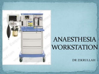


An anesthesia workstation integrates components for anesthesia administration into one unit. It consists of an anesthesia machine, vaporizers, ventilator, breathing system, scavenging system, and monitors. Key components include the gas supply system, which receives gases from cylinders and pipelines and regulates pressures, and the vaporizer manifold and anesthetic vaporizers. Modern workstations have additional safety features to prevent delivery of hypoxic gas mixtures and other hazards.


![ANESTHESIA_MACHINE-_PRESSURE_REDUCING_VALVES,_FLOWMETER_AND[1].pptx](https://cdn.slidesharecdn.com/ss_thumbnails/anesthesiamachine-pressurereducingvalvesflowmeterand1-250127121142-c2585726-thumbnail.jpg?width=640&height=640&fit=bounds)


