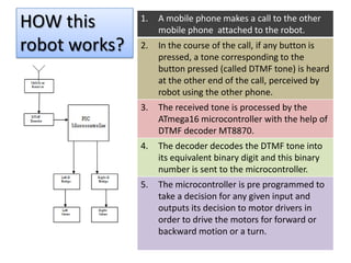
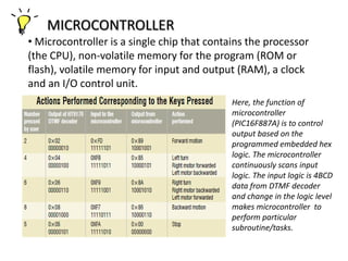
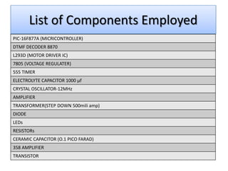
HINDUSTAN INSTITUTE OF TECHNOLOGY
                   GR. NOIDA


                    MAJOR PROJECT
                                                 EEC - 851


Presented by :
Akash Chandel    Anupam Singh   Ashutosh Singh   Nishi Kant Rai
(0821331024)     (0821331028)   (0821331024)     (08213------)
CELLPHONE
 OPERATED
LAND ROVER
CONTENTS OF THE PRESENTATION

• SECTION A: PROJECT OVERVIEW
   PART 1 : WHAT this project is all about
   PART 2: HOW this project/robot works
   PART 3: WHERE this robot can be used

• SECTION B: TECHNICAL ASPECTS
   PART 1: List of Components employed
   PART 2: Circuit and Pin Diagram

• SECTION C: CONCLUSION
Section A :

PROJECT OVERVIEW
WHAT this robot actually does?
• Today, cell phone has displaced nearly all the
  old traditional devices of communication.
• So, in this project we show that how we can
  control the movement of any small robot with
  the help of mobile phone.
• And hence, by using this logic we can not only
  control the movement of vehicle but also
  switch on/off other accessories on robot.
• The movement is controlled by pressing
relevant keys on a mobile phone that
makes a call to another mobile phone
attached to the robot.
HOW this       1.   A mobile phone makes a call to the other
                    mobile phone attached to the robot.
robot works?   2.   In the course of the call, if any button is
                    pressed, a tone corresponding to the
                    button pressed (called DTMF tone) is heard
                    at the other end of the call, perceived by
                    robot using the other phone.
               3.   The received tone is processed by the
                    ATmega16 microcontroller with the help of
                    DTMF decoder MT8870.
               4.   The decoder decodes the DTMF tone into
                    its equivalent binary digit and this binary
                    number is sent to the microcontroller.
               5.   The microcontroller is pre programmed to
                    take a decision for any given input and
                    outputs its decision to motor drivers in
                    order to drive the motors for forward or
                    backward motion or a turn.
DTMF: Dual Tone Multi Frequency
• DTMF signalling is used for telephone signalling over the line in
the voice-frequency band to the call switching centre. The
version of DTMF used for telephone tone dialling is known as
‘Touch-Tone.’
• DTMF assigns a specific frequency (consisting of two separate
tones) to each key so that it can easily be identified by the
electronic circuit.
                                 The DTMF keypad is laid out in a 4×4
                                matrix, with each row representing
                                a low frequency, and each column
                                representing a high frequency. Pressing
                                a single key (such as '1' ) will send
                                a sinusoidal tone for each of the two
                                frequencies (697 and 1209 Hz).
DTMF Decoder
                        • A DTMF Decoder takes in DTMF
    D3   D2   D1   D0
                        tone and converts it into BCD
1   0    0    0    1    code, output depending upon
2   0    0    1    0    which key is pressed at the
3   0    0    1    1    transmitter side.
4   0    1    0    0
                        • A number of companies make
5   0    1    0    1
                        chips which decode these DTMF
6   0    1    1    0
                        signal. One such IC is HT 9170.
7   0    1    1    1
8   1    0    0    0    • The device after detecting a valid
9   1    0    0    1    tone-pair makes one of the pins
*   1    0    1    0
                        high (StD) for a short duration and
                        the output latch is updated (D0-D3)
0   1    0    1    1
                        according to the received tone-pair
#   1    1    0    0
H BRIDGE Concept for motor driver
                 • An H bridge is an electronic
                 circuit that enables a voltage to be
                 applied across a load in either
                 direction by turning S1-S4 On/Off.

                 • These circuits are often used
                 in robotics and other applications
                 to allow DC motors to run forwards
                 and backwards.

                 •H bridges are available as
                 integrated circuits(here L298), or
                 can be built from discrete
                 components.
MICROCONTROLLER
• Microcontroller is a single chip that contains the processor
(the CPU), non-volatile memory for the program (ROM or
flash), volatile memory for input and output (RAM), a clock
and an I/O control unit.
                                             Here, the function of
                                             microcontroller
                                             (PIC16F887A) is to control
                                             output based on the
                                             programmed embedded hex
                                             logic. The microcontroller
                                             continuously scans input
                                             logic. The input logic is 4BCD
                                             data from DTMF decoder
                                             and change in the logic level
                                             makes microcontroller to
                                             perform particular
                                             subroutine/tasks.
WHERE this robot can be used?
• Agriculture and farming :
  “Remote-controlled robot uses thermal imaging to detect and
  eradicate termites” – Gizmag
  The Termibot carries video and thermal imaging cameras where human
  pest controllers can't go. When a telltale heat or moisture signature is
  detected, Termicam breaks termite nests open to confirm the
  infestation, then pumps pest control chemicals directly into the source.
• Military and security operations:
  “Had there been a high range, light weight robot which could
  go into the hotels where terrorists held guests hostage during
  the 26/11 attack and send the images from inside, the security
  forces could have perhaps handled the situation better and
  the casualties would have been limited.”

  “ This concept is taken from military application where such
  land rover works as Unmanned Guided vehicle (UGV) for spy
  operations, mine diffuser, bomb detector etc. in such
  application the movements of land rover can be controlled
  from very far remote and safe place (as there is practically no
  limitation on operating range)”
Section B :

TECHNICAL ASPECTS
List of Components Employed
PIC-16F877A (MICRICONTROLLER)
DTMF DECODER 8870
L293D (MOTOR DRIVER IC)
7805 (VOLTAGE REGULATER)
555 TIMER
ELECTROLYTE CAPACITOR 1000 µf
CRYSTAL OSCILLATOR-12MHz
AMPLIFIER
TRANSFORMER(STEP DOWN 500mili amp)
DIODE
LEDs
RESISTORs
CERAMIC CAPACITOR (O.1 PICO FARAD)
358 AMPLIFIER
TRANSISTOR
CIRCUIT DIAGRAM
Section C :

CONCLUSION
• Scope for learning :
   PCB designing and various steps involved.
   PIC Microcontroller and its interfacing
   Programming the microcontroller using C

• Scope for improvement :
   This land rover can be further improved to
  serve specific purposes. It requires four
  controls to roam around. The remaining eight
  controls can be configured to serve other
  purposes, with some modifications in the
  source program of the microcontroller.
Ppt land rover

Ppt land rover

  • 1.
    HINDUSTAN INSTITUTE OFTECHNOLOGY GR. NOIDA MAJOR PROJECT EEC - 851 Presented by : Akash Chandel Anupam Singh Ashutosh Singh Nishi Kant Rai (0821331024) (0821331028) (0821331024) (08213------)
  • 2.
  • 3.
    CONTENTS OF THEPRESENTATION • SECTION A: PROJECT OVERVIEW  PART 1 : WHAT this project is all about  PART 2: HOW this project/robot works  PART 3: WHERE this robot can be used • SECTION B: TECHNICAL ASPECTS  PART 1: List of Components employed  PART 2: Circuit and Pin Diagram • SECTION C: CONCLUSION
  • 4.
  • 5.
    WHAT this robotactually does? • Today, cell phone has displaced nearly all the old traditional devices of communication. • So, in this project we show that how we can control the movement of any small robot with the help of mobile phone. • And hence, by using this logic we can not only control the movement of vehicle but also switch on/off other accessories on robot.
  • 6.
    • The movementis controlled by pressing relevant keys on a mobile phone that makes a call to another mobile phone attached to the robot.
  • 7.
    HOW this 1. A mobile phone makes a call to the other mobile phone attached to the robot. robot works? 2. In the course of the call, if any button is pressed, a tone corresponding to the button pressed (called DTMF tone) is heard at the other end of the call, perceived by robot using the other phone. 3. The received tone is processed by the ATmega16 microcontroller with the help of DTMF decoder MT8870. 4. The decoder decodes the DTMF tone into its equivalent binary digit and this binary number is sent to the microcontroller. 5. The microcontroller is pre programmed to take a decision for any given input and outputs its decision to motor drivers in order to drive the motors for forward or backward motion or a turn.
  • 8.
    DTMF: Dual ToneMulti Frequency • DTMF signalling is used for telephone signalling over the line in the voice-frequency band to the call switching centre. The version of DTMF used for telephone tone dialling is known as ‘Touch-Tone.’ • DTMF assigns a specific frequency (consisting of two separate tones) to each key so that it can easily be identified by the electronic circuit. The DTMF keypad is laid out in a 4×4 matrix, with each row representing a low frequency, and each column representing a high frequency. Pressing a single key (such as '1' ) will send a sinusoidal tone for each of the two frequencies (697 and 1209 Hz).
  • 9.
    DTMF Decoder • A DTMF Decoder takes in DTMF D3 D2 D1 D0 tone and converts it into BCD 1 0 0 0 1 code, output depending upon 2 0 0 1 0 which key is pressed at the 3 0 0 1 1 transmitter side. 4 0 1 0 0 • A number of companies make 5 0 1 0 1 chips which decode these DTMF 6 0 1 1 0 signal. One such IC is HT 9170. 7 0 1 1 1 8 1 0 0 0 • The device after detecting a valid 9 1 0 0 1 tone-pair makes one of the pins * 1 0 1 0 high (StD) for a short duration and the output latch is updated (D0-D3) 0 1 0 1 1 according to the received tone-pair # 1 1 0 0
  • 10.
    H BRIDGE Conceptfor motor driver • An H bridge is an electronic circuit that enables a voltage to be applied across a load in either direction by turning S1-S4 On/Off. • These circuits are often used in robotics and other applications to allow DC motors to run forwards and backwards. •H bridges are available as integrated circuits(here L298), or can be built from discrete components.
  • 11.
    MICROCONTROLLER • Microcontroller isa single chip that contains the processor (the CPU), non-volatile memory for the program (ROM or flash), volatile memory for input and output (RAM), a clock and an I/O control unit. Here, the function of microcontroller (PIC16F887A) is to control output based on the programmed embedded hex logic. The microcontroller continuously scans input logic. The input logic is 4BCD data from DTMF decoder and change in the logic level makes microcontroller to perform particular subroutine/tasks.
  • 12.
    WHERE this robotcan be used? • Agriculture and farming : “Remote-controlled robot uses thermal imaging to detect and eradicate termites” – Gizmag The Termibot carries video and thermal imaging cameras where human pest controllers can't go. When a telltale heat or moisture signature is detected, Termicam breaks termite nests open to confirm the infestation, then pumps pest control chemicals directly into the source.
  • 13.
    • Military andsecurity operations: “Had there been a high range, light weight robot which could go into the hotels where terrorists held guests hostage during the 26/11 attack and send the images from inside, the security forces could have perhaps handled the situation better and the casualties would have been limited.” “ This concept is taken from military application where such land rover works as Unmanned Guided vehicle (UGV) for spy operations, mine diffuser, bomb detector etc. in such application the movements of land rover can be controlled from very far remote and safe place (as there is practically no limitation on operating range)”
  • 14.
  • 15.
    List of ComponentsEmployed PIC-16F877A (MICRICONTROLLER) DTMF DECODER 8870 L293D (MOTOR DRIVER IC) 7805 (VOLTAGE REGULATER) 555 TIMER ELECTROLYTE CAPACITOR 1000 µf CRYSTAL OSCILLATOR-12MHz AMPLIFIER TRANSFORMER(STEP DOWN 500mili amp) DIODE LEDs RESISTORs CERAMIC CAPACITOR (O.1 PICO FARAD) 358 AMPLIFIER TRANSISTOR
  • 16.
  • 17.
  • 18.
    • Scope forlearning :  PCB designing and various steps involved.  PIC Microcontroller and its interfacing  Programming the microcontroller using C • Scope for improvement :  This land rover can be further improved to serve specific purposes. It requires four controls to roam around. The remaining eight controls can be configured to serve other purposes, with some modifications in the source program of the microcontroller.