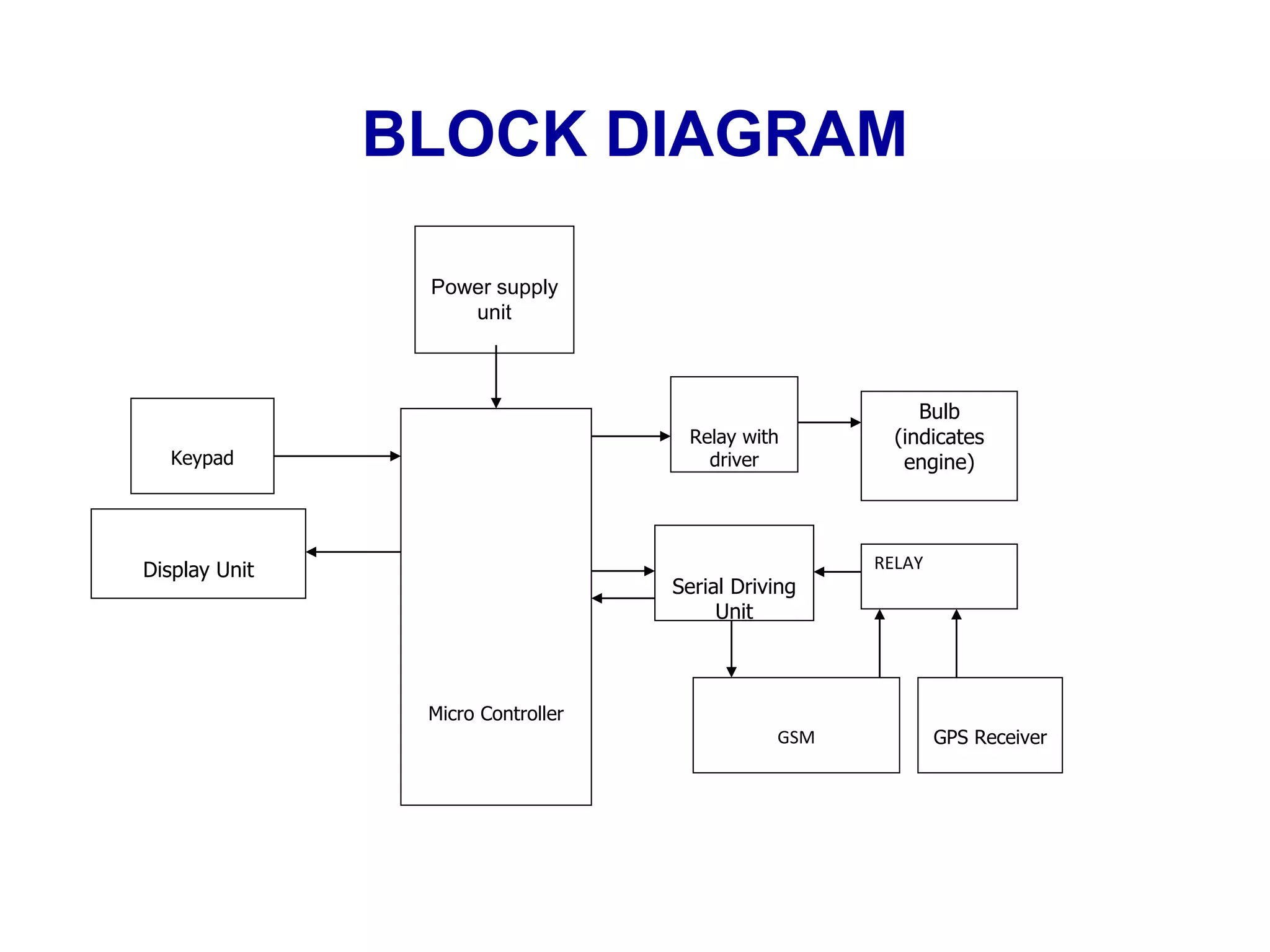
Title
ANTI VEHICLE THEFTCONTROL SYTEMUSING GPS
AND GSM
BY
DEBABRATA DUTTA
DURGESH NANDINI
SUVRANSU SEKHAR DAS
DIBYA PRAKASH
ROUTRAY
HIMANSHU SEKHAR
MISHRA
GUIDED BY
DUTTATREYA MISHRA
AIM OF THE PROJECT
To develop a prototype of a system
based on microcontroller that is used
to control the theft of a vehicle
through GSM network and also
finding its position using GPS
receiver.
PURPOSE
The main purpose of this project is protecting vehicle from
theft. Now a day’s vehicle thefts are increasing rapidly. People
have started to use the theft control systems installed in their
vehicles.
The commercially available anti-theft vehicular systems are
very expensive. And this project is developed as low cost
vehicle theft control scheme using a microcontroller and with
usage of GSM and GPS technology
BLOCK DIAGRAM
Micro Controller
Power supply
unit
Display Unit
GSM
Serial Driving
Unit
Relay with
driver
Bulb
(indicates
engine)
GPS Receiver
Keypad
RELAY
DESCRIPTION:
 A Microcontroller will be interfaced between the GSM
module and GPS receiver
 The microcontroller will keep listening to new sms arrival
. If a sms is arrived it will read the GPS location and will
send it to the user’s cell phone in the form of sms
 The GPS coordinates received from the GPS module
through sms in the form of latitudes and longitudes can be
taken and implemented in the Google maps to get the
vehicles position
 The GSM modem is a serial device that is very similar to a
GSM mobile phone in its functionality.
 The current design uses a GSM based modem for controlling
vehicle thefts by providing an option to the owner of the
vehicle to stop the vehicle immediately from the remote place
so that a vehicle is with in the nearby area limits. This can be
attained through a single SMS.
 The extra security feature provided here in the project is
provision of a secret code entry via a keypad attached to the
device to start the vehicle again only by the owner of the
vehicle as he may have the fear of taking away the vehicle by
any one else mean while, i.e. the vehicle can’t be started until
and unless the owner of the vehicle enters a correct password.
POWER SUPPLY UNIT:
 We need a 5V dc supply as operating voltage for the
microcontroller unit, GSM module and GPS module.
 The power supply unit is constructed to convert the 230V
ac supply to the required dc (5V).
• LCD DISPLAY:
 The LCD display is interfaced with the microcontroller
unit
 The data pins are connected to the I/O pins of the
microcontroller(port 2).
 The 1,16 pins are grounded and 2,15 pins are connected to
Vcc
MICROCONTROLLER:
 The microcontroller(8051) is the heart of the circuit.
 It acts as the interface between the GPS and the GSM
module
 The microcontroller is a low power CMOS 8 bit
microcontroller based on RISC architecture.
 There are 4 ports of I/O pins , the 20 pin is grounded and
40 pin is connected to Vcc , the 9 pin is the RESET pin,
 A crystal oscillator is connected to 18 and 19 pin.
 30 pin is the ALE and 29 is the PSEN pin.
GSM MODEM:
 A GSM modem is a specialized type of modem which
accepts a SIM card and operates over a subscription to a
mobile operator just like a mobile phone.
 A GSM modem can be a dedicated modem device with a
serial port.
GPS MODULE:
 The global positioning system(GPS) is a space based radio
navigation system consisting of constellation of satellites
and a network of ground stations used for monitoring and
control.
 It is a collection of satellites in space that transmit their
position in space as precise time.
 The receiver collects the data from satellites and computes
its location to get the position.
SERIAL COMMUNICATION:
 Two serial ports are required for interfacing the GPS and
GSM modules
 The modules are interfaced with the serial port of the
microcontroller.
KEYPAD & IR:
 Keypad is used for password authentication and IR
indicates the opening and closing of door
DRIVER:
 We are using an IC L293D for this purpose.
 It is a 16 pin IC from which two motors can be driven
 The 1,16 pins are connected to the ground
MAX 232
 The 15,10 pins are connected to the microcontroller and 12,
13 pins are grounded.
 The dc motor is connected to the 11,14 pins of the IC
L293D and 5V dc supply is fed to the 9 pin of the IC from
the power supply unit.
RELAY:
 A relay is a 5 pin device and its function is similar to switch.
 It is connects with the GSM and GPS module with the
microcontroller.
 The 1 pin is connected to the 5V supply and the 3 pin is
connected to the microcontroller , the 4, 5 pins are
connected to the GSM & GPS modules.
USE OF THE SYSTEM
WORKING OF THE ANTI THEFT SYSTEM
To start with first a password check is displayed on the LCD
screen. The person inputs the secret password .
 Totally three password checks are provided to enter the correct
password.
 If the passwords entered are incorrect a sms is sent to the owner
of the vehicle through the GSM module via the microcontroller.
 Here we are using one pair of IR sensors to conform if anybody
enters in the car without knowledge of the owner.
 With the help of GPS the exact location of the vehicle can be
found out ,the GPS module gathers data and send it to the
controller and the data is sent to the owner by the GSM module.
 The owner can also know the location of the vehicle at any time
by only a single sms .
FUTURE DEVELOPMENTS
 The RFID concept can applied for a enhanced security.
 A master key can be built for one way use.
 With developments in communication and electronics the
system can be upgraded.
 It can be programmed to sent a message to the police station
for immediate action.
 Can be used to monitor vehicles performance and reduce
accidents.
 Can be used for route record keeping
CONCLUSION
The anti vehicle system help in vehicular
protection .Real time knowledge of the
vehicle location and alerts can be received
with GPS position.
antivehicle theft system

antivehicle theft system

  • 1.
    Title ANTI VEHICLE THEFTCONTROLSYTEMUSING GPS AND GSM
  • 2.
    BY DEBABRATA DUTTA DURGESH NANDINI SUVRANSUSEKHAR DAS DIBYA PRAKASH ROUTRAY HIMANSHU SEKHAR MISHRA GUIDED BY DUTTATREYA MISHRA
  • 3.
    AIM OF THEPROJECT To develop a prototype of a system based on microcontroller that is used to control the theft of a vehicle through GSM network and also finding its position using GPS receiver.
  • 4.
    PURPOSE The main purposeof this project is protecting vehicle from theft. Now a day’s vehicle thefts are increasing rapidly. People have started to use the theft control systems installed in their vehicles. The commercially available anti-theft vehicular systems are very expensive. And this project is developed as low cost vehicle theft control scheme using a microcontroller and with usage of GSM and GPS technology
  • 5.
    BLOCK DIAGRAM Micro Controller Powersupply unit Display Unit GSM Serial Driving Unit Relay with driver Bulb (indicates engine) GPS Receiver Keypad RELAY
  • 6.
    DESCRIPTION:  A Microcontrollerwill be interfaced between the GSM module and GPS receiver  The microcontroller will keep listening to new sms arrival . If a sms is arrived it will read the GPS location and will send it to the user’s cell phone in the form of sms  The GPS coordinates received from the GPS module through sms in the form of latitudes and longitudes can be taken and implemented in the Google maps to get the vehicles position  The GSM modem is a serial device that is very similar to a GSM mobile phone in its functionality.
  • 7.
     The currentdesign uses a GSM based modem for controlling vehicle thefts by providing an option to the owner of the vehicle to stop the vehicle immediately from the remote place so that a vehicle is with in the nearby area limits. This can be attained through a single SMS.  The extra security feature provided here in the project is provision of a secret code entry via a keypad attached to the device to start the vehicle again only by the owner of the vehicle as he may have the fear of taking away the vehicle by any one else mean while, i.e. the vehicle can’t be started until and unless the owner of the vehicle enters a correct password.
  • 8.
    POWER SUPPLY UNIT: We need a 5V dc supply as operating voltage for the microcontroller unit, GSM module and GPS module.  The power supply unit is constructed to convert the 230V ac supply to the required dc (5V). • LCD DISPLAY:  The LCD display is interfaced with the microcontroller unit  The data pins are connected to the I/O pins of the microcontroller(port 2).  The 1,16 pins are grounded and 2,15 pins are connected to Vcc
  • 9.
    MICROCONTROLLER:  The microcontroller(8051)is the heart of the circuit.  It acts as the interface between the GPS and the GSM module  The microcontroller is a low power CMOS 8 bit microcontroller based on RISC architecture.  There are 4 ports of I/O pins , the 20 pin is grounded and 40 pin is connected to Vcc , the 9 pin is the RESET pin,  A crystal oscillator is connected to 18 and 19 pin.  30 pin is the ALE and 29 is the PSEN pin.
  • 10.
    GSM MODEM:  AGSM modem is a specialized type of modem which accepts a SIM card and operates over a subscription to a mobile operator just like a mobile phone.  A GSM modem can be a dedicated modem device with a serial port. GPS MODULE:  The global positioning system(GPS) is a space based radio navigation system consisting of constellation of satellites and a network of ground stations used for monitoring and control.  It is a collection of satellites in space that transmit their position in space as precise time.
  • 11.
     The receivercollects the data from satellites and computes its location to get the position. SERIAL COMMUNICATION:  Two serial ports are required for interfacing the GPS and GSM modules  The modules are interfaced with the serial port of the microcontroller. KEYPAD & IR:  Keypad is used for password authentication and IR indicates the opening and closing of door DRIVER:  We are using an IC L293D for this purpose.  It is a 16 pin IC from which two motors can be driven  The 1,16 pins are connected to the ground
  • 12.
  • 13.
     The 15,10pins are connected to the microcontroller and 12, 13 pins are grounded.  The dc motor is connected to the 11,14 pins of the IC L293D and 5V dc supply is fed to the 9 pin of the IC from the power supply unit. RELAY:  A relay is a 5 pin device and its function is similar to switch.  It is connects with the GSM and GPS module with the microcontroller.  The 1 pin is connected to the 5V supply and the 3 pin is connected to the microcontroller , the 4, 5 pins are connected to the GSM & GPS modules.
  • 14.
    USE OF THESYSTEM
  • 15.
    WORKING OF THEANTI THEFT SYSTEM To start with first a password check is displayed on the LCD screen. The person inputs the secret password .  Totally three password checks are provided to enter the correct password.  If the passwords entered are incorrect a sms is sent to the owner of the vehicle through the GSM module via the microcontroller.  Here we are using one pair of IR sensors to conform if anybody enters in the car without knowledge of the owner.  With the help of GPS the exact location of the vehicle can be found out ,the GPS module gathers data and send it to the controller and the data is sent to the owner by the GSM module.  The owner can also know the location of the vehicle at any time by only a single sms .
  • 16.
    FUTURE DEVELOPMENTS  TheRFID concept can applied for a enhanced security.  A master key can be built for one way use.  With developments in communication and electronics the system can be upgraded.  It can be programmed to sent a message to the police station for immediate action.  Can be used to monitor vehicles performance and reduce accidents.  Can be used for route record keeping
  • 17.
    CONCLUSION The anti vehiclesystem help in vehicular protection .Real time knowledge of the vehicle location and alerts can be received with GPS position.