1. GSM ANTI THEFT SYSTEM FOR VECHICLES
1
PORT1
8
0
5
1
8051
SMS
GSM BASED ANTI THEFT SYSTEM FOR
VECHICLES
DSF
DC Motor Control
DC Motor Control
2. TABLE OF CONTENTS
1.1 Introduction
1.2 Methodology
1.3 Scope of Work
1.4 Aims of the GSM ANTI THEFT SYSTEM FOR VECHICLES
1.5 Objectives of the GSM ANTI THEFT SYSTEM FOR VECHICLES
2.0 Theoretical Background
2.1 GSM Architecture
2.2 GSM Frequencies
2.3 Network Structure
2.4 Subscriber Identity Module (SIM)
2.5 Literature Review
2.6 GSM Security
2.7 Circuit Diagram of the GSM ANTI THEFT SYSTEM FOR VECHICLES
3.1 GSM Modem
3.1.1 Accessing GSM MODEM using Microsoft HyperTerminal
3.2 Testing of GSM Modem
3.3 List of Important AT Commands
3.4 Microcontroller – MODEM Interfacing
3.4.1. DTE and DCE
3.4.2. RS-232
2
3. 3.4.3. RTS/CTS Handshaking
3.4.4. Specifying Baud Rate, Parity & Stop bits
3.4.5 DCE Baud Rates
4.1 Initializations
4.1.1 Serial transfer using TI and RI flags
4.1.2 Validity Check
4.1.3 Display
4.2 Components List
5.1 Conclusion
5.2 Problems Encountered
5.3 Future Improvement
3
4. 1.1 Introduction:
In the present growing economy of India, the country also faces the uprising of crime Rate.
The offense has generated losses in properties, valuables and money and many Solutions are
performed to minimize and to prevent the crime. Vehicles theft, which is the main concern
for the conduct of this project, is one of the biggest crimes which are hard to eliminate.
The latest trend of Vehicles Theft involves the vehicles being towed away, and also alarm
signal capturing where the alarm disabler signal can be traced and duplicate by a thief with
the device to capture the signal and use it to disable the alarm. There are many alternatives to
prevent the vehicles theft, common vehicles alarm system which nearly all cars have the
system installed, and also Global Positioning System (GPS) where the whereabouts of the
vehicle scan be traced. Other alternatives include steering and gear lock, tire lock, hidden
“kill” switches which incapacitate fuel flow and many others.
The project and research is conducted for additional features in vehicles alarm system. The
device can be added to the present vehicles alarm system without any major modification to
it. When the vehicles alarm is triggered, through forced entry or motion sensor detection, the
in-vehicles phone will send SMS message to the owner’s mobile phone to alert him or her to
check the vehicle. Usually, vehicles owner realizes that their vehicles has been stolen long
after the incident, which the vehicles thief probably gotten away, and disables all the security
features in the car, or cannibalized the vehicles for spare parts and expensive items. This
happens when the owner is far away from the vehicle to hear the alarm. The SMS message
gives immediate alert to the vehicles owner, even if the thief gotten away with the car, so that
the owner can immediately take instant actions to notify the local police department or
contact the vehicles immobilizer service which come with most GPS car system to
immobilize the vehicle.
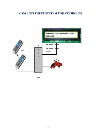
The main components of the toolkit include microcontroller, GSM modem. These
components are integrated with the device board and thus incorporate the wireless features.
The GSM modem sends the SMS. The AT commands are serially transferred to the modem.
In return the modem transmits the stored message through the wireless link. The
microcontroller used in this case is ATMEL AT89S52 .Motorola W220 is used as the GSM
modem. In this prototype model, LCD display is used for simulation purpose. The results
presented in the thesis support the proper functionalities and working of the system. The
timing diagram suggests the response of the modem to various AT (attention) commands.
4
5. 1.2 Methodology:
The method used to carry out this project is the principle of serial communication in
collaboration with embedded systems. This is a very good project for Industries. This project
has a GSM ANTI THEFT SYSTEM FOR VECHICLES, which will be used as the electronic
device, and also a GSM modem, which is the latest technology used for communication
between the mobile and the embedded devices.
System will work like when the user wants to send a sms on the mishaps like someone
try to open the door of the vehicles, gas leakage at your houses and offices; the modem sent a
message through the subscriber identity module (SIM) which is inserted in the display system
MODEM.
1.3 Scope of Work
I will use liquid crystal display for displaying the message; I will also use GSM modem
(Motorola W220) as an interface between mobile and microcontroller. It will send message to
any phone irrespective of the GSM network through the modem connected to the
programmable device.
1.4 Aims of the GSM ANTI THEFT SYSTEM FOR VECHICLES
5
6. Uses: This is very useful and innovative project. We can use this to secure our offices
and houses to save our property from mishaps.
1.5 Objectives of the ANTI THEFT SYSTEM FOR VECHICLES
Programming of the mobile phone with AT (Attention) command sequence
Interfacing the programming chip with the personal computer
Interfacing the programmable chip with the Buzzer and Sensors.
Interfacing of the mobile phone with the programmable chip
Sending messages from the remote phone to control device.
2.0 Theoretical Background
GSM (Global System for Mobile communications: originally from GROUPE Special
Mobile) is the most popular standard for mobile phones in the world. Its promoter, the GSM
Association, estimates that 80% of the global mobile market uses the standard. GSM is used
by over 3 billion people across more than 212 countries and territories . Its ubiquity makes
international roaming very common between mobile phone operators enabling subscribers to
use their phones in many parts of the world. GSM differs from its predecessors in that both
6
7. signaling and speech channels are digital, and thus is considered a second generation (2G)
mobile phone system . This has also meant that data communication was easy to build into
the system.
2.1 GSM Architecture:
GSM is a complex system and difficult to understand. The Mobile Station (MS) refers to the
mobile equipment . The Base Station Subsystem controls the radio link with the Mobile
Station. The Network Subsystem performs main functions such as switching of calls between
mobile users, mobility management operations, and proper operation and setup of a network .
These functions are controlled by the Mobile Services Switching Center (MSC).
2.4 GSM Frequencies:
GSM networks operate in a number of different frequency ranges (separated into GSM
frequency ranges for 2G and UMTS frequency bands for 3G). Most 2G GSM networks
operate in the 900 MHz or 1800 MHz bands. Some countries in the Americas (including
Canada and the United States) use the 850 MHz and 1900 MHz bands because the 900 and
1800 MHz frequency bands were already allocated. Most 3G GSM networks in Europe
operate in the 2100 MHz frequency band .
2.5 Network Structure:
The network behind the GSM seen by the customer is large and complicated in order to
provide all of the services which are required.
7
8. • The Base Station Subsystem (the base stations and their controllers).
• The Network and Switching Subsystem (the part of the network most similar to a
fixed network). This is sometimes also just called the core network.
• The GPRS Core Network (the optional part which allows packet based Internet
connections).
• All of the elements in the system combine to produce many GSM services such as
voice calls and SMS.
2.6 Subscriber Identity Module (SIM):
One of the key features of GSM is the Subscriber Identity Module, commonly known
as a SIM card. The SIM is a detachable smart card containing the user's subscription
information and phone book. This allows the user to retain his or her information after
switching handsets [10]. Alternatively, the user can also change operators while retaining the
handset simply by changing the SIM. Some operators will block this by allowing the phone to
use only a single SIM, or only a SIM issued by them; this practice is known as SIM locking,
and is illegal in some countries .
2.7 Literature Review:
This project is an implementation to the idea of the wireless communication between
a mobile phone and a microcontroller. Currently the main work that has been done on this
proposed system is through serial port to the computer but not wireless. If they want to
8
9. control the ANTI THEFT SYSTEM FOR VECHICLES design, the systems need not be
reprogrammed to control ANTI THEFT SYSTEM FOR VECHICLES changing the
programming of microcontroller. The device will send SMS to the owner mobile number, if
the security of the vehicle in danger.
2.8 GSM Security:
GSM was designed with a moderate level of security. The system was designed to
authenticate the subscriber using a pre-shared key and challenge-response. Communications
between the subscriber and the base station can be encrypted.
9
10. Fig. 2.2 Block Diagram
As we see in the above figure, there are at least three interfacing circuits, MAX-232
with Microcontroller, LCD display with microcontroller, and MAX-232 with GSM
MODEM.
2.9 Circuit Diagram of the GSM ANTI THEFT SYSTEM FOR
VECHICLES:
10
11. POWER SUPPLY:
Power supply is a reference to a source of electrical power. A device or system that
supplies electrical or other types of energy to an output load or group of loads is called a
11
12. power supply unit or PSU. The term is most commonly applied to electrical energy
supplies, less often to mechanical ones, and rarely to others.
Here in our application we need a 5v DC power supply for all electronics involved in the
project. This requires step down transformer, rectifier, voltage regulator, and filter circuit
for generation of 5v DC power. Here a brief description of all the components is given as
follows:
TRANSFORMER:
A transformer is a device that transfers electrical energy from one circuit to another through
inductively coupled conductors — the transformer's coils or "windings". Except for air-core
transformers, the conductors are commonly wound around a single iron-rich core, or around
separate but magnetically-coupled cores. A varying current in the first or "primary" winding
creates a varying magnetic field in the core (or cores) of the transformer. This varying
magnetic field induces a varying electromotive force (EMF) or "voltage" in the "secondary"
winding. This effect is called mutual induction.
If a load is connected to the secondary circuit, electric charge will flow in the secondary
winding of the transformer and transfer energy from the primary circuit to the load connected
in the secondary circuit.
The secondary induced voltage VS, of an ideal transformer, is scaled from the primary VP by a
factor equal to the ratio of the number of turns of wire in their respective windings:
By appropriate selection of the numbers of turns, a transformer thus allows an alternating
voltage to be stepped up — by making NS more than NP — or stepped down, by making it.
12
13. BASIC PARTS OF A TRANSFORMER:
In its most basic form a transformer consists of:
• A primary coil or winding.
• A secondary coil or winding.
• A core that supports the coils or windings.
Refer to the transformer circuit in figure as you read the following explanation: The primary
winding is connected to a 60-hertz ac voltage source. The magnetic field (flux) builds up
(expands) and collapses (contracts) about the primary winding. The expanding and
contracting magnetic field around the primary winding cuts the secondary winding and
induces an alternating voltage into the winding. This voltage causes alternating current to
flow through the load. The voltage may be stepped up or down depending on the design of
the primary and secondary windings.
=
REGULATOR IC (78XX):
It is a three pin IC used as a voltage regulator. It converts unregulated DC current into
regulated DC current.
13
14. Normally we get fixed output by connecting the voltage regulator at the output of the filtered
DC (see in above diagram). It can also be used in circuits to get a low DC voltage from a high
DC voltage (for example we use 7805 to get 5V from 12V). There are two types of voltage
regulators 1. fixed voltage regulators (78xx, 79xx) 2. variable voltage regulators (LM317) In
fixed voltage regulators there is another classification 1. +ve voltage regulators 2. -ve voltage
regulators POSITIVE VOLTAGE REGULATORS This include 78xx voltage regulators. The
most commonly used ones are 7805 and 7812. 7805 gives fixed 5V DC voltage if input
voltage is in (7.5V, 20V).
CIRCUIT DIAGRAM OF POWER SUPPLY:
14
15. 3.1 GSM Modem:
A GSM modem is a wireless modem that works with a GSM wireless network. A wireless
modem behaves like a dial-up modem. The main difference between them is that a dial-up
modem sends and receives data through a fixed telephone line while a wireless modem sends
and receives data through radio waves. Like a GSM mobile phone, a GSM modem requires a
SIM card from a wireless carrier in order to operate .
3.2 Testing of GSM Modem:
To use MS HyperTerminal to send AT commands to the GSM modem, the following
procedure is followed
1. I put a valid SIM (MTN) card into the GSM modem. I obtain a SIM card by subscribing to
the GSM service of a wireless network operator.
2. No need to install any driver for the GSM modem
15
16. 3. Then I set up MS HyperTerminal by selecting Start -> Programs -> Accessories ->
Communications -> HyperTerminal.
4. In the Connection Description dialog box (as shown in the screenshot given below), I enter
any file name and choose an icon I like for the connection. Then I click the OK button.
. In the Connect To dialog box, choose the COM port that your mobile phone or GSM
modem is connecting to in the Connect using combo box. I choose COM1 because my
mobile phone is connected to the COM1 port. Then click the OK button. Type "AT" in the
main window. A response "OK" will be returned from the mobile phone or GSM modem.
Type "AT+CPIN?" in the main window. The AT command "AT+CPIN?" is used to query
whether the mobile phone or GSM modem is waiting for a PIN (personal identification
number, i.e. password). If the response is "+CPIN: READY", it means the SIM card does not
require a PIN and it is ready for use. If my SIM card requires a PIN, you need to set the PIN
with the AT command "AT+CPIN=<PIN>".
[
3.3 List of Important AT Commands:
After successfully testing the MODEM for its correct operational state, I then set the
MODEM parameters like Baud rate, Echo off etc to enable easier access via a
microcontroller which I used in this project. The following are the ATCOMMAND used for
programming the gsm modem
Example: Changing and saving parameters
AT+IPR=9600[Enter] Transfer rate to 9600bps
AT&W [Enter] save parameters
AT+CMGF means convert the message to machine instruction format
AT+CPMS means selection of SMS memory
16
17. AT+CMGR means read message from a given memory location
AT+CMGD means delete message from a given memory location.
3.4 Microcontroller – Modem Interfacing:
3.4.1. DTE and DCE
The terms DTE and DCE are very common in the data communications market. DTE is short
for Data Terminal Equipment and DCE stands for Data Communications Equipment. As the
full DTE name indicates this is a piece of device that ends a communication line, whereas the
DCE provides a path for communication. Let's say I have a computer on which wants to
communicate with the Internet through a modem and a dial-up connection. To get to the
Internet I tell my modem to dial the number of my provider. After my modem has dialed the
number, the modem of the provider will answer my call and I will hear a lot of noise. Then it
becomes quiet and I see my login prompt or my dialing program tells me the connection is
established. Now I have a connection with the server from my provider and I can surf the
Internet .
3.4.2. RS-232:
In telecommunications, RS-232 is a standard for serial binary data signals connecting
between a DTE (Data terminal equipment) and a DCE (Data Circuit-terminating Equipment).
It is commonly used in computer serial ports. In RS-232, data is sent as a time-series of bits.
Both synchronous and asynchronous transmissions are supported by the standard. In addition
to the data circuits, the standard defines a number of control circuits used to manage the
connection between the DTE and DCE [14]. Each data or control circuit only operates in one
direction that is, signaling from a DTE to the attached DCE or the reverse. Since transmit
data and receive data are separate circuits, the interface can operate in a full duplex manner,
17
18. supporting concurrent data flow in both directions [15]. The standard does not define
character framing within the data stream, or character encoding.
Female 9 pin plug
3.4.3. RTS/CTS Handshaking:
The standard RS-232 use of the RTS and CTS lines is asymmetrical. The DTE asserts RTS to
indicate a desire to transmit and the DCE asserts CTS in response to grant permission. This
allows for half-duplex modems that disable their transmitters when not required, and must
transmit a synchronization preamble to the receiver when they are re enabled [16]. There is
no way for the DTE to indicate that it is unable to accept data from the DCE. A non-standard
symmetrical alternative is widely used: CTS indicates permission from the DCE for the DTE
to transmit, and RTS indicates permission from the DTE for the DCE to transmit [17]. The
"request to transmit" is implicit and continuous. The standard defines RTS/CTS as the
signaling protocol for flow control for data transmitted from DTE to DCE. The standard has
no provision for flow control in the other direction. In practice, most hardware seems to have
repurposed the RTS signal for this function [18]. A minimal “3-wire” RS-232 connection
consisting only of transmits data, receives data and ground, and is commonly used when the
full facilities of RS-232 are not required. When only flow control is required, the RTS and
CTS lines are added in a 5-wire version.
3.4.4. Specifying Baud Rate, Parity & Stop bits:
18
19. Serial communication using RS-232 requires four parameters: the baud rate of the
transmission, the number of data bits encoding a character, the sense of the optional parity
bit, and the number of stop bits. Each transmitted character is packaged in a character frame
that consists of a single start bit followed by the data bits, the optional parity bit, and the stop
bit or bits. A typical character frame encoding the letter "m" is shown here.
I specified the parameters as baud rate – 9600 bps, 8 data bits, no parity, and 1 stop bit (9600-
8 N-1). This was set in pre-operational phase while setting up the modem through the hyper
terminal, as per the serial transmission standards in 8051 microcontroller [19].
3.4.5 DCE Baud Rates:
110,300,1200,2400,4800,9600,19200,38400,57600,115200,230400,460800,921600 (Possible
Baud Rates) Baud Rate Used Power on default rate
3.5 Microcontroller – LCD Interfacing:
19
20. Above is the quite simple schematic. The LCD panel’s Enable and Register Select is
connected to the Control Port. The Control Port is an open collector / open drain output.
Therefore by incorporating the two 10K external pull up resistors, the circuit is more portable
for a wider range of computers, some of which may have no internal pull up resistors. I make
no effort to place the Data bus into reverse direction. Therefore I had wire the R/W line of the
LCD panel, into write mode. This will cause no bus conflicts on the data lines. As a result I
cannot read back the LCD’s internal Busy Flag which tells us if the LCD has accepted and
finished processing the last instruction [20]. This problem is overcome by inserting known
delays into my program. The 10k Potentiometer controls the contrast of the LCD panel.
Nothing fancy here.
I used a power supply of 5volt. The user may select whether the LCD is to operate with a 4-
bit data bus or an 8- bit data bus. If a 4-bit data bus is used, the LCD will require a total of 7
data lines. If an 8-bit data bus is used, the LCD will require a total of 11 data lines [20]. LCD
with 8-bit data bus is used for this design. The three control lines are EN, RS, and RW. EN
line must be raised/lowered before/after each instruction sent to the LCD regardless of
whether that instruction is read or write text or instruction. In short, I manipulate EN when
communicating with the LCD.
4.4 Programmer:
20
21. When we have to learn about a new computer we have to familiarize about the machine
capability we are using, and we can do it by studying the internal hardware design (devices
architecture), and also to know about the size, number and the size of the registers.
A microcontroller is a single chip that contains the processor (the CPU), non-volatile memory
for the program (ROM or flash), volatile memory for input and output (RAM), a clock and an
I/O control unit. Also called a "computer on a chip," billions of microcontroller units (MCUs)
are embedded each year in a myriad of products from toys to appliances to automobiles. For
example, a single vehicle can use 70 or more microcontrollers. The following picture
describes a general block diagram of microcontroller.
89S52: The AT89S52 is a low-power, high-performance CMOS 8-bit microcontroller with
8K bytes of in-system programmable Flash memory. The device is manufactured using
Atmel’s high-density nonvolatile memory technology and is compatible with the industry-
standard 80C51 instruction set and pin out. The on-chip Flash allows the program memory to
be reprogrammed in-system or by a conventional nonvolatile memory pro-grammar. By
combining a versatile 8-bit CPU with in-system programmable Flash on a monolithic chip,
the Atmel AT89S52 is a powerful microcontroller, which provides a highly flexible and cost-
effective solution to many, embedded control applications. The AT89S52 provides the
following standard features: 8K bytes of Flash, 256 bytes of RAM, 32 I/O lines, Watchdog
timer, two data pointers, three 16-bit timer/counters, a six-vector two-level interrupt
architecture, a full duplex serial port, on-chip oscillator, and clock circuitry. In addition, the
AT89S52 is designed with static logic for operation down to zero frequency and supports two
software selectable power saving modes. The Idle Mode stops the CPU while allowing the
RAM, timer/counters, serial port, and interrupt system to continue functioning. The Power-
down mode saves the RAM con-tents but freezes the oscillator, disabling all other chip
functions until the next interrupt
21
22. The hardware is driven by a set of program instructions, or software. Once familiar with
hardware and software, the user can then apply the microcontroller to the problems easily.
The pin diagram of the 8051 shows all of the input/output pins unique to microcontrollers:
22
23. The following are some of the capabilities of 8051 microcontroller.
Internal ROM and RAM
I/O ports with programmable pins
Timers and counters
Serial data communication
The 8051 architecture consists of these specific features:
16 bit PC &data pointer (DPTR)
8 bit program status word (PSW)
8 bit stack pointer (SP)
Internal ROM 4k
Internal RAM of 128 bytes.
4 register banks, each containing 8 registers
80 bits of general purpose data memory
32 input/output pins arranged as four 8 bit ports: P0-P3
23
24. Two 16 bit timer/counters: T0-T1
Two external and three internal interrupt sources Oscillator and
clock circuits.
4.7 Component List:
ANTI THEFT SYSTEM FOR VECHICLES
Name Capacity Quantity Code
Regulator 7805 1 U1
Capacitor 1000µf 1 C1
Capacitor 10µf 1 C2
Ceramic Capacitor 22pf 2 C3,C4
Diode 4 D1,D2,D3,D4
Push Button 1
Mobile Phone 1
LCD 16*2 1
40 Pin Base 1 U2
8 Pin Base 1 U4
IR Receiver 1 D6
8051(AT89S52) 1
LM358 1
Oscillator 11.0592mhz 1 X1
LED 1 D5
Resistance 220Ω 2 R1,R4
Resistance 1k 1 R3
24
25. Resistance 10k 3 R2,R5,R6
Buzzer 1 BUZ1
BC547 1 Q1
Port 100k 3 RV1,RV2,RV3
MQ6 1 M
Resistance 1m Ω 1 R7
Read Switch 1
5.1 Conclusion:
In the present growing economy of India, the country also faces the uprising of crime
Rate. The offense has generated losses in properties, valuables and money and many
Solutions are performed to minimize and to prevent the crime. Vehicles theft, which is the
main concern for the conduct of this project, is one of the biggest crimes which are hard
to eliminate.
The latest trend of Vehicles theft involves the vehicles being towed away, and also alarm
signal capturing where the alarm disabler signal can be traced and duplicate by a thief with
the device to capture the signal and use it to disable the alarm. There are many alternatives to
prevent the vehicles theft, common vehicles alarm system which nearly all cars have the
system installed, and also Global Positioning System (GPS) where the whereabouts of the
vehicle scan be traced. Other alternatives include steering and gear lock, tire lock, hidden
“kill” switches which incapacitate fuel flow and many others.
The main aim of the project will be to design a SMS electronic ANTI THEFT SYSTEM FOR
VECHICLES toolkit which can replace the traditional ANTI THEFT SYSTEM FOR
VECHICLES. The toolkit send SMS to house owner number, the system is made efficient
by SIMs so that the SMS can be received by number of devices boards in a locality using
techniques of time division multiple access.
5.2 Problem Encountered
During soldering, many of the connection become short cktd. So we desolder the
connection and did soldering again.
A leg of the crystal oscillator was broken during mounting. So it has to be replaced.
LED`s get damaged when we switched ON the supply so we replace it by the new one.
25
26. TROUBLESHOOT
Care should be taken while soldering. There should be no shorting of joints.
Proper power supply should maintain.
5.2 Future Improvement:
• In my project I am sending messages through GSM network and Control the home
devices by utilizing AT (ATTENTION) commands. The same principle can be applied
to display the message on electronics display board appliances at a distant location.
• Robots can be controlled in a similar fashion by sending the commands to the robots.
These commands are read by using AT commands and appropriate action is taken. This
can be used for spy robots at distant locations, utilized by the military to monitor
movement of enemy troops.
• Currently farmers have to manually put on or off pumps, drippers etc by using electric
switches. Using the principle of AT commands we can put on or off these appliances
remotely.
REFERENCES
1. The 8051Microcontroller by Kenneth J. Ayala
2. The 8051 Microcontroller and Embedded Systems by Muhammad Ali Mazidi.
3. Principles and Applications of GSM by Vijay Garg.
4. http://www.mobilegpsonline.com/downloads/GM28-29%20Datasheet%20R1G.pdf
5. http://www.mobilegpsonline.com/GSMJC01Spec.pdf
6. http://www.visualgsm.com/wire_sms_index.htm
7. http://en.wikipedia.org/wiki/Gsm
26
27. TROUBLESHOOTING MANUAL FOR THE GSM ANTI THEFT
SYSTEM FOR VECHICLES:
1. SYSTEM NOT POWER : check If the GREEN led IS POWER on and also check if
the output voltage from the power supply is 5V or approximately
2. SYSTEM POWER BUT NO DISPLAY ON THE LCD: press the reset button on
the system. The reset button is indicated with red color
3. NO MESSAGES ON THE LCD: check if the headphone is connected to the phone
and also check if the phone is power
4. SYSTEM HANGED: press the rest button to re-initialize the memory of the
embedded system
5. SYSTEM SHOWS SPECIAL CHARACTER: changed the max232 driver inside
the system. Max232 is a receiver transmitter driver that is having 16pins
6. LCD CONTRAST IS FADED: rotate the potentiometer in the front panel of the
LCD to see the text clearly.
27
28. 7. BLANK OUTPUT DISPLAY: open the entire system and locate crystal oscillator.
Crystal oscillator is harsh in colour. Replace the crystal oscillator with exactly
11.0592 MHz.
8. FAILS TO CONTROL DEVICE: Ensure that there is no messages on the phone
memory and then reset the LCD also make sure the character send does not exceed 16
characters. Also make sure you put security code before the messages and you are
sending the messages to the appropriate number. The format of the messages is
“12345 fanon.
9. NO WELCOME MESSAGE AS YOU POWER ON: The system should display a
scrolling welcome message as you power on the system. The welcome message to be
display is “WELCOME TO PROJECTS”. If no welcome message, ensure to connect
the headphone to the mobile phone or you can use your hand to touch the headphone
10. NO RESPONSE FROM THE HEADPHONE: You can change the headphone and
locate the RX, TX, and GND from the headphone before connecting it to the entire
system.
11. IF THE MODEM WAS STOLEN: Get another phone from a GSM shop and
replace it, ensure you program the phone and make sure the communication rate is set
to 9600bps.
28