The document presents an accident detection system utilizing Arduino Uno, which employs an accelerometer to detect accidents and alerts emergency services via GSM and GPS modules. The system enables rapid communication of location data to responders, thereby addressing delays in rescue efforts that contribute to road accident fatalities. This effective solution aims to enhance safety on roads and reduce the loss of lives from accidents in densely populated areas.
![International Journal of Trend in Scientific Research and Development (IJTSRD) @ www.ijtsrd.com eISSN: 2456-6470
@ IJTSRD | Unique Paper ID – IJTSRD27840 | Volume – 3 | Issue – 5 | July - August 2019 Page 2093
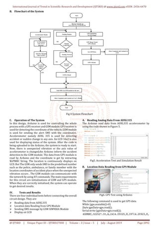
The location can be get from above $GPRMC String. This
String means
$ represents "NMEA Data"
GP represents "GPS position"
RMC represents "Recommended Minimum sentence C"
022527.00 represents "HHMMSS.SS" (Hours, Minutes,
Second)
A represents "Status // A=active"
2414.85025 represents "DDMM.MMMMM" ( latitude
Degree, Minutes)
N represents "Direction N=North, S= South"
09714.28923 represents " DDDMM.MMMMM" (
Longitude Degree, Minutes)
E represents "Direction E= East, W=West".
C. Sending SMS message by GSM SIM900A Module
By using the AT commands describedinTable2GSMmodule
is tested.
Table2. AT Commands
Commands Description
ATA Answer Command
ATD Dial Command
AT+CMGS Send SMS message
AT+CMGF Select SMS Message format
AT+CNMI New SMS Message indication
AT+CPIN Check Pin
Figure 7. GSM Test
D. Displaying on LCD
Interfacing between LCD and Arduino is also tested.The16x
2 LCD display is command by four bit mode.
Figure8. View of LCD Test
V. Final Installation and Tests
Since the individual tests are satisfied, then all devices are
carefully connected and upload the complete code on
Arduino. The maximum limit acceleration is predefined for
accident detection. Whenaccidentis detected,the messageis
sent as shown in Figure.
VI. Conclusion and Discussion
Nowadays, to provide a suitable safety of road accident
preventing and detection system is becoming one of the
most important things for the future generation. There is an
increasing the death of peoplebecauseofroadaccidents. The
demand for this process is to save life just on time after the
accident has occurred. There are so many ways to know the
location after the accident has occurred. This GPS and GSM
based automatic accident detection system is also one of the
less delay time and the most effectivesystemforthis present
days.
REFERENCES
[1] Araya D.S and Athulya C.K Accident Alert and Tracking
Using Arduino, Dept. of Electrical and Electronics
Engineering, Mar Baselios Institute of Technology and
Science, Nellimattom, Kerala, India, (2018).
[2] Waleed Mohy Eldeen Ibrahem: Accident Detectionand
Reporting, System using GPS and GSM Module,
Almughtaribeen University College of Engineering,
Department of Communication Fifth Year Bachelors,
(2017).
[3] Jonathan Vail: Global Positioning System, U.S
Enviromental Protection Angency Science and
Ecosystem Support Division Athens, Georgia, (2015).
[4] Kommineni Rakesh: Vehicle Tracking and Accident
Alert System, National Institute of Technology
Rourkela, (2014).
[5] Automatic Traffic Accident Detection and AlertSystem
International Journal Technology Exploration an d
Learning (IJTEL), Volume 1, Issue 1, (August 2012).](https://image.slidesharecdn.com/400accidentdetectionsystemusingarduinouno-190917124504/85/Accident-Detection-System-using-Arduino-Uno-4-320.jpg)


