Downloaded 448 times


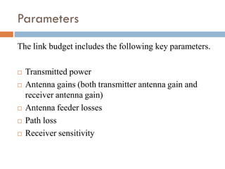
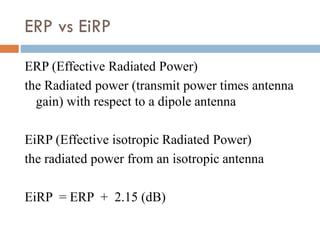


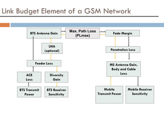
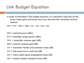
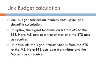
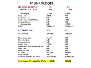


This document provides an overview of GSM link budget calculations. It defines key terms used in link budgets such as effective radiated power, antenna gain, diversity gain, receiver sensitivity, path loss, and fade margin. It explains the objectives of calculating a link budget are to estimate maximum allowable path loss, compute required effective isotropically radiated power for a balanced link, estimate coverage design thresholds, and evaluate technology performance. It also provides examples of uplink and downlink link budget calculations for a GSM network and defines indoor, in-car, and outdoor coverage requirements.


