Downloaded 111 times

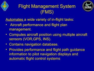
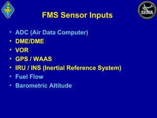
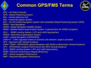

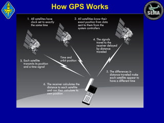
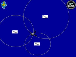

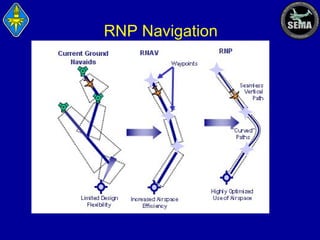
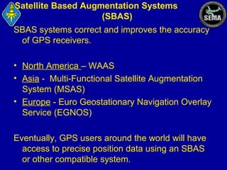
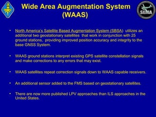
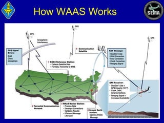
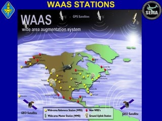
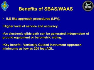
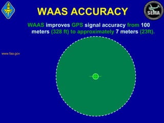
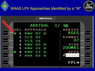
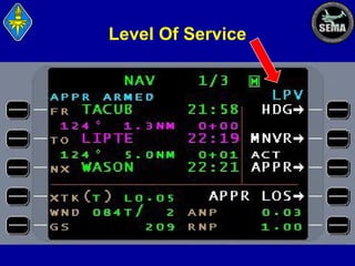
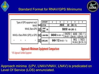
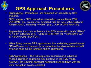

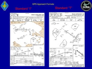
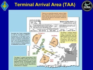
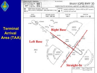
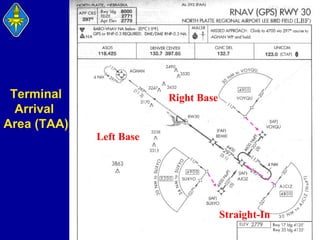
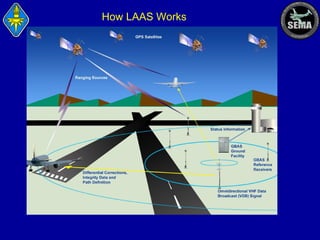
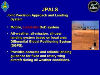
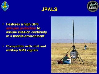
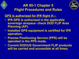

This document provides an overview of global positioning systems and flight management systems used in aircraft. It defines key terms and describes the components and functions of GPS, WAAS, INS, barometric altimeters, and how they integrate with an aircraft's flight management system. It explains how GPS and WAAS provide lateral and vertical navigation guidance for different types of instrument approaches, including LNAV, LNAV+V, LNAV/VNAV, LP, and LPV approaches. It also covers requirements, limitations, and safety aspects of using GPS and WAAS for navigation.