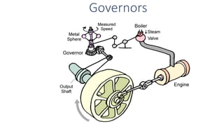
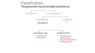
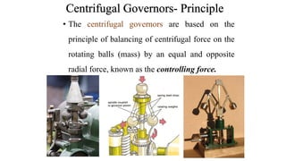
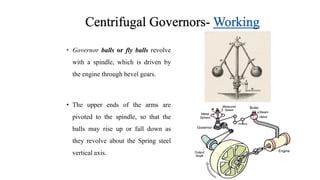
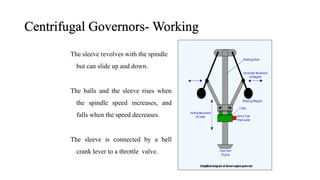
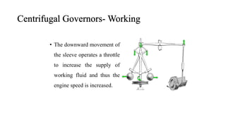
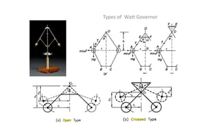
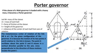
A governor is a device that regulates the speed of an engine by controlling the fuel supply. There are two main types - centrifugal and inertia governors. Centrifugal governors use rotating masses (flyballs) where the centrifugal force is balanced by a controlling force like tension in the arms. As speed increases, the flyballs rise and the controlling mechanism reduces the fuel supply. Common centrifugal governors include the Watt, Porter, Proell, and Hartnell governors which differ in their specific configurations and controlling mechanisms like dead weights or springs. The governor acts to maintain a constant average speed as the engine load varies.


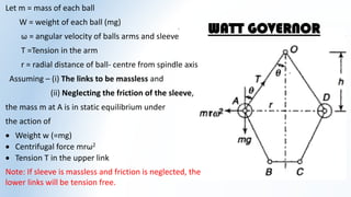


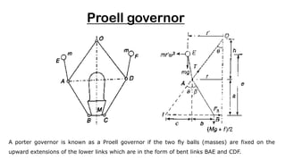
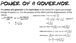
![Considering the equilibrium of the link BAE which is under the action of :-
Weight of the ball, mg
Centrifugal force, mr’ω2
Tension in the link AO, T
Weight of sleeve and friction,
𝟏
𝟐
(𝐌𝐠 ± 𝐟)
Taking moment about I the instantaneous centre of link BAE
𝐦𝐫′
𝛚𝟐
𝐞 = 𝐦𝐠 (𝐜 + 𝐫 − 𝐫′
) +
𝐌𝐠 ± 𝐟
𝟐
(𝐜 + 𝐛)
Where b, c, a and r are the dimensions as indicated in the diagram.
𝐦𝐫′𝛚𝟐 =
𝟏
𝐞
[𝐦𝐠 𝐜 + 𝐫 − 𝐫′ +
𝐌𝐠±𝐟
𝟐
𝐜 + 𝐛 ] (dividing equation by e)
Considering the situation where AE is vertical, i.e. neglecting its obliquity,
𝐦𝐫𝛚𝟐
=
𝟏
𝐞
[𝐦𝐠𝐜 +
𝐌𝐠 ± 𝐟
𝟐
𝐜 + 𝐛 ]
=
𝐚
𝐞
[𝐦𝐠
𝐜
𝐚
+
𝐌𝐠 ± 𝐟
𝟐
𝐜
𝐚
+
𝐛
𝐚
] (multipling and dividing equation by a)](https://image.slidesharecdn.com/governorsppt-240314055832-b332e67f/85/Governors-ppt-pdf-24-320.jpg)
![=
𝒂
𝒆
[𝒎𝒈
𝒄
𝒂
+
𝑴𝒈 ± 𝒇
𝟐
𝒄
𝒂
+
𝒃
𝒂
]
=
𝒂
𝒆
[𝒎𝒈 𝒕𝒂𝒏 𝜽 +
𝑴𝒈 ± 𝒇
𝟐
𝒕𝒂𝒏 𝜽 + 𝒕𝒂𝒏 𝜷 ]
Taking ‘tanθ’ common and
𝒕𝒂𝒏 𝜷
𝒕𝒂𝒏 𝜽
= 𝒌
=
𝒂
𝒆
𝒕𝒂𝒏 𝜽 [𝒎𝒈 +
𝑴𝒈 ± 𝒇
𝟐
𝟏 + 𝒌 ]
𝒎𝒓𝝎𝟐
=
𝒂
𝒆
𝒓
𝒉
[𝒎𝒈 +
𝑴𝒈 ± 𝒇
𝟐
𝟏 + 𝒌 ]
Dividing and multiplying by ‘g’
𝟐𝝅𝑵
𝟔𝟎
𝟐
=
𝒂
𝒆
𝒈
𝒉
𝟐𝒎𝒈 + 𝑴𝒈 ± 𝒇 𝟏 + 𝒌
𝟐𝒎𝒈
(Taking g= 9.81 m/s2)
𝑵𝟐
=
𝟖𝟗𝟓
𝒉
𝒂
𝒆
𝟐𝒎𝒈 + 𝑴𝒈 ± 𝒇 𝟏 + 𝒌
𝟐𝒎𝒈](https://image.slidesharecdn.com/governorsppt-240314055832-b332e67f/85/Governors-ppt-pdf-25-320.jpg)


![Mechanics of machines ii [159533]](https://cdn.slidesharecdn.com/ss_thumbnails/eqcuqcsctmmlwdqr1k8i-signature-561ae61528e89c87b5e046ae92c4f43fe3c9e05593c8aae419f52d477405ade4-poli-160512171914-thumbnail.jpg?width=640&height=640&fit=bounds)


