Downloaded 897 times
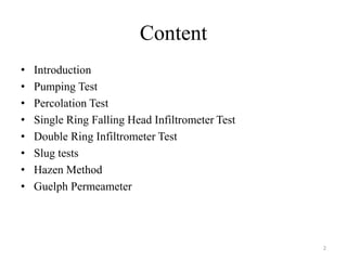
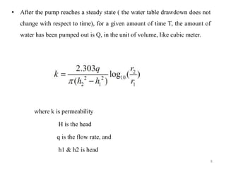
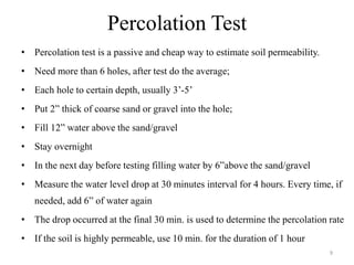
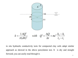

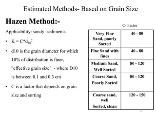
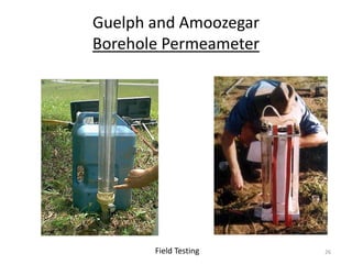
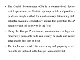


The document describes various methods for measuring soil permeability in the field, including pumping tests, percolation tests, single ring falling head infiltrometer tests, double ring infiltrometer tests, slug tests, and estimated methods based on grain size like the Hazen and Guelph permeameter methods. It provides details on the principles, procedures, analysis, and limitations of each method. Pumping tests and percolation tests are described as active and passive ways respectively to determine the permeability coefficient. Equations for analyzing slug test data and determining permeability from infiltrometer tests are also presented.


![Geotechnical Engineering-I [Lec #27: Flow Nets]](https://cdn.slidesharecdn.com/ss_thumbnails/27-180924141458-thumbnail.jpg?width=640&height=640&fit=bounds)


![Geotechnical Engineering-II [Lec #2: Mohr-Coulomb Failure Criteria]](https://cdn.slidesharecdn.com/ss_thumbnails/2-180930132603-thumbnail.jpg?width=640&height=640&fit=bounds)


