2
Soil Mechanics-II
Objectives:
To apply principles of soil mechanics to engineering
problems pertaining to retaining structures, foundations
and embankments.
Retaining Structures include Retaining wall, dikes, dams
etc.
Foundation: Types and design principles
Embankments: Filling and cutting etc.
3.
Course Overview
1. Permeability
Permeability through stratified layer of soils.
Seepage,
Quick sand conditions,
Design of filters.
3
4.
2. Stress Distribution
Westergard and Boussineq's theories.
Pressure bulb,
stress distribution diagram on horizontal and
vertical planes.
Stress at a point outside the loaded area.
Newmark's influence charts.
Vertical stresses due to a line and strip loads.
Fadum's charts, approximate method.
4
5.
3. Consolidation
Normallyconsolidated and over-consolidated
clays.
Detennination of pre-consolidation pressure.
Time-settlement diagrams.
Settlement analysis.
Theories of settlement of building.
5
6.
4. Earth Pressures
Active and passive earth pressure.
Pressure at rest.
Coulomb's and Rankine's theories.
Pencelete method.
Coulmann's method.
6
7.
5. Bearing Capacity
Definition: gross, net, ultimate, safe and
allowable bearing capacity.
Sources of obtaining bearing capacity.
Presumptive values from Codes.
Plate loading and penetration tests.
Terzaghi's theory and analysis.
Hanson's theory,
Effect of water table on bearing capacity
7
8.
6. Stability ofSlopes
Types of slopes,
Factors affecting stability,
Methods of analysis: Taylor's stability number
method, Swedish circle method.
Types of failure and remedial measurements.
8
9.
7. SoilStabilization
Basic principles and objectives.
Various methods of soil stabilization.
9
10.
8. Earthen Dams
Types of dams. Components and functions,
Earth dams.
General design consideration and
Typical cross-section.
General Design Considerations.
10
11.
9. Introduction todeep foundations:
Types of piles,
Load carrying capacity of piles,
Group action, negative skin friction,
Pile load test.
11
12.
10. Soil Improvement:
Basic principles ,objectives and methods.
11. Soil Dynamics:
sources of dynamic loading,
spring-mass-dashpot system,
application to machine foundations,
liquefaction.
12
13.
13
Distribution of Marks:
Total Marks: 100
Sessional Marks: 60
Assignments: 10
Quiz: 10
Mid Semester Exam: 20
Practical/Viva voce Exam: 20
Final End Semester Exam: 40
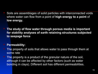
Soils areassemblages of solid particles with interconnected voids
where water can flow from a point of high energy to a point of
low energy.
The study of flow water through porous media is important
for stability analyses of earth retaining structures subjected
to seepage force
Permeability:
The property of soils that allows water to pass through them at
some rate
The property is a product of the granular nature of the soil,
although it can be affected by other factors (such as water
bonding in clays). Different soil has different permeabilities.
15
16.
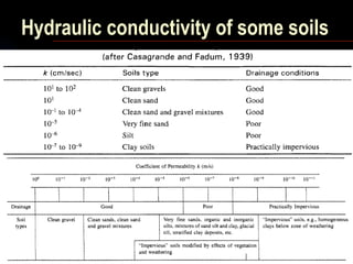
The permeabilityof soils has a decisive effect on
the stability of foundations, seepage loss through
embankments of reservoirs, drainage of sub
grades, excavation of open cuts in water bearing
sand, rate of flow of water into wells and many
others.
16
17.
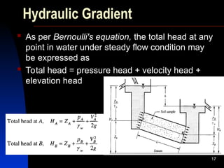
Hydraulic Gradient
Asper Bernoulli's equation, the total head at any
point in water under steady flow condition may
be expressed as
Total head = pressure head + velocity head +
elevation head
17
18.
18
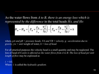
As the waterflows from A to B, there is an energy loss which is
represented by the difference in the total heads HA, and HD
where, pA and pB = pressure heads, VA and VB = velocity, g - acceleration due to
gravity, yw = unit weight of water, h = loss of head.
For all practical purposes the velocity head is a small quantity and may be neglected. The
loss of head of h units is effected as the water flows from A to B. The loss of head per unit
length of flow may be expressed as
i = h/L
Where i is called the hydraulic gradient.
19.
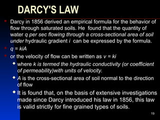
DARCY'S LAW
Darcyin 1856 derived an empirical formula for the behavior of
flow through saturated soils. He found that the quantity of
water q per sec flowing through a cross-sectional area of soil
under hydraulic gradient i can be expressed by the formula.
q = kiA
or the velocity of flow can be written as v = ki
where k is termed the hydraulic conductivity (or coefficient
of permeability)with units of velocity.
A is the cross-sectional area of soil normal to the direction
of flow
It is found that, on the basis of extensive investigations
made since Darcy introduced his law in 1856, this law
is valid strictly for fine grained types of soils.
19
20.
METHODS OF DETERMINATIONOF HYDRAULIC
CONDUCTIVITY OF SOILS
Methods that are in common use for determining the
coefficient of permeability k can be classified under
laboratory and field methods.
Laboratory methods:
Constant head permeability method
Falling head permeability method
Field methods:
Pumping tests
Bore hole tests
Indirect Method:
Empirical correlations
20
21.
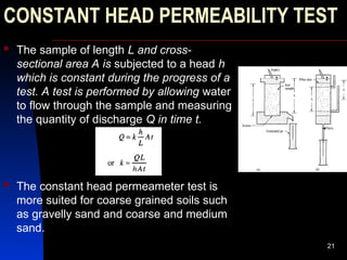
CONSTANT HEAD PERMEABILITYTEST
The sample of length L and cross-
sectional area A is subjected to a head h
which is constant during the progress of a
test. A test is performed by allowing water
to flow through the sample and measuring
the quantity of discharge Q in time t.
The constant head permeameter test is
more suited for coarse grained soils such
as gravelly sand and coarse and medium
sand.
21
22.
Problem
A constanthead permeability test was carried
out on a cylindrical sample of sand 4 in. in
diameter and 6 in. in height. 10 in3 of water was
collected in 1.75 min, under a head of 12 in.
Compute the hydraulic conductivity in ft/year and
the velocity of flow in ft/sec.
22
23.
HYDRAULIC CONDUCTIVITY INSTRATIFIED
LAYERS OF SOILS
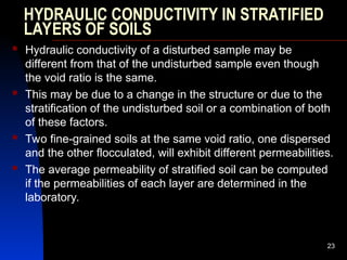
Hydraulic conductivity of a disturbed sample may be
different from that of the undisturbed sample even though
the void ratio is the same.
This may be due to a change in the structure or due to the
stratification of the undisturbed soil or a combination of both
of these factors.
Two fine-grained soils at the same void ratio, one dispersed
and the other flocculated, will exhibit different permeabilities.
The average permeability of stratified soil can be computed
if the permeabilities of each layer are determined in the
laboratory.
23
24.
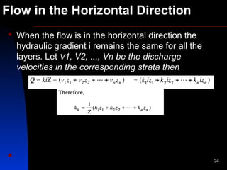
Flow in theHorizontal Direction
When the flow is in the horizontal direction the
hydraulic gradient i remains the same for all the
layers. Let V1, V2, ..., Vn be the discharge
velocities in the corresponding strata then
24
Flow in theVertical Direction
26
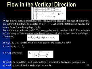
When flow is in the vertical direction, the hydraulic gradients for each of the layers
are different. Let these be denoted by i1, i2……. in. Let h be the total loss of head as the
water flows from the top layer to the
bottom through a distance of Z. The average hydraulic gradient is h/Z. The principle
of continuity of flow requires that the downward velocity be the same in each layer.
Therefore,
If h1,h2,h3…..hn are the head losses in each of the layers, we have
h = h1+h2+h3+…..+hn
Solving the above:
It should be noted that in all stratified layers of soils the horizontal permeability is
generally greater than the vertical permeability
27.
EMPIRICAL CORRELATIONS FORHYDRAULIC
CONDUCTIVITY
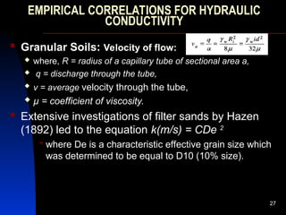
Granular Soils: Velocity of flow:
where, R = radius of a capillary tube of sectional area a,
q = discharge through the tube,
v = average velocity through the tube,
µ = coefficient of viscosity.
Extensive investigations of filter sands by Hazen
(1892) led to the equation k(m/s) = CDe 2
where De is a characteristic effective grain size which
was determined to be equal to D10 (10% size).
27
28.
The essential pointsare:
1. The flow of water through soils is governed by Darcy's
law, which states that the average flow velocity is
proportional to the hydraulic gradient.
2. The proportionality coefficient in Darcy's law is called
the coefficient of permeability or hydraulic conductivity,
k.
3. The value of k is influenced by the void ratio, particle
size distribution, and the wholeness of the soil mass.
4. Homogeneous clays are practically impervious while
sands and gravels are pervious.
28
29.
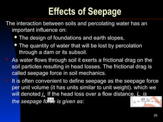
Effects of Seepage
Theinteraction between soils and percolating water has an
important influence on:
The design of foundations and earth slopes,
The quantity of water that will be lost by percolation
through a dam or its subsoil.
As water flows through soil it exerts a frictional drag on the
soil particles resulting in head losses. The frictional drag is
called seepage force in soil mechanics.
It is often convenient to define seepage as the seepage force
per unit volume (it has units similar to unit weight). which we
will denoted js. If the head loss over a flow distance, L. is
the seepage force is given as:
29
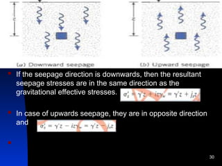
30.
If theseepage direction is downwards, then the resultant
seepage stresses are in the same direction as the
gravitational effective stresses.
In case of upwards seepage, they are in opposite direction
and
30
31.
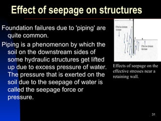
Effect of seepageon structures
Foundation failures due to 'piping' are
quite common.
Piping is a phenomenon by which the
soil on the downstream sides of
some hydraulic structures get lifted
up due to excess pressure of water.
The pressure that is exerted on the
soil due to the seepage of water is
called the seepage force or
pressure.
31
Effects of seepage on the
effective stresses near a
retaining wall.
32.
Effects of SeepageCont’d
In the stability of slopes, the seepage force is a very
important factor. Shear strengths of soils are
reduced due to the development of neutral stress or
pore pressures.
A detailed understanding of the hydraulic conditions is
therefore essential for a satisfactory design of
structures. The computation of seepage loss under
or through a dam, the uplift pressures caused by the
water on the base of a concrete dam and the effect
of seepage on the stability of earth slopes can be
studied by constructing flow nets.
32
33.
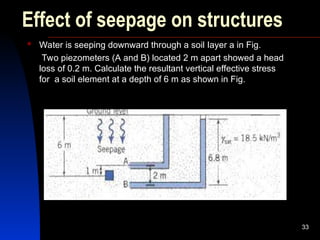
Effect of seepageon structures
Water is seeping downward through a soil Iayer a in Fig.
Two piezometers (A and B) located 2 m apart showed a head
loss of 0.2 m. Calculate the resultant vertical effective stress
for a soil element at a depth of 6 m as shown in Fig.
33
34.
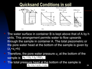
Quicksand Conditions insoil
The water surface in container B is kept above that of A by h
units. This arrangement permits water to flow upwards
through the sample in container A. The total piezometric or
the pore water head at the bottom of the sample is given by
(z1+z2+h)
Therefore, the pore water pressure uc at the bottom of the
sample is
The total pressure head at the bottom of the sample is
34
35.
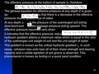
The effectivepressure at the bottom of sample is, therefore
The general equation for effective pressure at any depth Z is given
as: indicates that there is a decrease in the effective
pressure due to upward flow of water.
At any depth z, is the pressure of the submerged soil acting
downward and is the seepage pressure acting upward. The
effective pressure becomes zero when
It indicates that the effective pressure reduces to zero when the
hydraulic gradient attains a maximum value which is equal to the ratio
of the submerged unit weight of soil and the unit weight of water.
This gradient is known as the critical hydraulic gradient ic. In such
cases, cohesion less soils lose all of their shear strength and bearing
capacity and a visible agitation of soil grains is observed. This
phenomenon is known as boiling or a quick sand condition
35
36.
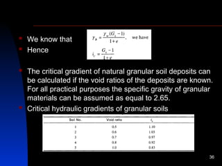
We knowthat
Hence
The critical gradient of natural granular soil deposits can
be calculated if the void ratios of the deposits are known.
For all practical purposes the specific gravity of granular
materials can be assumed as equal to 2.65.
Critical hydraulic gradients of granular soils
36
37.
Quick conditionsare common in excavations below the
ground water table. This can be prevented by lowering the
ground water elevation by pumping before excavation.
Quick conditions occur most often in fine sands or silts and
cannot occur in coarse soils.
The larger the particle size, the greater is the porosity. To
maintain a critical gradient of unity, the velocity at which
water must be supplied at the point of inflow varies as the
permeability.
Therefore a quick condition cannot occur in a coarse soil
unless a large quantity of water can be supplied.
37
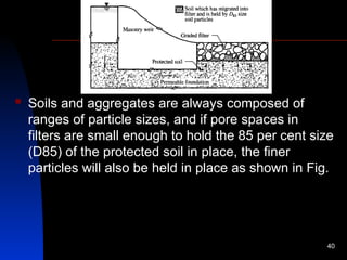
38.
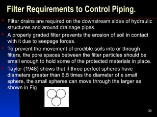
Filter Requirements toControl Piping.
Filter drains are required on the downstream sides of hydraulic
structures and around drainage pipes.
A properly graded filter prevents the erosion of soil in contact
with it due to seepage forces.
To prevent the movement of erodible soils into or through
filters, the pore spaces between the filter particles should be
small enough to hold some of the protected materials in place.
Taylor (1948) shows that if three perfect spheres have
diameters greater than 6.5 times the diameter of a small
sphere, the small spheres can move through the larger as
shown in Fig
39
39.
Soils andaggregates are always composed of
ranges of particle sizes, and if pore spaces in
filters are small enough to hold the 85 per cent size
(D85) of the protected soil in place, the finer
particles will also be held in place as shown in Fig.
40
40.
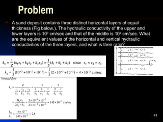
Problem
A sanddeposit contains three distinct horizontal layers of equal
thickness (Fig below.). The hydraulic conductivity of the upper and
lower layers is 103
cm/sec and that of the middle is 102
cm/sec. What
are the equivalent values of the horizontal and vertical hydraulic
conductivities of the three layers, and what is their ratio?
41


![Geotechnical Engineering-I [Lec #23: Soil Permeability]](https://cdn.slidesharecdn.com/ss_thumbnails/23-180924141141-thumbnail.jpg?width=640&height=640&fit=bounds)


