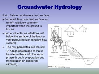
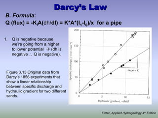
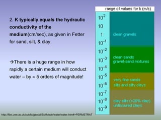
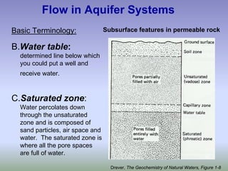
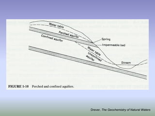
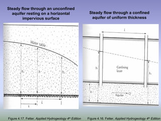
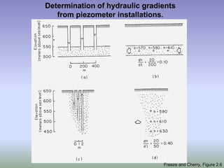
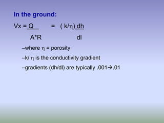
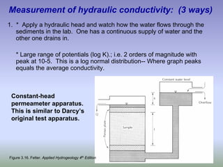
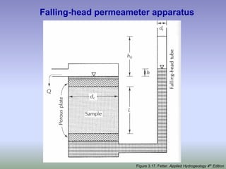
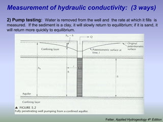
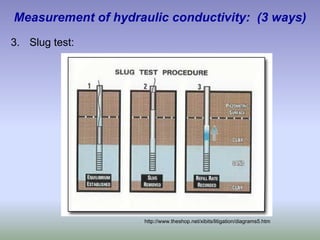
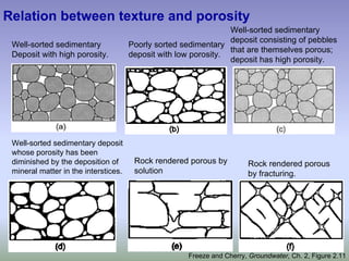
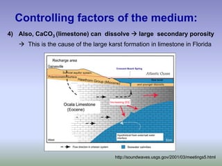
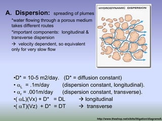
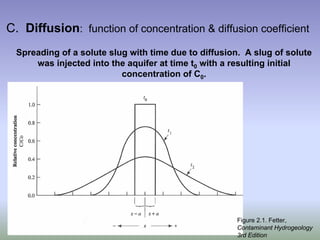
This document discusses key concepts in groundwater hydrology. It begins by outlining the different pathways water can take when it rains, including runoff, interflow, and percolation. It then explains how rainfall can raise water tables and increase stream flow. Darcy's law is introduced, which states that groundwater flow is proportional to the hydraulic gradient and conductivity of the medium. Important groundwater terminology is defined, including the saturated and unsaturated zones, water table, and capillary fringe. Factors that control groundwater flow rates, such as porosity, grain size, and packing, are examined. Measurement techniques for determining hydraulic conductivity, including permeameter tests and slug tests, are also covered.
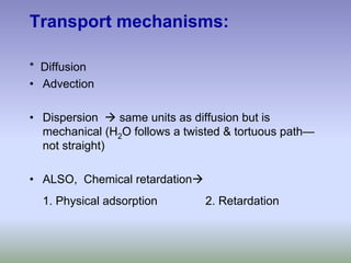
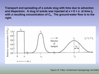
![Vx = VH2O/ [1 + KD ( ρ/η)] Solubility of organics in H2O
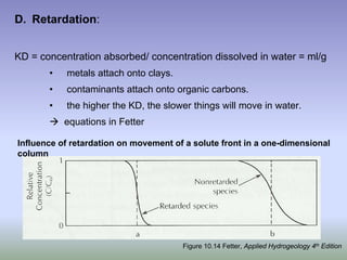
•KD is proportional to Koc ( octonal and water).
•KD is proportional to the organic carbon content -- the higher the KD, the more
things attach onto organic carbon, and it moves slower.
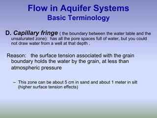
Vertical migration, in
feet per 100 y, of
various synthetic
organic compounds
through a soil with
hydraulic
conductivity of 1.6 x
10–8 cm/s, hydraulic
gradient of 0.222,
bulk density of 2.00
g/cm3, particle
density of 2.65,
effective porosity of
0.22, and soil
organic carbon
content of 0.5%.
Figure 10.16. Fetter, Applied Hydrogeology 4th Edition](https://image.slidesharecdn.com/groundwaterhydrology-230605055919-fe125fc9/85/Groundwater-Hydrology-pdf-52-320.jpg)