Downloaded 323 times
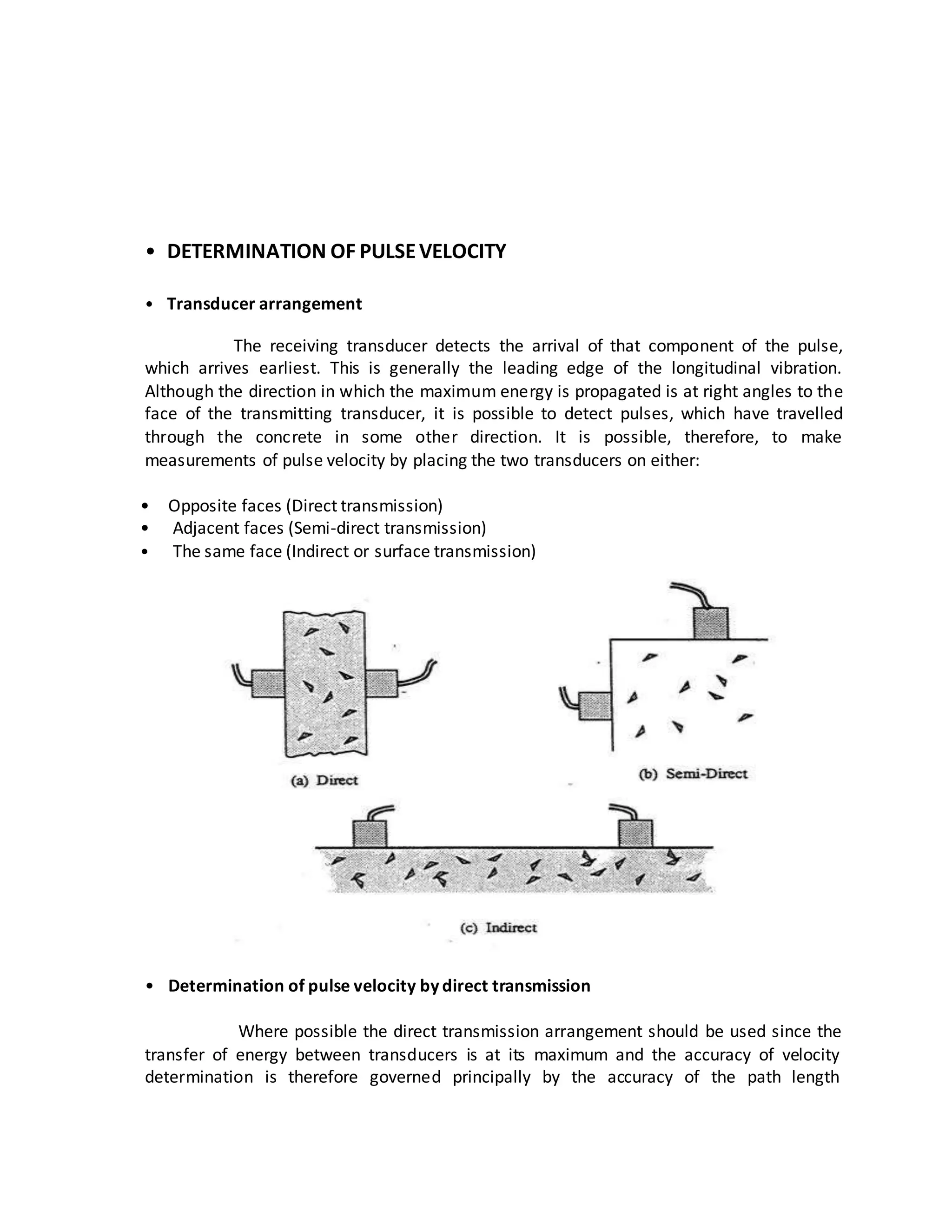
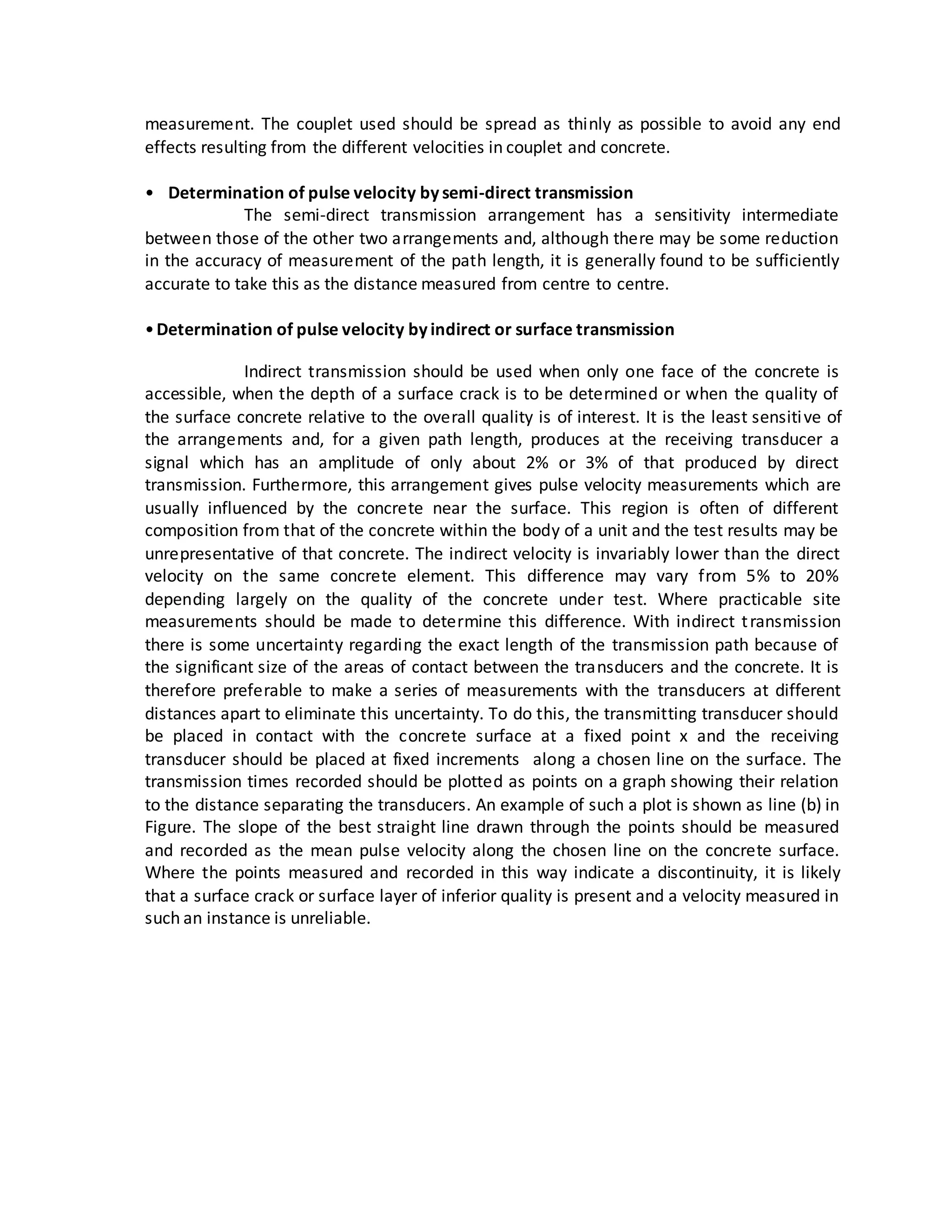
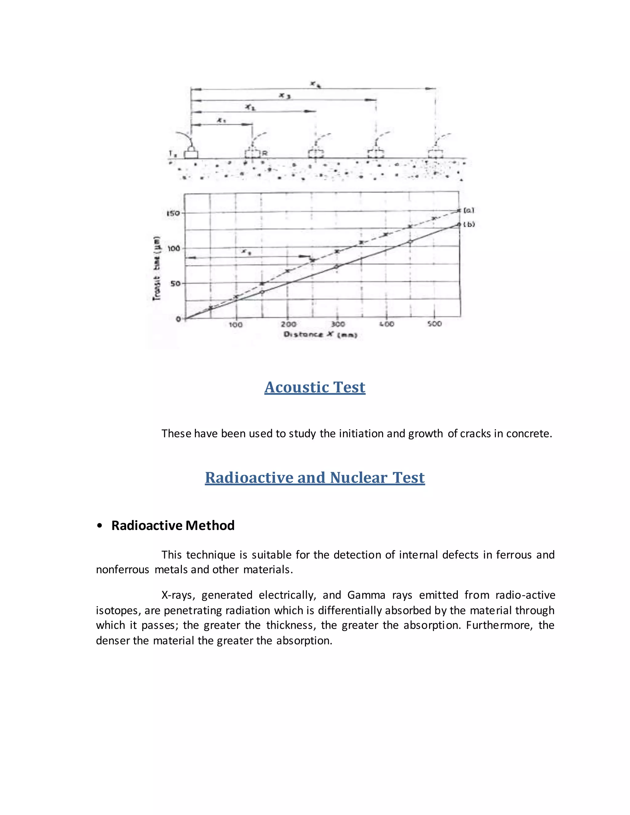

This document summarizes several non-destructive testing methods for concrete, including: - Rebound hammer testing, which measures surface hardness to estimate strength. Factors like surface smoothness and moisture affect results. - Ultrasonic pulse velocity testing, which times pulse transmission through concrete to determine strength. Transducers can be placed on different faces. - Penetration and pull-out tests, which measure hardness by probe penetration depth or pull-out force, respectively, and correlate to strength. Surface damage occurs. - Acoustic, radioactive, and nuclear methods have also been used to study crack initiation and location defects, though radioactive techniques risk safety issues.


