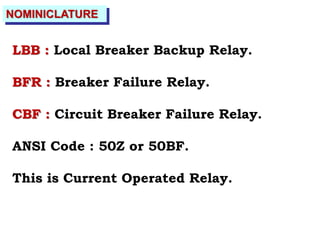
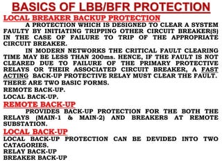
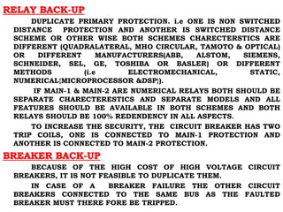
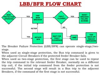
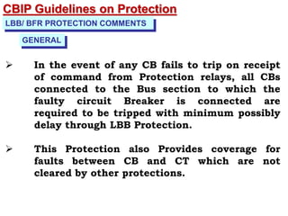
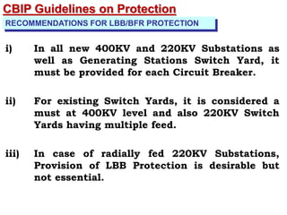
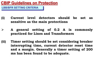
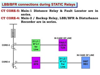
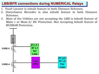
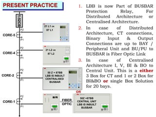
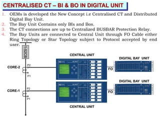
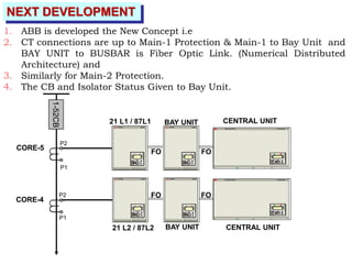
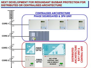
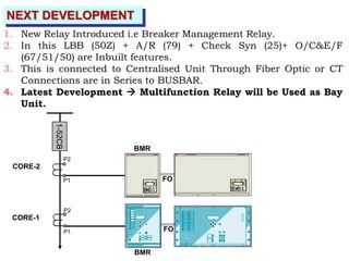
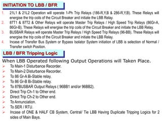
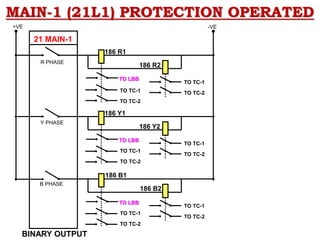
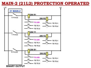
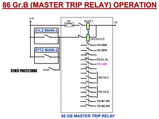
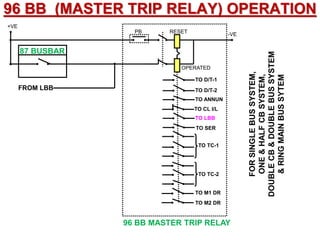
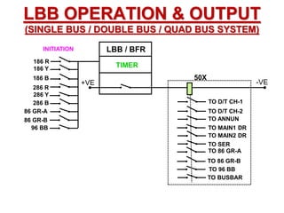
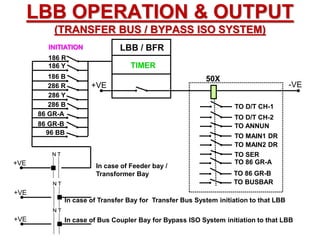
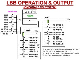
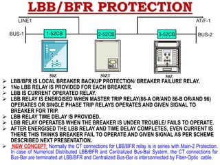
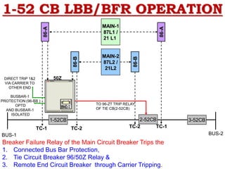
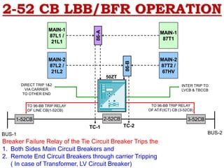
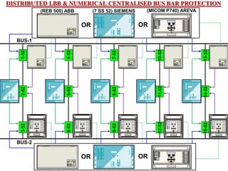
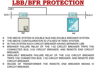
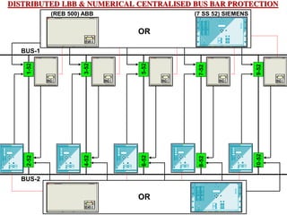
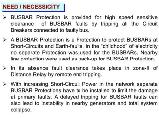
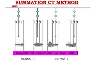
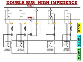
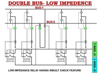
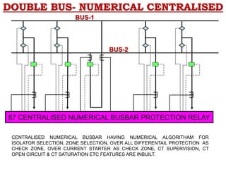
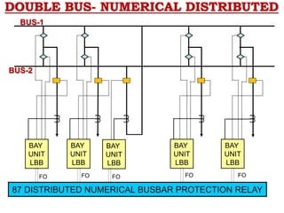
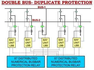
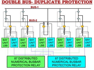
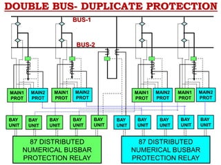
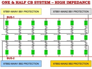
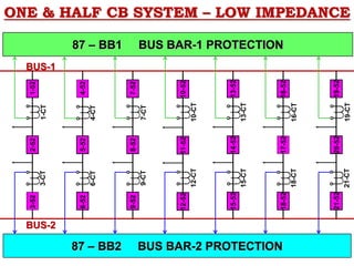
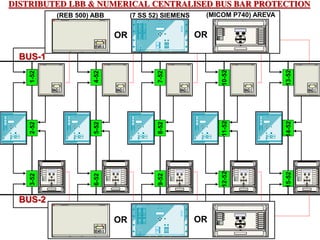
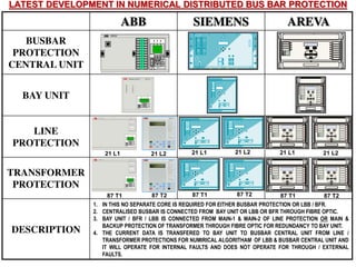
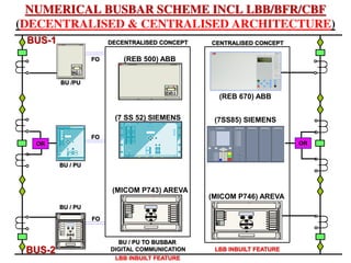
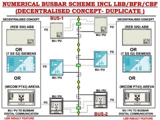
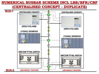
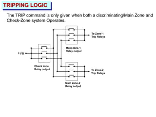
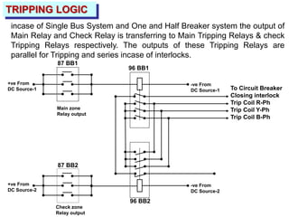
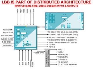
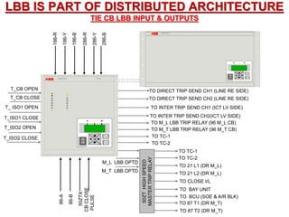
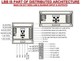
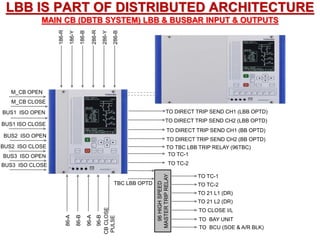
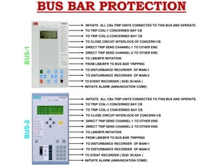
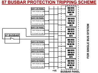
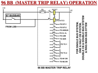
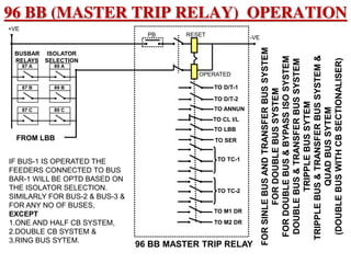
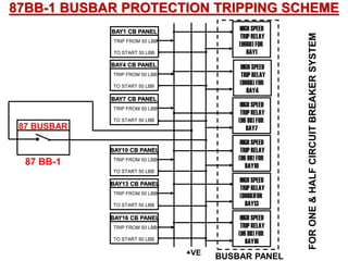
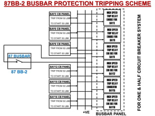
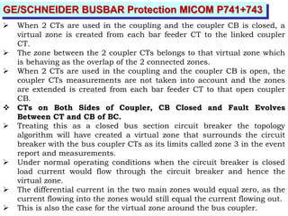
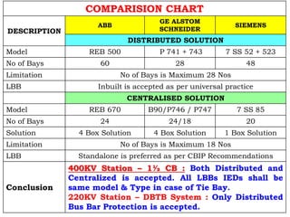
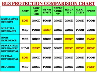
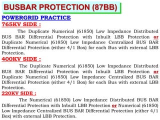
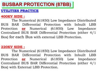
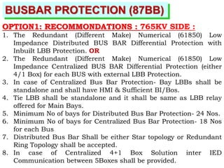
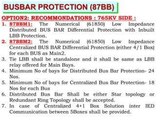
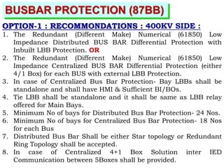
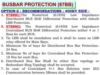
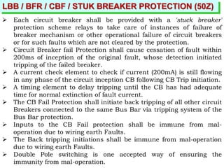
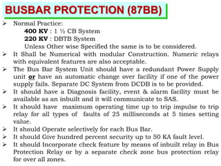
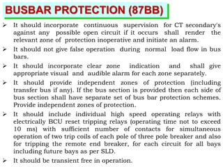
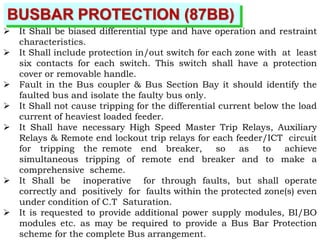
PREPARED BY
GOPALA KRISHNA PALEPU
gkpalepu@gmail.com,
Mobile:9440336984
LBB & BUS BAR
PROTECTION
GOPALA KRISHNA PALEPU
APTRANSCO
gkpalepu@gmail.com,
Mobile:9440336984
NOMINICLATURE
LBB : Local Breaker Backup Relay.
BFR : Breaker Failure Relay.
CBF : Circuit Breaker Failure Relay.
ANSI Code : 50Z or 50BF.
This is Current Operated Relay.
BASICS OF LBB/BFR PROTECTION
LOCAL BREAKER BACKUP PROTECTION
A PROTECTION WHICH IS DESIGNED TO CLEAR A SYSTEM
FAULTY BY INITIATING TRIPPING OTHER CIRCUIT BREAKER(S)
IN THE CASE OF FAILURE TO TRIP OF THE APPROPRIATE
CIRCUIT BREAKER.
IN MODERN NETWORKS THE CRITICAL FAULT CLEARING
TIME MAY BE LESS THAN 200ms. HENCE, IF THE FAULT IS NOT
CLEARED DUE TO FAILURE OF THE PRIMARY PROTECTIVE
RELAYS OR THEIR ASSOCIATED CIRCUIT BREAKER, A FAST
ACTING BACK-UP PROTECTIVE RELAY MUST CLEAR THE FAULT.
THERE ARE TWO BASIC FORMS.
REMOTE BACK-UP.
LOCAL BACK-UP.
REMOTE BACK-UP
PROVIDES BACK-UP PROTECTION FOR THE BOTH THE
RELAYS (MAIN-1 & MAIN-2) AND BREAKERS AT REMOTE
SUBSTATION.
LOCAL BACK-UP
LOCAL BACK-UP PROTECTION CAN BE DEVIDED INTO TWO
CATAGORIES.
RELAY BACK-UP
BREAKER BACK-UP
RELAY BACK-UP
DUPLICATE PRIMARY PROTECTION. i.e ONE IS NON SWITCHED
DISTANCE PROTECTION AND ANOTHER IS SWITCHED DISTANCE
SCHEME OR OTHER WISE BOTH SCHEMES CHARECTERSTICS ARE
DIFFERENT (QUADRALATERAL, MHO CIRCULAR, TAMOTO & OPTICAL)
OR DIFFERENT MANUFACTURERS(ABB, ALSTOM, SIEMENS,
SCHNEIDER, SEL, GE, TOSHIBA OR BASLER) OR DIFFERENT
METHODS (i.e ELECTROMECHANICAL, STATIC,
NUMERICAL{MICROPROCESSOR &DSP}).
IF MAIN-1 & MAIN-2 ARE NUMERICAL RELAYS BOTH SHOULD BE
SEPARATE CHARECTERESTICS AND SEPARATE MODELS AND ALL
FEATURES SHOULD BE AVAILABLE IN BOTH SCHEMES AND BOTH
RELAYS SHOULD BE 100% REDENDENCY IN ALL ASPECTS.
TO INCREASE THE SECURITY, THE CIRCUIT BREAKER HAS TWO
TRIP COILS, ONE IS CONNECTED TO MAIN-1 PROTECTION AND
ANOTHER IS CONNECTED TO MAIN-2 PROTECTION.
BREAKER BACK-UP
BECAUSE OF THE HIGH COST OF HIGH VOLTAGE CIRCUIT
BREAKERS, IT IS NOT FEASIBLE TO DUPLICATE THEM.
IN CASE OF A BREAKER FAILURE THE OTHER CIRCUIT
BREAKERS CONNECTED TO THE SAME BUS AS THE FAULTED
BREAKER MUST THERE FORE BE TRIPPED.
LBB/BFR FLOW CHART
MAIN
PROTECTION
OPERATED
YES
YES
TRIP
MAIN
BREAKER
INITIATE
BFR
WAIT FOR
FAULT
CLEARENCE
AND
FAULT
CLEARED
YES
NO
RESET
BREAKER
FAILURE
SCHEME
TRIP
BACK-UP/
Adjacent
BREAKERS
The Breaker Failure Protection (LBB/BFR) can operate single-stage/two-
stage.
When used as single-stage protection, the Bus trip command is given to
the adjacent Circuit Breakers if the protected feeder Breaker fails.
When used as two-stage protection, the first stage can be used to repeat
the trip command to the relevant feeder Breaker, normally on a different
trip coil, if the initial trip command from the feeder protection is not
successful. The second stage will result in a Bus trip to the adjacent
Breakers, if the command of the first stage is not successful.
RETRIP
LBB/BFR TIME CO-ORDINATION CHART
FAULT OCCURS
NORMAL
CLEARING
INOPERATIVE
BREAKER
BREAKER
INTURUPTING TIME
PROTECTIVE RELAY
FOR EX: DISTANCE RELAY
NORMAL CLEARING TIME
BREAKER FAILURE RELAY START
MARGIN
RESETTING TIME OF THE
CURRENT MEASURING UNITS
SET TIME OF THE TIME MEASURING UNIT TRIPPING
RELAY
TIME
BACK-UP BREAKER
INTERUPTING TIME
TOTAL CLEARING TIME OF THE BREAKER FAILURE RELAY
MARGIN
MAXIMUM FAULT CLEARING TIME BEFORE SYSTEM INSTABILITY
~30ms ~60ms <12ms
LBB/BFR LOGIC
PHASE L1
PHASE L2/E
PHASE L3
CURRENT INPUTS
~
|||
A/D
CONVERTER
&
I > ISET
I > ISET
PHASE CURRENT SET POINT
EARTH CURRENT SET POINT
&
CIRCUIT BREAKER FAILURE INITIATE
BINARY INPUT
OUT PUT OF DISTANCE RELAY OR
SHORT CIRCUIT CURRENT RELAY
> 1
TIMING/OUTPUT
STAGE
0 1
0 1
TIME STAGE T1
TIME STAGE T2
TIME STAGE T2
SWITCHED OFF
&
&
&
O
> 1
LED
CB FAILURE
INITIATE
LED
TRIP T2
RELAY
ALARM T1
RELAY
LED
TRIP T1
RELAY
LED
(PHASE START)
LED
(EARTH START)
ALARM RELAY
(PHASE START)
ALARM RELAY
(EARTH START)
CBIP Guidelines on Protection
LBB/ BFR PROTECTION COMMENTS
 In the event of any CB fails to trip on receipt
of command from Protection relays, all CBs
connected to the Bus section to which the
faulty circuit Breaker is connected are
required to be tripped with minimum possibly
delay through LBB Protection.
 This Protection also Provides coverage for
faults between CB and CT which are not
cleared by other protections.
GENERAL
RECOMMENDATIONS FOR LBB/BFR PROTECTION
i) In all new 400KV and 220KV Substations as
well as Generating Stations Switch Yard, it
must be provided for each Circuit Breaker.
ii) For existing Switch Yards, it is considered a
must at 400KV level and also 220KV Switch
Yards having multiple feed.
iii) In case of radially fed 220KV Substations,
Provision of LBB Protection is desirable but
not essential.
CBIP Guidelines on Protection
LBB/BFR REQUIREMENTS
i) Have Short Operation and Drop off times.
ii) Have 3 Phase Current elements with facility for Phase
wise initiation.
iii) have current setting range such that these can be set
minimum 200mA for Line and 50mA for generators (for
1A CT for secondary).
iv) Have one common associated timer with adjustable
setting.
REQUIREMENTS OF CIRCUIT BREAKERS
 Operating Time
 Breaking Capacity
 Stuck Breaker Probability
 Operating Sequence / Duty cycle
CBIP Guidelines on Protection
LBB/BFR OPERATION
 The Breaker Failure Protection (LBB/BFR) can operate
single-stage/two-stage.
 When used as single-stage protection, the Bus trip
command is given to the adjacent Circuit Breakers if
the protected feeder Breaker fails.
 When used as two-stage protection, the first stage can
be used to repeat the trip command to the relevant
feeder Breaker, normally on a different trip coil, if the
initial trip command from the feeder protection is not
successful. The second stage will result in a Bus trip
to the adjacent Breakers, if the command of the first
stage is not successful. (This is More recommended)
CBIP Guidelines on Protection
LBB/BFR SPECIAL COMMENTS
(i) The relay is separate for each breaker and is to be
connected in the secondary circuit of the CTs
associated with that particular breaker.
(ii) For line breakers, direct tripping of remote end
breaker(s) should be arranged on operation of
LBB protection.
For transformer breakers, direct tripping of
breaker(s) on the other side of the transformer
should be arranged on operation of LBB
protection
(iii) For lines employing single phase auto reclosing,
the LBB relays should be started on a single
phase basis from the trip relays.
CBIP Guidelines on Protection
LBB/BFR SPECIAL COMMENTS
(iv) The CT sec core may be separate core, if available.
Other wise it shall be Clubbed (in series) with Main-1
or Main-2 protection.
(v) It is considered a good practice to have DC circuits of
Gr.A and Gr. B protections and relay independent.
(vi) LBB cannot operate without proper initiation. It is
good practice to provide redundant trip output and
breaker fail input where other forms of redundancy
does not exist.
(vii) Separation should be maintained between protective
relay and CB trip coil DC circuit so that short circuit
or blown fuse in the CB circuit will not prevent the
protective relay from energizing the LBB scheme.
CBIP Guidelines on Protection
LBB/BFR SPECIAL COMMENTS
(viii) In addition to other fault sensing relays the LBB relay
should be initiated by Bus bar protection, since failure
of CB to clear a bus fault would result in the loss of
entire station if BFP relay is not initiated
(ix) Tripping logic of the bus bar protection scheme shall
be used for LBB protection also.
(x) For breaker-fail relaying for low energy faults like
buchholz operation, special considerations may have
to be given to ensure proper scheme operation by
using C.B. contact logic in addition to current
detectors.
CBIP Guidelines on Protection
LBB/BFR SETTING CRITERIA
(i) Current level detectors should be set as
sensitive as the main protections
 A general setting of 0.2 A is commonly
practiced for Lines and Transformers
(ii) Timer setting should be set considering breaker
interrupting time, current detector reset time
and a margin. Generally a timer setting of 200
ms has been found to be adequate.
CBIP Guidelines on Protection
GOPALA KRISHNA PALEPU
APTRANSCO
gkpalepu@gmail.com,
Mobile:9440336984
LBB/BFR connections during STATIC Relays
CT CORE-5: Main-1 Distance Relay & Fault Locator are in
series.
CT CORE-4: Main-2 / Backup Relay, LBB/BFR & Disturbance
Recorder are in series.
CORE-5
CORE-4
IN CASE OF LINE
IN CASE OF LINE
1-52CB
FAULT
LOCA-
TOR
21 L1 /
87 L1
for
Line
LBB
BFR
21 L2 /
87 L2
For
Line
DIST
REC
P2
P1
P2
P1
LBB/BFR connections during NUMERICAL Relays
1. Fault Locator is inbuilt feature in both Distance Schemes.
2. Disturbance Recorder is also inbuilt feature in both Distance
Schemes.
3. Most of the Utilities are not accepting the LBB is Inbuilt feature of
Main-1 or Main-2/ BU Protection. But Accepting Inbuilt feature of
BUSBAR Protection.
CORE-5
CORE-4
P2
P1
P2
P1
1-52CB
21 L1 /
87 L1
for
Line
LBB
BFR
21 L2 /
87 L2
For
Line
PRESENT PRACTICE 1. LBB is now Part of BUSBAR
Protection Relay, For
Distributed Architecture or
Centralised Architecture.
2. In case of Distributed
Architecture, CT connections,
Binary Input & Output
Connections are up to BAY /
Peripheral Unit and BU/PU to
BUSBAR is Fiber Optic Link
3. In case of Centralised
Architecture I, V, BI & BO to
Central Unit. This is a either
3 Box for CT and 1 or 2 Box for
BI&BO or single Box Solution
for 20 bays.
CORE-5
CORE-4
CORE-1 FIBER
OPTIC
OR
CORE-2
C
E
50Z +87BB
CENTRAL UNIT
LBB IS INBUILT
BUSBAR
ABB Network Partner AG
21 L1 OR
87 L1
C
E
ABB Network Partner AG REL531
21 L2 OR
87 L2
50 Z + 87BB
LBB IS INBUILT
CENTRALISED
BUSBAR
1
2
3
4
5
6
7
8
9
10
11
12
13
14
15
16
ABB Network Partner AG REL 316*4
C
E
BU/PU
1-52CB
P2
P1
P2
P1
P2
P1
P2
P1
1. OEMs is developed the New Concept i.e Centralised CT and Distributed
Digital Bay Unit.
2. The Bay Unit Contains only BIs and Bos.
3. The CT connections are up to Centralized BUSBAR Protection Relay.
4. The Bay Units are connected to Central Unit through FO Cable either
Ring Topology or Star Topology subject to Protocol accepted by end
user.
CORE-2
CORE-1
FO
DIGITAL BAY UNIT
CENTRAL UNIT
1-52CB
P2
P1
P2
P1
CENTRALISED CT – BI & BO IN DIGITAL UNIT
FO
DIGITAL BAY UNIT
CENTRAL UNIT
1. ABB is developed the New Concept i.e
2. CT connections are up to Main-1 Protection & Main-1 to Bay Unit and
BAY UNIT to BUSBAR is Fiber Optic Link. (Numerical Distributed
Architecture) and
3. Similarly for Main-2 Protection.
4. The CB and Isolator Status Given to Bay Unit.
CORE-5
21 L1 / 87L1
CORE-4
21 L2 / 87L2
FO
FO
FO
FO
BAY UNIT
BAY UNIT
CENTRAL UNIT
CENTRAL UNIT
1-52CB
P2
P1
P2
P1
NEXT DEVELOPMENT
CORE-1
CORE-2
CORE-2 FIBER
OPTIC
CORE-1
C
E
50Z +87BB
CENTRAL UNIT
LBB IS INBUILT
BUSBAR
ABB Network Partner AG
BU/PU
NEXT DEVELOPMENT FOR REDUNDANT BUSBAR PROTECTION FOR
DISTRIBUTED OR CENTRALISED ARCHITECTURE
FIBER
OPTIC
1-52CB
1
2
3
4
5
6
7
8
9
10
11
12
13
14
15
16
ABB Network Partner AG REL 316*4
C
E
P2
P1
P2
P1
P2
P1
P2
P1
DISTRIBUTED
ARCHETECTURE
BAY
UNIT
&
CENTRAL
UNIT
CENTRALISED ARCHETECTURE
PHASE SEGREGATED & 3PH UNIT
NEXT DEVELOPMENT
CORE-2
CORE-1
1. New Relay Introduced i.e Breaker Management Relay.
2. In this LBB (50Z) + A/R (79) + Check Syn (25)+ O/C&E/F
(67/51/50) are Inbuilt features.
3. This is connected to Centralised Unit Through Fiber Optic or CT
Connections are in Series to BUSBAR.
4. Latest Development  Multifunction Relay will be Used as Bay
Unit.
P2
P1
P2
P1
BMR
FO
BMR
1-52CB
FO
GOPALA KRISHNA PALEPU
APTRANSCO
gkpalepu@gmail.com,
Mobile:9440336984
INITIATION TO LBB / BFR
1. 21L1 & 21L2 Operation will operate 1-Ph Trip Relays (186-R,Y,B & 286-R,Y,B). These Relays will
energise the trip coils of the Circuit Breaker and initiate the LBB Relay.
2. 87T1 & 87T2 & Other Relays will operate Master Trip Relays / High Speed Trip Relays (86Gr-A,
86Gr-B). These Relays will energise the trip coils of the Circuit Breaker and initiate the LBB Relay.
3. BUSBAR Relays will operate Master Trip Relays / High Speed Trip Relays (96-BB). These Relays will
energise the trip coils of the Circuit Breaker and initiate the LBB Relay.
4. Incase of Transfer Bus System or Bypass Isolator System initiation of LBB is selection of Normal /
Transfer switch Position.
LBB / BFR Tripping Logic
When LBB Operated following Output Operations will Taken Place.
 To Main-1 Disturbance Recorder.
 To Main-2 Disturbance Recorder.
 To 86 Gr-A Bi-Stable relay.
 To 86 Gr-B Bi-Stable relay.
 To 87BUSBAR Output Relays ( 96BB1 and/or 96BB2).
 Direct Trip Ch-1 to Other end.
 Direct Trip Ch-2 to Other end.
 To Annunciation.
 To SER / RTU.
 Incase of ONE & HALF CB System, Central/ Tie LBB Having Duplicate Tripping Logics for 2
sides of Main Bays.
MAIN-1 (21L1) PROTECTION OPERATED
21 MAIN-1
BINARY OUTPUT
TO LBB
TO TC-1
TO TC-2
TO LBB
TO TC-1
TO TC-2
TO TC-1
TO TC-2
TO TC-1
TO TC-2
TO LBB
TO TC-1
TO TC-2
TO TC-1
TO TC-2
+VE -VE
R PHASE
Y PHASE
B PHASE
186 R1
186 R2
186 Y1
186 Y2
186 B1
186 B2
MAIN-2 (21L2) PROTECTION OPERATED
21 MAIN-2
BINARY OUTPUT
TO LBB
TO TC-1
TO TC-2
TO LBB
TO TC-1
TO TC-2
TO TC-1
TO TC-2
TO TC-1
TO TC-2
TO LBB
TO TC-1
TO TC-2
TO TC-1
TO TC-2
+VE -VE
R PHASE
Y PHASE
B PHASE
286 R1
286 R2
286 Y1
286 Y2
286 B1
286 B2
86 Gr.A (MASTER TRIP RELAY) OPERATION
21L1:MAIN-1
TO ANN
+VE
-VE
RESET
OPERATED
PB
TO CL I/L
TO LBB
TO TC-1
TO TC-2
TO M1 DR
TO M2 DR
TO SER
86 GA MASTER TRIP RELAY
OTHER PROTECTIONS
87T1:MAIN-1
86 Gr.B (MASTER TRIP RELAY) OPERATION
21L2:MAIN-2
TO ANN
+VE
-VE
RESET
OPERATED
PB
TO CL I/L
TO LBB
TO TC-1
TO TC-2
TO M1 DR
TO M2 DR
TO SER
86 GB MASTER TRIP RELAY
OTHER PROTECTIONS
87T2:MAIN-2
96 BB (MASTER TRIP RELAY) OPERATION
87 BUSBAR
TO D/T-1
+VE
-VE
RESET
OPERATED
PB
TO CL I/L
TO LBB
TO TC-1
TO TC-2
TO M1 DR
TO M2 DR
TO D/T-2
96 BB MASTER TRIP RELAY
TO ANNUN
TO SER
FROM LBB
FOR
SINGLE
BUS
SYSTEM,
ONE
&
HALF
CB
SYSTEM,
DOUBLE
CB
&
DOUBLE
BUS
SYSTEM
&
RING
MAIN
BUS
SYTEM
LBB OPERATION & OUTPUT
(SINGLE BUS / DOUBLE BUS / QUAD BUS SYSTEM)
INITIATION
186 R
186 Y
186 B
286 R
286 Y
286 B
86 GR-A
86 GR-B
96 BB
+VE
TO D/T CH-1
TO D/T CH-2
TO ANNUN
TO MAIN1 DR
TO MAIN2 DR
TO SER
TO 86 GR-A
TO 86 GR-B
TO BUSBAR
-VE
50X
LBB / BFR
TIMER
TO 96 BB
LBB OPERATION & OUTPUT
(TRANSFER BUS / BYPASS ISO SYSTEM)
INITIATION
186 R
186 Y
186 B
286 R
286 Y
286 B
86 GR-A
86 GR-B
96 BB
+VE
TO D/T CH-1
TO D/T CH-2
TO ANNUN
TO MAIN1 DR
TO MAIN2 DR
TO SER
TO 86 GR-A
TO 86 GR-B
TO BUSBAR
-VE
50X
LBB / BFR
TIMER
+VE
N T
. In case of Feeder bay /
Transformer Bay
+VE
N T
.In case of Transfer Bay for Transfer Bus System initiation to that LBB
In case of Bus Coupler Bay for Bypass ISO System initiation to that LBB
+VE
N T
.
LBB OPERATION & OUTPUT
(ONE&HALF CB SYSTEM)
INITIATION
186 R
186 Y
186 B
286 R
286 Y
286 B
86 GR-A
86 GR-B
96 BB
+VE
TO D/T CH-1
TO D/T CH-2
TO ANNUN
TO MAIN1 DR
TO MAIN2 DR
TO SER
TO 86 GR-A
TO 86 GR-B
TO BUSBAR
-VE
50X1
LBB / BFR
TIMER
TO D/T CH-1
TO D/T CH-2
TO ANNUN
TO MAIN1 DR
TO MAIN2 DR
TO SER
TO 86 GR-A
TO 86 GR-B
TO BUSBAR
-VE
50X2
IN THIS 2 NOS TRIPPING AUXILIARY RELAYS
PROVIDED FOR MAIN CB & TIE CB.
IN CASE OF TIE LBB, ONE FOR BUS-1 MAIN
CB & OTHER FOR BUS-2 MAIN CB.
LBB/BFR PROTECTION
2-52CB 3-52CB
BUS-1 BUS-2
LINE1 AT/F-1
50Z 50Z
 LBB/BFR IS LOCAL BREAKER BACKUP PROTECTION/ BREAKER FAILURE RELAY.
 1No LBB RELAY IS PROVIDED FOR EACH BREAKER.
 LBB IS CURRENT OPERATED RELAY.
 LBB RELAY IS ENERGISED WHEN MASTER TRIP RELAY(86-A OR/AND 86-B OR/AND 96)
OPERATES OR SINGLE PHASE TRIP RELAYS OPERATES AND GIVEN SIGNAL TO
BREAKER FOR TRIP.
 LBB RELAY TIME DELAY IS PROVIDED.
 LBB RELAY OPERATES WHEN THE BREAKER IS UNDER TROUBLE/ FAILS TO OPERATE.
 AFTER ENERGISED THE LBB RELAY AND TIME DELAY COMPLETES, EVEN CURRENT IS
THERE THIS THINKS BREAKER FAIL TO OPERATE AND GIVEN SIGNAL AS PER SCHEME
DESCRIBED NEXT PRESENTATION.
 NEW CONCEPT: Normally the CT connections for LBB/BFR relay is in series with Main-2 Protection.
In case of Numerical Distributed LBB/BFR and Centralized Bus-Bar System, the CT connections for
Bus-Bar are terminated at LBB/BFR and Centralized Bus-Bar is interconnected by Fiber-Optic cable.
50ZT
1-52CB
1-52 CB LBB/BFR OPERATION
BUS-1 BUS-2
1-52CB 3-52CB
2-52CB
86-A
86-B
MAIN-1
87L1 /
21 L1
MAIN-2
87L2 /
21L2
86-A
86-B
TC-1 TC-2
BUSBAR-1
PROTECTION (96-BB )
OPTD
AND BUSBAR-1
ISOLATED
DIRECT TRIP 1&2
VIA CARRIER TO
OTHER END
TC-1
TC-2
50Z
TO 96-ZT TRIP RELAY
OF TIE CB(2-52CB)
Breaker Failure Relay of the Main Circuit Breaker Trips the
1. Connected Bus Bar Protection,
2. Tie Circuit Breaker 96/50Z Relay &
3. Remote End Circuit Breaker through Carrier Tripping.
2-52 CB LBB/BFR OPERATION
BUS-1 BUS-2
1-52CB 3-52CB
2-52CB
MAIN-1
87L1 /
21L1
MAIN-2
87L2 /
21L2
86-A
86-B
TC-1 TC-2
MAIN-1
87T1
MAIN-2
87T2 /
67HV
TO 96-BB TRIP RELAY
OF LINE CB(1-52CB)
DIRECT TRIP 1&2
VIA CARRIER
TO OTHER END
TO 96-BB TRIP RELAY
OF AT/F(ICT) CB (3-52CB)
INTER TRIP TO
LVCB & TBCCB
50ZT
Breaker Failure Relay of the Tie Circuit Breaker Trips the
1. Both Sides Main Circuit Breakers and
2. Remote End Circuit Breakers through carrier Tripping
( In case of Transformer, LV Circuit Breaker)
3-52 CB LBB/BFR OPERATION
BUS-1 BUS-2
1-52CB 3-52CB
2-52CB
86-A
86-B
MAIN-1
87T1
MAIN-2
87T2
67 HV
86-A
86-B
TC-1 TC-2 TC-1
TC-2
BUSBAR-2 (96 BB)
PROTECTION OPTD
AND BUSBAR-2
ISOLATED
INTER TRIP TO
LV CB & TBC CB
50Z
TO 96-ZT TRIP RELAY
OF TIE CB(2-52CB)
Breaker Failure Relay of the Main Circuit Breaker Trips the
1. Connected Bus Bar Protection
2. Tie Circuit Breaker 96/50Z Relay &
3. Remote End Circuit Breaker ( In case of ICT, LV CB)
DISTRIBUTED LBB & NUMERICAL CENTRALISED BUS BAR PROTECTION
BUS-2
BUS-1
1-52
2-52
3-52
4-52
5-52
6-52
7-52
8-52
9-52
10-52
11-52
12-52
13-52
14-52
15-52
OR OR
(REB 500) ABB (7 SS 52) SIEMENS (MICOM P740) AREVA
OR OR
LBB/BFR PROTECTION
1-52CB 2-52CB
BUS-1 BUS-2
LINE1
50Z 50Z
 THE ABOVE SYSTEM IS DOUBLE BUS AND DOUBLE BREAKER SYSTEM.
 THE ABOVE CONFIGUARATION IS UTILISED IN 765KV SYSTEM.
 IN THIS SYSTEM EACH CIRCUIT BREAKER HAVING SEPARATE LBB.
 BREAKER FAILURE RELAY OF THE 1-52 CIRCUIT BREAKER TRIPS THE
CONNECTED BUS, 2-52 CIRCUIT BREAKER, AND REMOTE END CIRCUIT
BREAKER.
 SIMILARLY BREAKER FAILURE RELAY OF THE 2-52 CIRCUIT BREAKER
TRIPS THE CONNECTED BUS, 1-52 CIRCUIT BREAKER, AND REMOTE END
CIRCUIT BREAKER.
 INCASE OF TRANSFORMER THE REMOTE END BREAKER MEANS IV
CIRCUIT BREAKER.
DISTRIBUTED LBB & NUMERICAL CENTRALISED BUS BAR PROTECTION
BUS-2
BUS-1
1-52
2-52
3-52
4-52
5-52
6-52
7-52
8-52
9-52
10-52
OR
(REB 500) ABB (7 SS 52) SIEMENS
OR
GOPALA KRISHNA PALEPU
APTRANSCO
gkpalepu@gmail.com,
Mobile:9440336984
NEED / NECESSICITY
 BUSBAR Protection is provided for high speed sensitive
clearance of BUSBAR faults by tripping all the Circuit
Breakers connected to faulty bus.
 A BUSBAR Protection is a Protection to protect BUSBARs at
Short-Circuits and Earth-faults. In the “childhood” of electricity
no separate Protection was used for the BUSBARs. Nearby
line protection were used as back-up for BUSBAR Protection.
 In its absence fault clearance takes place in zone-II of
Distance Relay by remote end tripping.
 With increasing Short-Circuit Power in the network separate
BUSBAR Protections have to be installed to limit the damage
at primary faults. A delayed tripping for BUSBAR faults can
also lead to instability in nearby generators and total system
collapse.
NEED / NECESSICITY
 The earliest form of BUS Protection was that
provided by the relays of circuits (i.e. Lines,
Transformers, Reactors & Capacitor Banks) over
which current was supplied to a BUS. In other
words the BUS was included within the back-up
zone of these relays. This method was relatively
slow speed, and loads tapped from the lines would
be interrupted unnecessarily, but it was otherwise
effective. Some preferred this method to one in
which the inadvertent operation of a single relay
would trip all the connections to the BUS.
 This Means Slow And Unselective Tripping And
Wide Spread Black Out.
EFFECT OF DELAYED CLEARENCE
 Greater damage at fault point.
 Indirect shock to connected equipments like shafts of
Generator and windings of Transformer.
PRINCIPLE OF OPERATION
 The Principle of Operation of Bus bar protection is
Kirchoff’s Current Law. i.e. Sum of the Currents
Entering in to the Node is equal to Sum of the
Currents Leaving the node. Here Node Means
BUSBAR.
CAUSES OF BUS ZONE FAULTS
 Deterioration of Insulating Material.
 Flashover of insulators due to lightning or
System Over Voltages.
 Wrong application of /or failure to remove
temporary earth connections.
 Short circuits caused by birds, monkeys,
vermin and the like.
 Short circuits caused by construction
machinery.
BASICS OF BUS BAR PROTECTION
BASIC THEORY
EXTERNAL FAULT
KIRCHOFF’s CURENT LAW STATES THAT THE SUM OF THE CURRENTS ENTERING A GIVEN NODE MUST BE EQUAL
TO THE CURRENTS LEAVING THAT NODE
I6
I4
I2
I5
I3
I1
IF
IF= I6= I1+I2+I3+I4+I5
INTERNAL FAULT
I6
I4
I2
I5
I3
I1
IF
IF= I1+I2+I3+I4+I5+I6
RECOMMENDATIONS
 Must have as short tripping time as possible.
 Must be able to detect internal faults.
 Must be absolutely stable at external faults. External faults are
much more common than internal faults. The magnitude of
external faults can be equal to the stations maximum breaking
capacity, while the function currents can go down to
approximately 2% of the same. The stability factor there fore
needs to be at least 50 times i.e. 20. CT-saturation at external
faults must not lead to mal-operation of the BUSBAR
Protection.
 Must be able to detect and trip only the faulty part of the
BUSBAR system.
 Must be secure against mal-operation due to auxiliary contact
failure, human mistakes and faults in the secondary circuits
etc.
TYPES OF BUSBAR PROTECTION SCHEMES
 HIGH IMPEDENCE BUSBAR PROTECTION:
High Impedance Differential Protection has traditionally been provided by
Electromechanical Relays and associated stabilising resistances connected
across the Current Transformer secondary bus wires of the Protected zone,
i.e. the Measuring Circuit comprises a High impedance stabilising Resistor
(Metrosil) connected across the circulating current arrangement of all the
CT’s in parallel. The resulting Scheme is economical, simple in concept and
easily extendable to cover additional circuits. It has an added advantage that
low fault current settings can be achieved whilst retaining through fault
stability. Application of this type of scheme can however sometimes be
limited by the need for CTs on each circuit to be of the same ratio and by the
knee point voltage required to achieve fast operating times. The Value of
Stabilising Resistor chosen such that the voltage drop across the relay circuit
is insufficient to operate the relay for faults outside the protection zone.
The High-impedance protection scheme, on the other hand, is a good
Solution for single BUSBAR arrangements, 1 ½ breaker systems or ring
BUSBARS, providing that appropriate dedicated CT cores are available For
this use alone.
TYPES OF BUSBAR PROTECTION SCHEMES
 MEDIUM/MODERATE IMPEDENCE BUSBAR PROTN:
This is effectively combination of the normal plain
circulating current High-Impedance and Stabilised
percentage biased differential scheme. This relay
acts as Medium Impedance Protection during
internal faults & but Low Impedance Protection
during load and external faults.
Although heavy through fault currents may produce
a different current that exceeds the differential pick-
up setting, stabilizing current prevents tripping. The
requirements made on the primary CT’s are
subsequently less stringent than for a simple High-
Impedance Scheme.
LOW IMPEDANCE PROTECTION
 PHASE COMPARISION BUSBAR PROTECTION:
This operates on the principle that any BUSBAR fault will be
characterised by all current flows towards the protected BUSBARS
and phase coincidence and is checked for positive and negative
half cycles. In addition the non coincidence is used for as a
blocking signal.
However under low fault level conditions, it is possible for some
load flow to continue. To prevent this from stabilising the
Protection, a fault load current of Highest rated outgoing circuit is
normally selected i.e. pick-up level is set above the load current.
The differential current can also be included in the phase
comparison , there by further improving stability.
The Main advantage of this scheme is that, it is not necessary for
the current transformers on each circuit to be equal ratio. Also the
current transformers may be lower output than those required for
High-Impedance Schemes.
LOW IMPEDANCE BUSBAR PROTECTION
 PERCENTAGE BIASED DIFFERENTIAL PROTECTION:
This Protection is known as current comparison with current restraint,
biased or percentage differential relaying. The operating current is the
Phasor sum of all feeder currents and the restraint current is the
arithmetic sum. A trip command is given when operating current is
greater than its pickup level and the stabilising factor the ratio of
operating current to restraint current.
in case of CTs ratios differ, the currents have to be balanced by using
interposing CTs (Aux ratio matching CTs). In this load bias take care for
any matching errors.
where as High-Impedance protection the scheme is inherently stable
during CT saturation, in this scheme special measures must be taken
to ensure the protection remains stable during CT saturation. In this
scheme check feature can be included.
This type incorporates a stabilising resistor to ensure through fault
stability at high fault levels. This can limit the minimum size of current
transformer that will be required to ensure high speed performance.
VOLTAGE DIFFERENTIAL RELAY WITH LINEAR COUPLERS
The problem of CT saturation is eliminated at its source by air-core CTs
called linear couplers. These CTs are like bushing CTs but they have no
iron in their core, and the number of secondary turns is much greater.
The secondary-excitation characteristic of these CTs is a straight line
having a slope of about 5 volts per 1000 ampere-turns.
Contrasted with conventional CTs, linear couplers may be operated
without damage with their secondaries open-circuited. In fact, very little
current can be drawn from the secondary, because so much of the
primary magneto-motive force is consumed in magnetizing the core.
The linear couplers are connected in a series of all CTs & to Voltage-
Differential circuit. For normal load or external-fault conditions, the sum
of the voltages induced in the secondaries is zero, except for the very
small effects of manufacturing tolerances, and there is practically no
tendency for current to flow in the Differential Relay.
When a BUS fault occurs, the Voltages of the CTs in all the source circuits
add to cause current to flow through all the secondaries and the coil of
the Differential Relay. The Differential Relay, necessarily requiring very
little energy to operate, will provide high-speed Protection for a relatively
small net voltage in the Differential Circuit.
SUMMATION CTs METHOD
In practical application of the schemes, Summation
Current Transformers (one per main set of CTs) are normally
used. These summation CTs have a tapped primary to which
the three phases of the Main CTs are connected, the secondary
of the summation CTs providing single-phase output.
The Advantages of summation CTs are.
1. Single Relay is used for all three phases.
2. A Definite bias is available for all types external faults.
3. Lead burden on Main CTs is less, provided these CTs are
located Judiciously.
4. Secondary Cabling is reduced.
5. Aux switch requirement in Double BUSBAR arrangement is
reduced.
The Main Drawbacks are
1. The setting for Various types of faults is different, needing careful
analysis.
2. Bias effect is less for Phase faults than for Earth faults.
NUMERICAL BUSBAR PROTECTION
 In this two Models of BUSBAR Protections are offered.
1. Centralised Architecture.
2. Distributed Architecture.
 The following are the advantages in this Numerical BUSBAR Protection
1. LBB, EFP and other Protections are inbuilt feature.
2. Ratio Matching Transformers are not required. They can be
programmable.
3. Isolator selection is required and these are to be wired to Bay unit as a
binary input & selection relays are not required for zone segregation.
4. One Unit is sufficient, for any no of Zones of BUSBAR Protection.
5. In Distributed Architecture Communication between Bay Unit to Central
Unit is Fiber Optic connection.
6. Check Zone feature like Over-all Differential Protection & Over Current
Starter Protection is in built function. Recently rate of fall of Voltage
function also inbuilt function.
7. Current comparison, CT supervision, CT open circuit & CT Saturation
Detection is also inbuilt feature.
8. Disturbance Recorder and Event Recorders are inbuilt feature.
9. Distributed Architecture is more convenient, it can be accommodated in
respective Bay C&R Panels and very easy for expansion.
Traditionally Two Distinctive Architectures
(CENTRALISED & DECENTRALISED)
• Fits better new installations
• Perceived less reliable
• Slower
52
DAU
52
DAU
52
DAU
CU
copper
fiber
Distributed Bus Protection
52 52 52
CU
copper
Centralized Bus Protection
• Fits better retrofit installations
• Perceived more reliable
• Potentially faster
CHECK ZONE FEATURE
 Mal-operation of BUSBAR Protection can
result in wide spread system failure. It is
therefore considered judicious to monitor its
operation by some form of check relay.
 In case of High Impedance Relay the setting
calculations is quite high and some times low
settings can be adopted. In this factor of
safety is more. This may be possibility for
mal-operation from design point of view. The
provision of a check feature is therefore
purely a measure against mal-operation
caused by external agencies.
CHECK ZONE FEATURE
The ideal check feature should posses the following characteristics:
1. Check feature should be provided by a Relay which is physically different
from the Main Relay.
2. It should pick-up for all types of faults that the Main Protection is capable of
detecting.
3. The check feature should be at least as fast if not faster than Main
Protection for given type of fault.
4. The source which feeds the Check Relay should be Physically Different
from what feeds the Main Protection.
5. The Check feature should operate only for faults within the Main Zone/Zones
of Protection and not for external faults.
6. A separate cores of CTs for Check Relay is added with the ratios same as
for the Main Relay.
7. Check Relay can be connected irrespective of CT isolator selection in case
of Double Bus, Triple Bus & Quad Bus for all circuits, this is called overall
Check zone and in case Single Bus and 1-1/2 CB system same as Main
Relay.
CBIP Guidelines on Protection
SPECIAL COMMENTS
i) DC Supply for Bus Bar protection shall be independent from
feeder.
ii) Faults between CB & CT shall be cleared from one side by
opening of CB on Bus Bar Protection Operation.
iii) However clearing of Fault from other side shall be through
Breaker Failure Protection.
iv) 3–ph trip relays shall be provided for each CB which shall
also initiate LBB/BFR Protection.
v) in case of existing SS where CTs are different ratios, biased
type Differential Protection/ Numerical Bus Bar Protection is
recommended.
vi) Length of secondary leads should be kept as minimum as
possible.
vii) Where lead runs are excessive, an increase in wire size or
use of parallel conductors are meant to reduce lead
resistance.
REQUIREMENTS
i. It shall be 3-ph type and operate selectively for each bus bar section.
ii. It shall operate on Differential Principle and provide independent zones
of protection for each bus.
iii. It shall provide zone indication.
iv. It shall be stable for through fault conditions up to maximum 40KA fault
level.
v. For applications where BUS Differential Protection sensitivity has to be
set below load current, as may be a case with use of concrete
structures, it is recommended that a separate check zone is provided,
other wise separate check zone is not essential. Check zone, if provided,
shall be of High Impedance type.
vi. It shall incorporate continuous supervision for CT secondary against any
possible open circuits. In case of detection of open circuiting of CT
secondary, after a time delay, the effected zone of protection shall be
rendered inoperative and alarm initiated.
vii. It shall be include DC supply supervision.
viii. Include adequate number of high speed tripping relays.
ix. whenever CT switching is involved the scheme shall include necessary
CT switching relays and have provision for CT switching incomplete
alarm.
x. It shall be include IN/OUT switching facility for each zone.
CBIP Guidelines on Protection
 C.T wire supervision relays should be set with a sensitivity such
that they can detect C.T secondary open circuit even in case of
least loaded feeder.
 BUSBAR Differential Protection should have overall sensitivity
above heaviest loaded feeder current unless a separate check
zone has been provided.
 In case where faults currents are expected to be low, the
protection should be sensitive enough to take care of such
expected low fault current.
 In case of voltage operated High Impedance type Protection, the
voltage setting should be above expected voltage developed
across the relay during maximum through fault current condition.
 In case of current operated relays for stability under through
fault condition, external resistance is to be set such that voltage
developed across relay and resistance combination is below the
voltage required for forcing required relay operating current.
SETTING CRITERIA
CBIP Guidelines on Protection
HIGH IMPEDENCE BUSBAR PROTECTION
87BBM1
87BBM2
52 CIRCUIT
BREAKER
TRIP COIL
+ VE
- VE
96 BBM2 : BUSBAR
MAIN2 TRIPPING RELAY
96 BBM1 : BUSBAR
MAIN1 TRIPPING RELAY
A varistor is normally applied
across the relay input terminals
to limit the voltage to a value
safely below the insulation
voltage of the secondary circuits
BUS
LOW IMPEDENCE BUSBAR PROTECTION
52
CIRCUIT
BREAKER
TRIP
COIL
-VE
+VE
OVER
CURRENT
COIL
RESTRAINT
COIL
OPERATING
COIL
96 BUS BAR
TRIPPING
RELAY
OVER
CURRENT
STARTER
RELAYS
.
Id
Is
BUS
VOLTAGE-DIFFERENTIAL BUSBAR
PROTECTION
Vd
VOLTAGE
OPERATED
DIFFERENTIAL
RELAY
BUS
SUMMATION CT METHOD
SUMMATION METHOD DIFFERENTIAL RELAY – 87BB
U
U
U
U
U
U
U
U
U
3 3 3
U
U
U
U
U
U
U
U
U U
U
U
U
U
U
U
U
U
3 3 3
U
U
U
U
U
U
U
U
U
3 3 3
U
U
U
U
U
U
U
U
U
U
U U
U U
U
U
U
U
3 3 3
U
U
U
U
U
U
U
U
U
U
U U
U U
U
U
U
U
METHOD - 1 METHOD - 2
BUS
DOUBLE BUS- HIGH IMPEDENCE
U
U
U
U
U
U
U
U
U
U
87
BBC
U
U
U
U
U
U
87
BBM-2
87
BBM-1
ISOLATOR
SELECTION
BUS-1
BUS-2
ISOLATOR
SELECTION
ISOLATOR
SELECTION
ISOLATOR
SELECTION
U
U
U
U
DOUBLE BUS- LOW IMPEDENCE
U
U
U
U
U
U
U
U
87
BBM-2
87
BBM-1
ISOLATOR
SELECTION
BUS-1
BUS-2
ISOLATOR
SELECTION
ISOLATOR
SELECTION
ISOLATOR
SELECTION
LOW IMPEDANCE RELAY HAVING INBUILT CHECK FEATURE
U
U
U
U
DOUBLE BUS- NUMERICAL CENTRALISED
U
U
U
U
U
U
U
U
BUS-1
BUS-2
CENTRALISED NUMERICAL BUSBAR HAVING NUMERICAL ALGORITHAM FOR
ISOLATOR SELECTION, ZONE SELECTION, OVER ALL DIFFERENTAIL PROTECTION AS
CHECK ZONE, OVER CURRENT STARTER AS CHECK ZONE, CT SUPERVISION, CT
OPEN CIRCUIT & CT SATURATION ETC FEATURES ARE INBUILT.
87 CENTRALISED NUMERICAL BUSBAR PROTECTION RELAY
U
U
U
U
DOUBLE BUS- NUMERICAL DISTRIBUTED
U
U
U
U
U
U
U
U
BUS-1
BUS-2
87 DISTRIBUTED NUMERICAL BUSBAR PROTECTION RELAY
BAY
UNIT
LBB
BAY
UNIT
LBB
BAY
UNIT
LBB
BAY
UNIT
LBB
FO FO FO FO
U
U
BAY
UNIT
LBB
FO
DOUBLE BUS- DUPLICATE PROTECTION
U
U
U
U
U
U
U
U
BUS-1
BUS-2
87 DISTRIBUTED
NUMERICAL BUSBAR
PROTECTION RELAY
BAY
UNIT
LBB
BAY
UNIT
LBB
BAY
UNIT
LBB
BAY
UNIT
LBB
87 DISTRIBUTED
NUMERICAL BUSBAR
PROTECTION RELAY
BAY
UNIT
LBB
U
U
DOUBLE BUS- DUPLICATE PROTECTION
U
U
U
U
U
U
U
U
BUS-1
BUS-2
87 DISTRIBUTED
NUMERICAL BUSBAR
PROTECTION RELAY
BAY
UNIT
LBB
BAY
UNIT
LBB
BAY
UNIT
LBB
87 DISTRIBUTED
NUMERICAL BUSBAR
PROTECTION RELAY
U
U
U
U
U
U
U
U
BAY
UNIT
LBB
BAY
UNIT
LBB
BAY
UNIT
LBB
BAY
UNIT
LBB
BAY
UNIT
LBB
BAY
UNIT
LBB
U
U
U
U
BAY
UNIT
LBB
DOUBLE BUS- DUPLICATE PROTECTION
U
U
BUS-1
BUS-2
U
U
MAIN2
PROT
BAY
UNIT
BAY
UNIT
BAY
UNIT
BAY
UNIT
BAY
UNIT
BAY
UNIT
BAY
UNIT
BAY
UNIT
87 DISTRIBUTED
NUMERICAL BUSBAR
PROTECTION RELAY
87 DISTRIBUTED
NUMERICAL BUSBAR
PROTECTION RELAY
MAIN1
PROT
U
U
U
U
MAIN1
PROT
MAIN2
PROT
U
U
U
U
MAIN1
PROT
MAIN2
PROT
U
U
U
U
MAIN1
PROT
MAIN2
PROT
U
U
U
U
BAY
UNIT
BAY
UNIT
DOUBLE BUS WITH TB- HIGH IMPEDENCE
U
U
U
U
U
U
U
U
BUS-1
BUS-2
U
U
U
U
U
U
87BB
BUS2
87BB
BUS3
87BB
BUS1
U
U
89A
89B
ISOLATOR
SELECTION
89A
89B
89C
ISOLATOR
SELECTION
89A
89B
89C
ISOLATOR
SELECTION
89A
89B
89C
ISOLATOR
SELECTION
89A
89B
89C
ISOLATOR
SELECTION
87BB
CHECK
U
U
U
U
U
U
U
U
U
U
U
U
AUX BUS
DOUBLE BUS WITH TB- LOW IMPEDENCE
U
U
U
U
U
U
U
U
U
U
U
U
U
U
87BB
BUS2
87BB
BUS3
87BB
BUS1
U
U
89A
89B
ISOLATOR
SELECTION
89A
89B
89C
ISOLATOR
SELECTION
89A
89B
89C
ISOLATOR
SELECTION
89A
89B
89C
ISOLATOR
SELECTION
89A
89B
89C
ISOLATOR
SELECTION
BUS-1
BUS-2
AUX BUS
DOUBLE BUS WITH TB- NUMERIC
U
U
U
U
U
U
U
U
U
U
U
U
U
U
U
U
89A
89B
ISOLATOR
SELECTION
89A
89B
89C
ISOLATOR
SELECTION
89A
89B
89C
ISOLATOR
SELECTION
89A
89B
89C
ISOLATOR
SELECTION
89A
89B
89C
ISOLATOR
SELECTION
BUS-1
BUS-2
AUX BUS
DOUBLE BUS WITH TB- NUMERIC
U
U
U
U
U
U
U
U
U
U
U
U
U
U
U
U
87 BB DISTRIBUTED NUMERICAL BUSBAR
PROTECTION
BAY
UNIT
89A
89B
89C
89A
89B
89C
89A
89B
89A
89B
89C
89A
89B
89C
BAY
UNIT
BAY
UNIT
BAY
UNIT
BAY
UNIT
BAY
UNIT
BAY
UNIT
BAY
UNIT
BUS-1
BUS-2
AUX BUS
DOUBLE BUS WITH TB- NUMERIC
U
U
U
U
U
U
U
U
U
U
U
U
U
U
U
U
89A
89B
89C
89A
89B
89C
89A
89B
89A
89B
89C
89A
89B
89C
87 BB NUMERICAL CENTRALISED BUSBAR
PROTECTION
BUS-1
BUS-2
AUX BUS
ONE & HALF CB SYSTEM – HIGH IMPEDANCE
BUS-2
BUS-1
1-52
2-52
3-52
4-52
5-52
6-52
7-52
8-52
9-52
10-52
11-52
12-52
13-52
14-52
15-52
16-52
17-52
18-52
19-52
20-52
21-52
87BB1-MAIN1 BB1 PROTECTION 87BB1-MAIN2 BB1 PROTECTION
87BB2-MAIN1 BB2 PROTECTION 87BB2-MAIN2 BB2 PROTECTION
ONE & HALF CB SYSTEM – LOW IMPEDANCE
87 – BB1 BUS BAR-1 PROTECTION
87 – BB2 BUS BAR-2 PROTECTION
BUS-2
BUS-1
1-CT
7-52
8-52
9-52
7-CT
9-CT
10-52
11-52
12-52
10-CT
12-CT
13-52
14-52
15-52
13-CT
15-CT
16-52
17-52
18-52
16-CT
18-CT
19-52
20-52
21-52
19-CT
21-CT
3-CT
2-52
1-52
3-52
4-52
5-52
6-52
4-CT
6-CT
DISTRIBUTED LBB & NUMERICAL CENTRALISED BUS BAR PROTECTION
BUS-2
BUS-1
1-52
2-52
3-52
4-52
5-52
6-52
7-52
8-52
9-52
10-52
11-52
12-52
13-52
14-52
15-52
OR OR
(REB 500) ABB (7 SS 52) SIEMENS (MICOM P740) AREVA
OR OR
LATEST DEVELOPMENT IN NUMERICAL DISTRIBUTED BUS BAR PROTECTION
ABB SIEMENS AREVA
BUSBAR
PROTECTION
CENTRAL UNIT
BAY UNIT
LINE
PROTECTION
TRANSFORMER
PROTECTION
DESCRIPTION
1. IN THIS NO SEPARATE CORE IS REQUIRED FOR EITHER BUSBAR PROTECTION OR LBB / BFR.
2. CENTRALISED BUSBAR IS CONNECTED FROM BAY UNIT OR LBB OR BFR THROUGH FIBRE OPTIC.
3. BAY UNIT / BFR / LBB IS CONNECTED FROM MAIN-1 & MAIN-2 OF LINE PROTECTION OR MAIN &
BACKUP PROTECTION OF TRANSFORMER THROUGH FIBRE OPTIC FOR REDUNDANCY TO BAY UNIT.
4. THE CURRENT DATA IS TRANSFERED TO BAY UNIT TO BUSBAR CENTRAL UNIT FROM LINE /
TRANSFORMER PROTECTIONS FOR NUMIRICAL ALGORITHAM OF LBB & BUSBAR CENTRAL UNIT AND
IT WILL OPERATE FOR INTERNAL FAULTS AND DOES NOT OPERATE FOR THROUGH / EXTERNAL
FAULTS.
21 L1 21 L2 21 L1 21 L2 21 L1 21 L2
87 T1 87 T2 87 T1 87 T2 87 T1 87 T2
ABB Network Partner AG
c
E
C
E
ABB Network Partner AG REL531
C
E
ABB Network Partner AG REL531
1
2
3
4
5
6
7
8
9
10
11
12
13
14
15
16
ABB Network Partner AG REL 316*4
C
E
NUMERICAL BUSBAR SCHEME INCL LBB/BFR/CBF
(DECENTRALISED & CENTRALISED ARCHITECTURE)
BU /PU
BU / PU
BU / PU
(REB 500) ABB
(7 SS 52) SIEMENS
(MICOM P743) AREVA
DECENTRALISED CONCEPT CENTRALISED CONCEPT
LBB INBUILT FEATURE
BU / PU TO BUSBAR
DIGITAL COMMUNICATION
FO
FO
FO
(REB 670) ABB
(7SS85) SIEMENS
(MICOM P746) AREVA
LBB INBUILT FEATURE
OR
OR
BUS-2
BUS-1
NUMERICAL BUSBAR SCHEME INCL LBB/BFR/CBF
(DECENTRALISED CONCEPT- DUPLICATE )
BU / PU
BU / PU
BU / PU
OR
OR
(REB 500) ABB
(7 SS 52) SIEMENS
(MICOM P743) AREVA
DECENTRALISED CONCEPT
BU / PU TO BUSBAR
DIGITAL COMMUNICATION
FO
FO
FO
OR
OR
(REB 500) ABB
(7 SS 52) SIEMENS
(MICOM P743) AREVA
DECENTRALISED CONCEPT
BU / PU TO BUSBAR
DIGITAL COMMUNICATION
BU / PU
BU / PU
BU / PU
FO
FO
FO
LBB INBUILT FEATURE LBB INBUILT FEATURE
BUS-2
BUS-1
NUMERICAL BUSBAR SCHEME INCL LBB/BFR/CBF
(CENTRALISED CONCEPT - DUPLICATE)
CENTRALISED CONCEPT
LBB INBUILT FEATURE
CENTRALISED CONCEPT
LBB INBUILT FEATURE
(REB 670) ABB
(MICOM P746) AREVA
(REB 670) ABB
(MICOM P746) AREVA
(7SS85) SIEMENS
(7SS85) SIEMENS
BUS-2
BUS-1
GOPALA KRISHNA PALEPU
APTRANSCO
gkpalepu@gmail.com,
Mobile:9440336984
TRIPPING LOGIC
The TRIP command is only given when both a discriminating/Main Zone and
Check-Zone system Operates.
+ve
Check zone
Relay output
Main zone-1
Relay output
Main zone-2
Relay output
To Zone-1
Trip Relays
To Zone-2
Trip Relays
TRIPPING LOGIC
incase of Single Bus System and One and Half Breaker system the output of
Main Relay and Check Relay is transferring to Main Tripping Relays & check
Tripping Relays respectively. The outputs of these Tripping Relays are
parallel for Tripping and series incase of interlocks.
+ve From
DC Source-1
Main zone
Relay output
Check zone
Relay output
+ve From
DC Source-2
To Circuit Breaker
Closing interlock
Trip Coil R-Ph
Trip Coil Y-Ph
Trip Coil B-Ph
87 BB2
87 BB1
96 BB2
96 BB1
-ve From
DC Source-1
-ve From
DC Source-2
LBB IS PART OF DISTRIBUTED ARCHITECTURE
186-R
186-Y
186-B
286-R
286-Y
286-B
M_CB OPEN
M_CB CLOSE
BUS ISO OPEN
BUS ISO CLOSE
T_CB OPEN
T_CB CLOSE
MAIN CB (LINE SIDE) LBB & BUSBAR INPUT & OUTPUTS
86-A
86-B
96-A
96-B
CB
CLOSE
PULSE TO DIRECT TRIP SEND CH1 (LBB OPTD)
TO DIRECT TRIP SEND CH2 (LBB OPTD)
TO DIRECT TRIP SEND CH1 (BB OPTD)
TO DIRECT TRIP SEND CH2 (BB OPTD)
TO TIE LBB TRIP RELAY (50ZTX/96TIE)
96
HIGH
SPEED
MASTER
TRIP
RELAY
TO TC-1
TO TC-2
TO TC-1
TO TC-2
TIE LBB OPTD
TO 21 L1 (DR)
TO 21 L2 (DR)
TO CLOSE I/L
TO BAY UNIT
TO BCU (SOE & A/R BLK)
TO M_T LBB TRIP RELAY (96 M_T CB)
LBB IS PART OF DISTRIBUTED ARCHITECTURE
186-R
186-Y
186-B
286-R
286-Y
286-B
T_CB OPEN
T_CB CLOSE
T_ ISO1 OPEN
T_ISO1 CLOSE
T_ISO2 OPEN
T_ISO2 CLOSE
TIE CB LBB INPUT & OUTPUTS
86-A
86-B
50ZTX
CB
CLOSE
PULSE TO DIRECT TRIP SEND CH1 (LINE RE SIDE)
TO DIRECT TRIP SEND CH2 (LINE RE SIDE)
TO INTER TRIP SEND CH1 (ICT LV SIDE)
TO M_L LBB TRIP RELAY (96 M_L CB)
50ZT
HIGH
SPEED
MASTER
TRIP
RELAY
TO TC-1
TO TC-2
TO TC-1
TO TC-2
M_L LBB OPTD
TO 21 L1 (DR M_L)
TO 21 L2 (DR M_L)
TO CLOSE I/L
TO BAY UNIT
TO BCU (SOE & A/R BLK)
1
2
3
4
5
6
7
8
9
10
11
12
13
14
15
16
ABB Network Partner AG REL 316*4
C
E
C
E
ABB Network Partner AG
M_T LBB OPTD
TO INTER TRIP SEND CH2(ICT LV SIDE)
TO 87 T1 (DR M_T)
TO 87 T2 (DR M_T)
LBB IS PART OF DISTRIBUTED ARCHITECTURE
M_CB OPEN
M_CB CLOSE
BUS ISO OPEN
BUS ISO CLOSE
T_CB OPEN
T_CB CLOSE
MAIN CB (ICT SIDE) LBB & BUSBAR INPUT & OUTPUTS
86-A
86-B
96-A
96-B
CB
CLOSE
PULSE TO INTERTRIP TRIP SEND CH1 (LBB OPTD)
TO INTERTRIP SEND CH2 (LBB OPTD)
TO INTERTRIP SEND CH1 (BB OPTD)
TO INTERTRIP SEND CH2 (BB OPTD)
TO TIE LBB TRIP RELAY (50ZTX/96TIE)
96
HIGH
SPEED
MASTER
TRIP
RELAY
TO TC-1
TO TC-2
TO TC-1
TO TC-2
TIE LBB OPTD
TO 87 T1 (DR)
TO 87 T2 (DR)
TO CLOSE I/L
TO BAY UNIT
TO BCU (SOE)
LV M_LBB OPTD
LV T_LBB OPTD
LBB IS PART OF DISTRIBUTED ARCHITECTURE
186-R
186-Y
186-B
286-R
286-Y
286-B
M_CB OPEN
M_CB CLOSE
BUS1 ISO OPEN
BUS1 ISO CLOSE
MAIN CB (DBTB SYSTEM) LBB & BUSBAR INPUT & OUTPUTS
86-A
86-B
96-A
96-B
CB
CLOSE
PULSE TO DIRECT TRIP SEND CH1 (LBB OPTD)
TO DIRECT TRIP SEND CH2 (LBB OPTD)
TO DIRECT TRIP SEND CH1 (BB OPTD)
TO DIRECT TRIP SEND CH2 (BB OPTD)
TO TBC LBB TRIP RELAY (96TBC)
96
HIGH
SPEED
MASTER
TRIP
RELAY
TO TC-1
TO TC-2
TO TC-1
TO TC-2
TBC LBB OPTD
TO 21 L1 (DR)
TO 21 L2 (DR)
TO CLOSE I/L
TO BAY UNIT
TO BCU (SOE & A/R BLK)
BUS2 ISO OPEN
BUS3 ISO CLOSE
BUS2 ISO CLOSE
BUS3 ISO OPEN
BUS BAR PROTECTION
INITIATE ALL CBs TRIP UNITS CONNECTED TO THIS BUS AND OPERATE.
TO TRIP COIL-1 CONCERNED BAY CB
TO EVENT RECORDER ( SOE/ SCADA )
TO DISTURBANCE RECORDER OF MAIN-1
TO TRIP COIL-2 CONCERNED BAY CB
TO CLOSE CIRCUIT INTERLOCK OF CONCERN CB
DIRECT TRIP SEND CHANNEL-1 TO OTHER END
DIRECT TRIP SEND CHANNEL-2 TO OTHER END
INITIATE ALARM (ANNUNCIATION COME)
TO LBB/BFR INITIATION
TO DISTURBANCE RECORDER OF MAIN-2
FROM LBB/BFR TO BUS BAR TRIPPING
BUS-1
BUS-2
87 BUSBAR PROTECTION TRIPPING SCHEME
HIGH SPEED
TRIP RELAY
(96BB) FOR
BAY1
HIGH SPEED
TRIP RELAY
(96BB) FOR
BAY2
HIGH SPEED
TRIP RELAY
(96 BB) FOR
BAY3
HIGH SPEED
TRIP RELAY
(96 BB) FOR
BAY4
HIGH SPEED
TRIP RELAY
(96BB)FOR
BAY5
HIGH SPEED
TRIP RELAY
(96 BB) FOR
BAY6
BAY1 CR PANEL
TRIP FROM 50 LBB
TO START 50 LBB
BAY2 CB PANEL
TRIP FROM 50 LBB
TO START 50 LBB
BAY3 CB PANEL
TRIP FROM 50 LBB
TO START 50 LBB
BAY4 CB PANEL
TRIP FROM 50 LBB
TO START 50 LBB
BAY5 CB PANEL
TRIP FROM 50 LBB
TO START 50 LBB
BAY6 CB PANEL
TRIP FROM 50 LBB
TO START 50 LBB
+VE
BUSBAR PANEL
87 BUSBAR
FOR
SINGLE
BUS
SYSTEM
96 BB (MASTER TRIP RELAY) OPERATION
87 BUSBAR
TO D/T-1
+VE
-VE
RESET
OPERATED
PB
TO CL I/L
TO LBB
TO TC-1
TO TC-2
TO M1 DR
TO M2 DR
TO D/T-2
96 BB MASTER TRIP RELAY
TO ANNUN
TO SER
FROM LBB
FOR
SINGLE
BUS
SYSTEM,
ONE
&
HALF
CB
SYSTEM,
DOUBLE
CB
&
DOUBLE
BUS
SYSTEM
&
RING
MAIN
BUS
SYTEM
96 BB (MASTER TRIP RELAY) OPERATION
TO D/T-1
+VE
-VE
RESET
OPERATED
PB
TO CL I/L
TO LBB
TO TC-1
TO TC-2
TO M1 DR
TO M2 DR
TO D/T-2
96 BB MASTER TRIP RELAY
TO ANNUN
TO SER
IF BUS-1 IS OPERATED THE
FEEDERS CONNECTED TO BUS
BAR-1 WILL BE OPTD BASED ON
THE ISOLATOR SELECTION.
SIMILARLY FOR BUS-2 & BUS-3 &
FOR ANY NO OF BUSES,
EXCEPT
1.ONE AND HALF CB SYSTEM,
2.DOUBLE CB SYSTEM &
3.RING BUS SYTEM.
FOR
SINLE
BUS
AND
TRANSFER
BUS
SYSTEM
FOR
DOUBLE
BUS
SYSTEM
FOR
DOUBLE
BUS
&
BYPASS
ISO
SYSTEM
DOUBLE
BUS
&
TRANSFER
BUS
SYSTEM
TRIPPLE
BUS
SYTEM
TRIPPLE
BUS
&
TRANSFER
BUS
SYSTEM
&
QUAD
BUS
SYTEM
(DOUBLE
BUS
WITH
CB
SECTIONALISER)
BUSBAR
RELAYS
ISOLATOR
SELECTION
FROM LBB
87 A 89 A
87 B 89 B
87 C 89 C
87BB-1 BUSBAR PROTECTION TRIPPING SCHEME
HIGH SPEED
TRIP RELAY
(96BB) FOR
BAY1
HIGH SPEED
TRIP RELAY
(96BB) FOR
BAY4
HIGH SPEED
TRIP RELAY
(96 BB) FOR
BAY7
HIGH SPEED
TRIP RELAY
(96 BB) FOR
BAY10
HIGH SPEED
TRIP RELAY
(96BB)FOR
BAY13
HIGH SPEED
TRIP RELAY
(96 BB) FOR
BAY16
BAY1 CB PANEL
TRIP FROM 50 LBB
TO START 50 LBB
BAY4 CB PANEL
TRIP FROM 50 LBB
TO START 50 LBB
BAY7 CB PANEL
TRIP FROM 50 LBB
TO START 50 LBB
BAY10 CB PANEL
TRIP FROM 50 LBB
TO START 50 LBB
BAY13 CB PANEL
TRIP FROM 50 LBB
TO START 50 LBB
BAY16 CB PANEL
TRIP FROM 50 LBB
TO START 50 LBB
+VE
BUSBAR PANEL
87 BUSBAR
FOR
ONE
&
HALF
CIRCUIT
BREAKER
SYSTEM
87 BB-1
87BB-2 BUSBAR PROTECTION TRIPPING SCHEME
HIGH SPEED
TRIP RELAY
(96BB) FOR
BAY3
HIGH SPEED
TRIP RELAY
(96BB) FOR
BAY6
HIGH SPEED
TRIP RELAY
(96 BB) FOR
BAY9
HIGH SPEED
TRIP RELAY
(96 BB) FOR
BAY12
HIGH SPEED
TRIP RELAY
(96BB)FOR
BAY15
HIGH SPEED
TRIP RELAY
(96 BB) FOR
BAY18
BAY3 CB PANEL
TRIP FROM 50 LBB
TO START 50 LBB
BAY6 CB PANEL
TRIP FROM 50 LBB
TO START 50 LBB
BAY9 CB PANEL
TRIP FROM 50 LBB
TO START 50 LBB
BAY12 CB PANEL
TRIP FROM 50 LBB
TO START 50 LBB
BAY15 CB PANEL
TRIP FROM 50 LBB
TO START 50 LBB
BAY18 CB PANEL
TRIP FROM 50 LBB
TO START 50 LBB
+VE
BUSBAR PANEL
87 BUSBAR
FOR
ONE
&
HALF
CIRCUIT
BREAKER
SYSTEM
87 BB-2
GOPALA KRISHNA PALEPU
APTRANSCO
gkpalepu@gmail.com,
Mobile:9440336984
BUS COUPLER CONCEPT
 In Case of Bus Coupler the following CT Methods are
following.
1. One Side CT
2. Two Side CTs
 Utilities are following different Concepts.
 In case of Medium Voltage & Sub-Transmission
Voltage system one side CT is following.
 In case of EHV System Utility wise concept is
changing either one side CT or Both Side CTs.
 In case of GIS or Hybrid/Compact GIS Most of the
Utilities are following Both Side CTs.
 As per My view Both Side CTs are more preferable
when compared to one side CT.
 Fault in the Bus Coupler Area, IED Manufacturer wise
concepts are different.
 The Same is explained in next Presentations.
GE/SCHNEIDER BUSBAR Protection MICOM P741+743
 When 2 CTs are used in the coupling and the coupler CB is closed, a
virtual zone is created from each bar feeder CT to the linked coupler
CT.
 The zone between the 2 coupler CTs belongs to that virtual zone which
is behaving as the overlap of the 2 connected zones.
 When 2 CTs are used in the coupling and the coupler CB is open, the
coupler CTs measurements are not taken into account and the zones
are extended is created from each bar feeder CT to that open coupler
CB.
 CTs on Both Sides of Coupler, CB Closed and Fault Evolves
Between CT and CB of BC.
 Treating this as a closed bus section circuit breaker the topology
algorithm will have created a virtual zone that surrounds the circuit
breaker with the bus coupler CTs as its limits called zone 3 in the event
report and measurements.
 Under normal operating conditions when the circuit breaker is closed
load current would flow through the circuit breaker and hence the
virtual zone.
 The differential current in the two main zones would equal zero, as the
current flowing into the zones would still equal the current flowing out.
 This is also the case for the virtual zone around the bus coupler.
GE/SCHNEIDER BUSBAR Protection MICOM P741+743
 However, if a fault was to occur in the virtual zone,
current would flow into the virtual zone and feed the
fault.
 The differential current in the two main zones will still
equal zero.
 The differential current measured in the virtual zone will
be equal to that of the fault current.
 The main zones would not operate but the virtual zone or
zone 3, which surrounds the bus coupler and has limits
at the bus coupler CTs would operate.
 The bus coupler can operate first for a fault in the virtual
zone or zone 3 and then the faulty zone 1, zone 2 will
remain in service.
 After the coupling breaker has been tripped, the Currents
of Both CTs are not taken in to service and respective
zone will trip when the summation of Currents equivalent
to Fault current of Particular Zone will trip.
GE/SCHNEIDER BUSBAR Protection MICOM P741+743
SIEMENS BUSBAR Protection SIP4 7SS522 & 523
Bus couplers can also have two current
transformers, one on each side of the
circuit breaker. Two bay units are needed
for this type of bus coupler.
 The advantage of this design is that in case of a fault between the two
current transformers both subsystems are tripped promptly, if not
selectively.
 With the coupler open, the evaluation of the circuit breaker status
ensures selective and undelayed tripping for this coupler variant as
well.
 Normally, the current transformer is the boundary of the protected
zone The zone between the current transformer and the circuit
breaker is known as the "Dead Zone".
 You can achieve an improved behavior of protection through detection
of the circuit-breaker position when the circuit breaker is open.
 In this case, the protected zone is extended by the dead zone due to
device-internal measures. With a closed circuit breaker, the
protection behavior is first the same as without detection of the
position.
SIEMENS BUSBAR Protection SIP4 7SS522 & 523
 If the bus coupler bay is equipped with two transformers,
the two busbars B-Zone1 and B-Zone 2 will be switched off
without delay, since the fault is located in the overlapping
protected area of both zones.
 The currents must be measured by both bay units
separately and the current flows in exactly the opposite
direction in the second part of the coupler.
 As each of the bay units is separately measuring the
currents, the CB aux must be connected in parallel to both
bay units.
 If the Fault Between Both CTs of Bus Coupler i.e
overlapping protected area of both zones and the CT
currents are in phase. The same is identified by the Central
Unit and trips the Bus Coupler CB of the concerned.
 After CB Open, without considering the Currents of Both
CTs of Open Circuit Breaker, The Bus Bar will trip selective
and undelayed tripping.
ABB BUSBAR Protection REB500
 The current measurements are assigned to the
protection zones such that they overlap.
 A fault between the sets of CTs thus trips both zones.
 The inversion of one of the current signals is achieved
by wiring it appropriately to the REB500 analog input.
 The Bus Bar Protection excludes the bus-tie breaker
CT from evaluation under the following conditions.
1. When the bus-tie breaker is open.
The CTs are not assigned to a protection zone when
the bus-tie breaker is open and therefore the
protection zones extend to the bus-tie breaker
itself.
The correct zone can thus be tripped for a fault
between the CTs and the bus-tie breaker.
ABB BUSBAR Protection REB500
2. When a REB500 station protection function issues an
internal inter-tripping command to the respective breaker.
In the case of bus-tie breakers with a set of CTs on both
sides, both are assigned to measuring systems.
CT 2 is the limit of protection zone I and CT 1 the limit of
protection zone.
A bay unit is needed for each set of CTs.
Directional comparison of S1/S2 would prevent any tripping
because the opposition of the current vectors (V+, V-) does
not point to a fault on the Bus Bars.
Restrained differential current measurement S1/S2 would
see a restraint current larger by double the bus-tie breaker
current and this would reduce the stabilization factor K to a
value lower than setting.
Blocking the bus-tie breaker measurement excludes the
two vectors V+ and V- from the measurement so that they
cannot prevent tripping.
TOSHIBA BUSBAR Protection GRB 100/200
 Bus Sections and Bus Couplers, which can correctly distinguish
between internal & External Faults between even in the event of
CT Saturation.
 Two Discriminating Zone protections (Zone A and Zone B)
overlap the Bus Coupler Circuit Breaker.
 In Bus Coupler and Bus Section Bays, it is normal to arrange
two CTs, one on either side of the Breaker, so that the
Discriminating zone protections overlap.
 If the Bus Bar is Operated with Bus Coupler / Section CB Open,
Total Bus Bar Protection Operation unnecessarily for a fault
between the CB and CT.
 The Diff Function Provides a Countermeasure for blind zone
faults. It controls the current of the Bus Coupler / Bus section
to Zero ampere in the discriminating zone protection after the
breaker tripped, which ensures that the protection of the other
zone operates.
 To avoid this Zero Current control is effective, as the BC/BS is
Open, due to zero ampere control, which sets current to current
0A.
GOPALA KRISHNA PALEPU
APTRANSCO
gkpalepu@gmail.com,
Mobile:9440336984
PARTIAL BUSBAR PROTECTION
 Partial-differential relaying is a modification of current-
differential relaying whereby only the CT’s in generating-source
(either local or distant) circuits are paralleled.
 Two types of partial-differential relaying have been used, one
type employing over current relays and the other employing
distance relays.
 The protection provided by the over current type is much like
that provided by back-up relays in the individual source circuits.
 The over current type must have enough time delay to be
selective with the relays of the load circuits for external faults in
these circuits.
 Also, it must have a pickup higher than the total maximum-load
current of all source circuits.
 A second type of partial-differential-relaying equipment uses
distance relays.
 This type is applicable where all the load circuits have Current-
limiting reactors.
 One application has been described in which distance relays
were used for station-service bus protection.
PARTIAL BUSBAR PROTECTION
 Differential Scheme can be used for MV Bus Bar Protection
of Small Generating Plants & MV Substations/Bus Bars.
 Using of complete differential application is reasonable for
objects with smaller no of feeders.
 If there are lot of feeders then this type of protection becomes
too complex and expensive.
 That is why Partial Differential Bus protection (PDifBP)
with Instantaneous blocking is successfully used at Small
Generating Plants & MV Substations/Bus Bars.
 Conventional Implementation of the PDifBP doesn’t use
blocking signals.
 It has large time delay for coordination with the protections
of all the feeders and it is not widely used at Power Stations.
 The PDifBP may have 3 Current Input Groups for Generating
Stations.
1. Generator (Power Source) of that section.
2. Grid Incomer (Grid Source) of that section.
3. Bus Coupler/Section (Tie) Circuit Breaker.
PARTIAL BUSBAR PROTECTION
 In case of MV Substations/Bus Bars in Transmission or
Distribution System Item 2 & 3 will be applicable.
 CTs of Generators, Grid Source & Bus tie Should have same
ratio, and they are paralleled and connected to Current
Inputs of Differential Protection Relay (87B).
 The radial Load feeders (without Power Source or
Synchronous Machines) don’t have CTs of the PDifBP.
 Therefore pickup setting of the Bus Protection must be
higher than the total maximum load current of section
because secondary load currents aren’t included in the
summation of Currents in the differential current.
 Also faults on feeders are sensed by the PDifBP as faults on
the Bus.
 When Fault Occurs on a feeder, feeder Over current
Protection Starts and transmits blocking signal to PDifBP.
The PDifBP is blocked.
 if Fault occurs on a Bus, then feeder Over Current
protection doesn’t start and blocking signal is not
Transmitted to the PDifBP.
PARTIAL BUSBAR PROTECTION
 The Bus Protection operates and trips breakers of the Power
Source.
 The PDifBp has a short time delay and blocking input for an
exception non-selective tripping during external faults.
 The time delay T1 is necessary to provide time for fault
detecting, block signal created by feeder Protection and
Transmitting/ receiving of this signal to the PDifBp.
 Usually the tripping time delay is about 100ms for
conventional signal exchange, but it may decreased for signal
exchange via GOOSE-Messages.
 The Hold timer T2 is set more than T1. It’s necessary for
improving the sensitivity of the PDifBp.
 Indeed, within time delay T1, short circuit current of small
power generator may decrease from instantaneous to
sustained value or bit less.
 If hold timer T2 is not used, then the PDifBp has to sense
sustained short circuit current.
 After tripping of external fault by feeder protection the
PDifBP remains blocked during time T3 > T2.
 That is necessary for successful reset of the PDifBP.
 Blocking signal is Instantaneous start output of feeder
overcurrent protection (50/51).
 Also Blcoking signal is formed when Generator Differential
Protection (87G) starts.
 It’s necessary to avoid false operation of Bus protection
during short circuit in one of the working Generators when
grid incomer and Bus Tie breaker are opened.
 Really in this case the PDifBP has only error current for
calculation Differential and restrain Current.
CONCLUSIONS:
 Partial Differential Bus protection with Instantaneous
blocking can be used for MV Bus Bar Protection of Small
Generating Plants or MV Substations & MV Bus Bar.
 The PDifBP with instantaneous blocking has time delay
which may be decreasing by using Goose-messages.
 Implementation of the PDifBP on small generating plants
requires taking into account fast current decreasing of small
power generators.
PARTIAL BUSBAR PROTECTION
DOUBLE BUS SYSTEM:
 Fault in feeder : Initiate the concerned/respective PDifBP for
Blocking the operation of concerned/respective PDifBP.
 Fault On Bus-1 : No Initiation and PDifBP1 Operation and
Opens the Transformer LV-1 CB & Bus Section CB.
 Fault On Bus-2 : No Initiation and PDifBP2 Operation and
Opens the Transformer LV-1 CB & Bus Section CB.
TRIPLE BUS SYSTEM WITH 2 SECTINALISERS:
 Fault in feeder : Initiate the concerned/respective PDifBP for
Blocking the operation of concerned/respective PDifBP.
 Fault On Bus-1 : No Initiation and PDifBP1 Operation and
Opens the Transformer LV-1 CB & Bus Section1 CB. During this
period, PDifBP2 current summation is zero by LV Current &
Bus Section Currents.
 Fault On Bus-3 : No Initiation and PDifBP3 Operation and
Opens the Transformer LV-3 CB & Bus Section 2 CB. During
this period, PDifBP2 current summation is zero by LV Current &
Bus Section 1&2 Currents.
 Fault On Bus-1 : No Initiation and PDifBP2 Operation and
Opens the Transformer LV-2 CB & Bus Section 1 & 2 CBs.
PARTIAL BUSBAR PROTECTION
PARTIAL BUSBAR PROTECTION – MV SYSTEM
PDifBP PDifBP
50/
51
50/
51
1 N1
INITIATION
50/
51
50/
51
N2 1
INITIATION
BUS1 BUS2
PARTIAL BUSBAR PROTECTION – MV SYSTEM
PDifBP1 PDifBP3
PDifBP2
50/
51
1
50/
51
1
50/
51
1
50/
51
N1
50/
51
N2
50/
51
N3
BUS1 BUS3
BUS2
PARTIAL BUSBAR PROTECTION – MV SYSTEM
PDifBP
PDifBP
PDifBP
PDifBP
When
the
fault
occurs
on
feeders
connected
on
Bus-1
will
initiate
the
blocking
of
PDifBP1.
When
the
fault
occurs
on
feeders
connected
on
Bus-2
will
initiate
the
blocking
of
PDifBP2.
When
the
fault
occurs
on
feeders
connected
on
Bus-3
will
initiate
the
blocking
of
PDifBP3.
When
the
fault
occurs
on
feeders
connected
on
Bus-4
will
initiate
the
blocking
of
PDifBP4.
BUS1 BUS3
BUS2 BUS4
PARTIAL BUSBAR PROTECTION – MV SYSTEM
PDifBP1
PDifBP3
PDifBP4
PDifBP2
1 N1 N2 1
BUS1 BUS3
BUS2 BUS4
BC1 BC2
BS1
BS2
DOUBLE BUS WITH SECTIONALISER (QUAD BUS) SYSTEM:
 Transformer LV1 & LV2 CT : Based on Bus Isolator selection Logic, if
Bus-1 Isolator selected, CT will be extended to PDifBP1 IED & if Bus-2
Isolator selected, CT will be extended to PDifBP2 IED.
 Transformer LV3 & LV4 CT : Based on Bus Isolator selection Logic, if
Bus-3 Isolator selected, CT will be extended to PDifBP3 IED & if Bus-4
Isolator selected, CT will be extended to PDifBP4 IED.
 BC1 CT : CT Towards Bus-2 will be extended to PDifBP1 IED & CT
Towards Bus-1 will be extended to PDifBP2 IED.
 BC2 CT : CT Towards Bus-4 will be extended to PDifBP3 IED & CT
Towards Bus-3 will be extended to PDifBP4 IED.
 BS1 CT : CT Towards Bus-3 will be extended to PDifBP1 IED & CT
Towards Bus-1 will be extended to PDifBP3 IED.
 BS2 CT : CT Towards Bus-4 will be extended to PDifBP2 IED & CT
Towards Bus-2 will be extended to PDifBP2 IED.
 Fault in feeder : Based on the Isolator Selection Logic, if Bus-1 Isolator
selected, Initiation is going to PDifBP1 IED, if Bus-2 Isolator selected,
Initiation is going to PDifBP2 IED, if Bus-3 Isolator selected, Initiation
is going to PDifBP3 IED, if Bus-4 Isolator selected, Initiation is going to
PDifBP4 IED.
 Trip Logic: Based on Isolator Selection Logic & and Operation of
PDifBP Tripping will be extended to concerned BS & BC and also
concerned Transformer LV Selected on faulty BUS.
87PBB1
PDifBP1
ISOLATOR
SELECTION
89A
89B
89C
89D
ISOLATOR
SELECTION
89A
89B
ISOLATOR
SELECTION
89A
89B
89A
89B
BUS1
BUS2
87PBB2
PDifBP2
89C
89D
89C
89D
BUS4
87PBB3
PDifBP3
87PBB4
PDifBP4
BUS3
89C
89D
ISOLATOR
SELECTION
PARTIAL BUSBAR PROTECTION – MV SYSTEM
50/
51
50/
51
50/
51
50/
51
87PBB1
PDifBP1
ISOLATOR
SELECTION
89A
89B
89C
89D
ISOLATOR
SELECTION
89A
89B
ISOLATOR
SELECTION
89A
89B
89A
89B
BUS1
BUS2
87PBB2
PDifBP2
89C
89D
89C
89D
BUS4
87PBB3
PDifBP3
87PBB4
PDifBP4
BUS3
89C
89D
ISOLATOR
SELECTION
PARTIAL BUSBAR PROTECTION – MV SYSTEM
+VE
BUSBAR
RELAYS
ISOLATOR
SELECTION
87 PBBA 89 A
87 PBBB 89 B
Transformer-2
Panel for
Tripping LV CB
+VE
BUSBAR
RELAYS
ISOLATOR
SELECTION
87 PBBA 89 A
87 PBBB 89 B
Transformer-1
Panel for
Tripping LV CB
+VE
BUSBAR
RELAYS
ISOLATOR
SELECTION
87 PBBC 89 C
87 PBBD 89 D
Transformer-4
Panel for
Tripping LV CB
+VE
BUSBAR
RELAYS
ISOLATOR
SELECTION
87 PBBC 89 C
87 PBBD 89 D
Transformer-3
Panel for
Tripping LV CB
PARTIAL BUSBAR PROTECTION – MV SYSTEM
PDifBP1 PDifBP3
PDifBP4
PDifBP2
BUS1 BUS3
BUS2 BUS4
BC1 BC2
BS1
BS2
Transformer Tripping based on Isolator Selection logic &
Bus bar Operation which was explained in earlier slide.
PROTECTION OF RING BUS SYSTEM
U
U
U
U
U
U U
U
U
U
U
U
U
U U
U
FEEDER1
87
BB2
87 BB1
FEEDER2
87 BB3
87
BB4
FEEDER4 FEEDER3
UTILITY/CBIP RECOMMENDATIONS
 BUSBAR protection must be provided in all new 400kV
and 220kV Substations as well as Generating Station
Switchyards.
 For existing Substations, provision of BUSBAR Protection
is must & considered at 400kV level and at 220kV level.
 In case of radially fed 220kV Substations, having more
than one bus it is desirable to have BUSBAR Protection,
but it is an Option.
 Redundant / Duplicate Busbar Protection to be provided
For Substations of High strategic importance i.e. 765KV
or 400KV Systems.
 Dedicated Protections invariably employ separate DC
circuits and CT cores. They send trip impulses to
separate trip coils and use separate isolator position
auxiliary contacts. Cross tripping of both trip coils is also
done.
GOPALA KRISHNA PALEPU
APTRANSCO
gkpalepu@gmail.com,
Mobile:9440336984
DISTRIBUTED ARCHITECTURE
(CONNECTION DIAGARAM)
C
E
ABB Network Partner AG
1
2
3
4
5
6
7
8
9
10
11
12
13
14
15
16
ABB Network Partner AG REL 316*4
C
E
1
2
3
4
5
6
7
8
9
10
11
12
13
14
15
16
ABB Network Partner AG REL 316*4
C
E
1
2
3
4
5
6
7
8
9
10
11
12
13
14
15
16
ABB Network Partner AG REL 316*4
C
E
1
2
3
4
5
6
7
8
9
10
11
12
13
14
15
16
ABB Network Partner AG REL 316*4
C
E
BAY
UNIT
BAY
UNIT
BAY
UNIT
BAY
UNIT
BAY
UNIT
BAY
UNIT
BAY
UNIT
BAY
UNIT
PERIPHERAL
UNITS
PERIPHERAL
UNITS
CENTRAL
UNITS
CENTRAL
UNITS
BAY
UNIT
BAY
UNIT
BAY
UNIT
BAY
UNIT
STAR CONNECTION TOPOLOGY
COMPONENTS AT BAY LEVEL FOR BUSBAR
1
2
3
4
5
6
7
8
9
10
11
12
13
14
15
16
C
E
ABB Network Partner AG
C
E
1
2
3
4
5
6
7
8
9
10
11
12
13
14
15
16
C
E
1
2
3
4
5
6
7
8
9
10
11
12
13
14
15
16
C
E
1
2
3
4
5
6
7
8
9
10
11
12
13
14
15
16
C
E
1
2
3
4
5
6
7
8
9
10
11
12
13
14
15
16
C
E
1
2
3
4
5
6
7
8
9
10
11
12
13
14
15
16
C
E
FOR DISTRIBUTED BUS BAR PROTECTION
DISTRIBUTED ARCHITECTURE
(CONNECTION DIAGARAM)
Tx
Rx
Tx
Rx
Tx
Rx
Tx
Rx
Tx
Rx
Tx
Rx
Tx
Rx
Tx
Rx
Tx
Rx
Tx
Rx
Tx
Rx
Tx
Rx
Tx
Rx
Tx
Rx
Tx
Rx
Tx
Rx
REDUNDANT RING TOPOLOGY
DISTRIBUTED ARCHITECTURE
(CONNECTION DIAGARAM)
DISTRIBUTED ARCHITECTURE
(CONNECTION DIAGARAM)
The Ethernet modules of the SIPROTEC 5 series can be operated optionally
with or without integrated switch function. This applies for the electrical as
well as the optical module. If the RSTP protocol or the HSR protocol is
active, the optical modules of the SIPROTEC 5 series can be operated in a
ring. When using SIPROTEC 5 devices, the maximum allowable number of
participants is 40 devices. If the RSTP protocol or the PRP protocol is
active, the optical modules of the SIPROTEC 5 without integrated switch
function communicating redundantly.
DISTRIBUTED ARCHITECTURE
(CONNECTION DIAGARAM)
No of
Bay Units
BAY UNIT BAY UNIT BAY UNIT BAY UNIT BAY UNIT BAY UNIT
DUPLEX
COMMUNICATION
HSR
DISTRIBUTED ARCHITECTURE
(CONNECTION DIAGARAM)
COMPONENTS AT BAY LEVEL FOR BUSBAR
FOR CENTRALISED BUS BAR PROTECTION
DISTRIBUTED ARCHITECTURE
CENTRALISED CT AND DISTRIBUTED BI/BO
(CONNECTION DIAGARAM)
REDUNDANT RING TOPOLOGY
DIGITAL BAY UNIT
DIGITAL BAY UNIT
DIGITAL BAY UNIT
DIGITAL BAY UNIT
DISTRIBUTED ARCHITECTURE
CENTRALISED CT AND DISTRIBUTED BI/BO
(CONNECTION DIAGARAM)
STAR TOPOLOGY
DIGITAL BAY UNIT
DIGITAL BAY UNIT
CENTRALISED UNIT
RING TOPOLOGY
DISTRIBUTED ARCHITECTURE
MIXED DISTRIBUTED & CENTRALISED
(CONNECTION DIAGARAM)
MIXED DISTRIBUTED & CENTRALISED
(AQ-B398 BUSBAR PROTECTION IED)
 AQ-B398 Bus Bar Protection IED comes in two alternative
configuration versions, either as a Centralized Bus Bar Protection
unit or as Main unit for Distributed Bus Bar Protection
applications.
 The protection algorithm is identical in both configurations.
 In a Distributed Bus Bar Protection applications, Bay related
information is transferred to AQ-B398 unit from Bay units Via fiber
optic links using IEC 61850/9 inter-communication standard.
 The Bay Unit can be any of AQ 300 IEDs with incorporated Bus Bar
Protection Bay unit functionality.
 Centralized system the bay information is wired directly to AQ-B398
unit.
 Centralized Bus Bar Protection
 Max 6 bays and 2 busbar sections in 3phase configuration
 Max 24 bays and 8 busbar sections in 1phase configuration
 Distributed Bus Bar Protection
 Max 24 bays
 synchronizing signal with 1 ms time intervals in distributed
configuration.
TYPES OF BUSBAR PROTECTION RELAYS
DISTRIBUTED ARCHITECTURE CENTRALISED ARCHITECTURE
MAKE MODEL BAY UNIT CENTRAL UNIT MAKE MODEL CENTRAL UNIT
ABB
REB
500
ABB
REB
670
ALSTOM
SCHNEIDER
MICOM
P 741/3
ALSTOM
SCHNEIDER
MICOM
P 746/7
SIEMENS
SIPROTEC
7 SS 523
SIEMENS
SIPROT
7 SS 85
TOSHIBA
GRB
200
SEL
SEL
487 B
ANDRITZ
DRS
BB
GE B 90
C
E
ABB Network Partner AG
1
2
3
4
5
6
7
8
9
10
11
12
13
14
15
16
ABB Network Partner AG REL 316*4
C
E
FUNCTIONS OF DISTRIBUTED BUSBAR
BAY UNIT
FUNCTIONS & PROTECTIONS
CENTRAL UNIT
FUNCTIONS & PROTECTIONS
1. Breaker Failure Protection
(LBB)
2. End Fault Protection (EFP)
3. Over Current Protection (OC)
4. Pole Discrepancy Protection
(PD)
5. Under Voltage Protection (U)
6. Disturbance Recorder (DR)
7. Event Recorder (ER)
8. Fault Recorder (FR)
9. Alarms
10. Programmable LEDs
11. Human Machine Interface
(HMI)
12. Measurements
13. Communication to CU
(Owner Based Protocol)
1. Breaker Failure Protection
(LBB)
2. Neutral Current Detection (Io)
3. Disturbance Recorder (DR)
4. Event Recorder (ER)
5. Fault Recorder (FR)
6. Alarms
7. Programmable LEDs
8. Communication to BU
(Owner Based Protocol)
9. Communication to SAS
(IEC 61850 Protocol)
10. Check Zone Busbar
11. Remote HMI
12. Measurements
13. Test Generator
BENEFITS OF DISTRIBUTED BUSBAR
1) Improved Functionality –
Optional Functions.
2) Less Space Required – Aux
relays not required for Isolator
selection.
3) We can save the 96 Relay –
This can be possible to
configure in Bay Unit.
4) Easily Expandable.
5) Reduced Copper Wiring –
Saving of cable 60%.
6) Software CT matching.
7) Reduced no of Spare parts –
Aux CTs and CT switching
Relays.
8) Easy changeable parameters at
site.
9) Continuous self Supervision.
10) Less Cost for Maintenance.
11) On Line Alarms.
12) On Line Event Lists.
13) Ethernet Connection (TCP/IP).
14) Connection to SAS/SCS.
15) Disturbance Recorder
Transfer.
16) Data Archiving (Disturbance /
Events).
17) Access to Remote Disturbance
data.
18) Disturbance Analysis.
19) Synchronous System events.
20) Remote Support.
21) Signal Simulation.
22) Upgrading functionality.
23) Measurement in BU & CU.
BAY UNIT
FUNCTIONS & PROTECTIONS
CENTRAL UNIT
FUNCTIONS & PROTECTIONS
1. Breaker Failure Protection (LBB)
2. End Fault Protection (EFP)
3. Over Current Protection (OC)
4. Pole Discrepancy Protection (PD)
5. Under Voltage Protection (U)
6. Disturbance Recorder (DR)
7. Event Recorder (ER)
8. Fault Recorder (FR)
9. Alarms
10. Programmable LEDs
11. Human Machine Interface (HMI)
12. Measurements
13. Communication to CU
(Owner Based Protocol)
14. Communication Topology
(STAR/Ring)
1. Breaker Failure Protection (LBB)
2. Neutral Current Detection (Io)
3. Disturbance Recorder (DR)
4. Event Recorder (ER)
5. Fault Recorder (FR)
6. Trip Value Recorder
7. Alarms
8. Programmable LEDs
9. Communication to BU
(Owner Based Protocol)
10. Communication to SAS
(IEC 61850 Protocol)
11. Check Zone Busbar
12. Remote HMI & Web View
13. Measurements
14. Test Generator
FUNCTIONS OF DISTRIBUTED BUSBAR
GOPALA KRISHNA PALEPU
APTRANSCO
gkpalepu@gmail.com,
Mobile:9440336984
DIFFERENCE BETWEEN BUSBAR SCHEMES
DETAILS HIGH IMPEDENCE LOW IMPEDENCE
SHARED CTs NO YES
MULTIPLE CT RATIO NO YES
SWITCHED ZONE
RECONFIGUARATION
NO YES
SHORTED CT
DETECTION
No
Yes, alarms on
unbalance
OPEN CT DETECTION Yes (relay trips)
Yes, alarms on
unbalance
CT POLARITY
COMPENSATION
NO YES
SPEED ~1.5 cycles < 1 cycle
SENSITIVITY
Dependent on
security setting
Settable
SECURITY
Good (better with
dual-level settings)
Good (better with
dual-level settings)
EVOLVING FAULT
LOGIC
Not required Yes
DIFFERENCE BETWEEN BUSBAR SCHEMES
DETAILS
HIGH
IMPEDENCE
LOW
IMPEDENCE
SELECTIVE BREAKER
FAILURE PROTECTION
NO Yes
SELECTIVE END-ZONE
FAULT
PROTECTION
NO Yes
INDIVIDUAL CIRCUIT
METERING
NO Yes
DIRECT BREAKER
TRIPPING
NO Yes
SCALABILITY YES
Limited by number
of current inputs
SETTING COMPLEXITY LOW Moderate
WIRING COMPLEXITY LOW Moderate
PANEL SPACE REQUIRED LOW Moderate to high
COST LOW Moderate to high
DIFFERENCE BETWEEN BUSBAR SCHEMES
DETAILS HIGH IMPEDENCE BUSBAR PROTECTION
PERCENTAGE BIASED LOW
IMPEDENCE BUS BAR PROTECTION
PRINCIPLE
THE CURRENTS ENTERING AND LEAVING THE BUSBAR
ARE COMPARED CONTINUOSLY. IT INVOLVES
CHOOSING OF IMPEDENCE HIGH ENOUGH STABLISE
THE RELAY FOR HEAVY EXTERNAL FAULTS. THIS IS
CIRCULATING CURRENT PRINCIPLE.
IT HAS DIFFERENTIAL AND BIAS SETTING. THE
RESULTANT BIAS IS PROPOTIONAL TO
ARITHMATIC SUM OF ALL CURRENTS, WHEREAS
THE OPERATING CURRENT IS VECTOR SUM OF
ALL CIRCUIT CURRENTS.
CTs
IT REQUIRES ALL IDENTICAL CT RATIO’s & TURNS
RATIO. LOW RESISTANCE OF SECONDARY WINDING.
Class X for all CT Cores.
MINIMUM KNEE POINT VOLTAGE OF 300-500V.
LOW MAGNETISING CURRENT (FEW MILLIAMPS).
IT CAN WORK WITH CTs OF UNEQUAL RATIOS
ALSO. FREE OF ANY NEED OF MATCHED CT
CHARACTERESTIC OR RATIOs LOW LEAKAGE
REACTANCE OR RESISTANCE. OTHER
PROTECTIVE RELAYS CAN BE INCLUDED IN THE
SAME CIRCUIT.
BURDEN
IMPOSES COMPARATIVELY HIGH BURDEN ON CTs.
AUXILIARY CTs REDUCE THE PERFORMANCE OF THE
SCHEME
IMPOSES LESS BURDEN ON CTs. AUXILIARY CTs
HAVE NO EFFECT ON PERFORMANCE OF
SCHEME.
CT
SATURATION
OPERATION OF SCHEME EVEN WHEN CTs GET
SATURATED DURING INTERNAL FAULTS.
OPERATION OF SCHEME EVEN WHEN CTs GET
SATURATED DURING INTERNAL FAULTS.
INSENSITIVE TO CT SATURATION.
UTILISATION
IT IS GOOD SOLUTION FOR SINGLE BUSBAR
ARRANGEMENTS, ONE & HALF BREAKER SYSTEMS OR
RING BUSBAR SYSTEMS.
MOST SUITABLE FOR DOUBLE AND MULTIPLE
BUSBAR SYSTEMS ( WITH OR WITHOUT
TRANSFER BUS).
OPERATING
TIME
BASIC OPERATING TIME EXCLUDING RELAY TIME IS 15
– 20 mS.
DETECTS FAULTS WITH IN 1 –2 mS AND INITIATES
TRIPPING WITH IN 5-7 mS.
STABILITY
INABILITY TO COPE WITH INCREASING FAULT
CURRENT.
STABLE FOR INFINITE FAULT LEVEL.
PERFORMANCE
HIGHLY SENSITIVE FOR INTERNAL FAULTS AND
COMPLETELY STABLE FOR EXTERNAL FAULTS.
HIGHLY SENSITIVE FOR INTERNAL FAULTS AND
COMPLETELY STABLE FOR EXTERNAL FAULTS.
ADDITIONAL THIS RELAY REQUIRES CHECK ZONE FEATURE. THE TRIP
COMMAND IS ONLY GIVEN WHEN BOTH A
THIS RELAY HAS IN BUILT CHECK ZONE FEATURE
(NO SEPARATE CHECKZONE FEATURE) i.e.
COMPARISION CHART
DESCRIPTION
ABB
GE ALSTOM
SCHNEIDER
SIEMENS
DISTRIBUTED SOLUTION
Model REB 500 P 741 + 743 7 SS 52 + 523
No of Bays 60 28 48
Limitation No of Bays is Maximum 28 Nos
LBB Inbuilt is accepted as per universal practice
CENTRALISED SOLUTION
Model REB 670 B90/P746 / P747 7 SS 85
No of Bays 24 24/18 20
Solution 4 Box Solution 4 Box Solution 1 Box Solution
Limitation No of Bays is Maximum 18 Nos
LBB Standalone is preferred as per CBIP Recommendations
Conclusion
400KV Station – 1½ CB : Both Distributed and
Centralized is accepted. All LBBs IEDs shall be
same model & Type in case of Tie Bay.
220KV Station – DBTB System : Only Distributed
Bus Bar Protection is accepted.
BUS COMPARISION CHART &
PROTECTION SCHEMES
APPLICATION PROTECTION SCHEME RECOMMONDED
SINGLE BUS
CONFIGUARATION
Numerical Low-impedance
Centralized BUS BAR Protection
YES
Numerical Low-impedance
Distributed BUS BAR Protection
YES
Numerical High-impedance
Centralized BUS BAR Protection
YES
1 ½ CB & DOUBLE-
BUS,
DOUBLE-CB
CONFIGURATION
Numerical Low-impedance
Centralized BUS BAR Protection
YES
Numerical Low-impedance
Distributed BUS BAR Protection
YES
Numerical High-impedance
Centralized BUS BAR Protection
YES
DOUBLE-BUS,
SINGLE-CB
CONFIGURATION
WITH OR WITHOUT
TRANSFER BUS
Numerical Low-impedance
Centralized BUS BAR Protection
NO
Numerical Low-impedance
Distributed BUS BAR Protection
YES
Numerical High-impedance
Centralized BUS BAR Protection
NO
BUS PROTECTION COMPARISION CHART
COST
EASY
OF
USE
SENSI
TIVITY
DEPEN
DABILI
TY
SECUR
ITY
FLEXI-
BILITY
SPEED
SIMPLE OVER
CURRENT
LOW GOOD POOR GOOD GOOD GOOD POOR
MULTIPLE
RESTRAINT
MED POOR BEST GOOD GOOD POOR GOOD
HIGH
IMPEDANCE
MED GOOD GOOD GOOD BEST GOOD FAST
PERCENTAGE
RESTRAINED
DIFFERENTIAL
HIGH BEST GOOD GOOD BEST BEST BEST
PARTIAL
DIFFERENTIAL
LOW GOOD POOR GOOD GOOD GOOD POOR
BLOCKING MED GOOD POOR GOOD GOOD GOOD FAST
GOPALA KRISHNA PALEPU
APTRANSCO
gkpalepu@gmail.com,
Mobile:9440336984
BUSBAR PROTECTION (87BB)
POWERGRID PRACTICE
765KV SIDE :
The Duplicate Numerical (61850) Low Impedance Distributed
BUS BAR Differential Protection with Inbuilt LBB Protection or
Duplicate Numerical (61850) Low Impedance Centralized BUS BAR
Differential Protection (either 4/1 Box) for each Bus with external LBB
Protection.
400KV SIDE :
The Duplicate Numerical (61850) Low Impedance Distributed
BUS BAR Differential Protection with Inbuilt LBB Protection or
Duplicate Numerical (61850) Low Impedance Centralized BUS BAR
Differential Protection (either 4/1 Box) for each Bus with external LBB
Protection.
220KV SIDE :
The Numerical (61850) Low Impedance Distributed BUS BAR
Differential Protection with Inbuilt LBB Protection or Numerical (61850)
Low Impedance Centralized BUS BAR Differential Protection (either 4/1
Box) with external LBB Protection.
BUSBAR PROTECTION (87BB)
UTILITIES PRACTICE
400KV SIDE :
The Numerical (61850) Low Impedance Distributed
BUS BAR Differential Protection with Inbuilt LBB
Protection or Numerical (61850) Low Impedance
Centralized BUS BAR Differential Protection (either 4/1
Box) for each Bus with external LBB Protection.
220KV SIDE :
The Numerical (61850) Low Impedance Distributed
BUS BAR Differential Protection with Inbuilt LBB
Protection or Numerical (61850) Low Impedance
Centralized BUS BAR Differential Protection (either 4/1
Box) with External LBB Protection.
BUSBAR PROTECTION (87BB)
OPTION1: RECOMMONDATIONS : 765KV SIDE :
1. The Redundant (Different Make) Numerical (61850) Low
Impedance Distributed BUS BAR Differential Protection with
Inbuilt LBB Protection. OR
2. The Redundant (Different Make) Numerical (61850) Low
Impedance Centralized BUS BAR Differential Protection (either
4/1 Box) for each BUS with external LBB Protection.
3. In case of Centralized Bus Bar Protection- Bay LBBs shall be
standalone and shall have HMI & Sufficient BI/Bos.
4. Tie LBB shall be standalone and it shall be same as LBB relay
offered for Main Bays.
5. Minimum No of bays for Distributed Bus Bar Protection- 24 Nos.
6. Minimum No of bays for Centralized Bus Bar Protection- 18 Nos
for each Bus
7. Distributed Bus Bar Shall be either Star topology or Redundant
Ring Topology shall be accepted.
8. In case of Centralized 4+1 Box Solution inter IED
Communication between 5Boxes shall be provided.
BUSBAR PROTECTION (87BB)
OPTION2: RECOMMONDATIONS : 765KV SIDE :
1. 87BBM1: The Numerical (61850) Low Impedance
Distributed BUS BAR Differential Protection with Inbuilt
LBB Protection.
2. 87BBM2: The Numerical (61850) Low Impedance
Centralized BUS BAR Differential Protection (either 4/1 Box)
for each BUS as Main2.
3. Tie LBB shall be standalone and it shall be same as LBB
relay offered for Main Bays.
4. Minimum No of bays for Distributed Bus Bar Protection- 24
Nos.
5. Minimum No of bays for Centralized Bus Bar Protection- 18
Nos for each Bus
6. Distributed Bus Bar Shall be either Star topology or
Redundant Ring Topology shall be accepted.
7. In case of Centralized 4+1 Box Solution inter IED
Communication between 5Boxes shall be provided.
BUSBAR PROTECTION (87BB)
OPTION-1 : RECOMMONDATIONS : 400KV SIDE :
1. The Redundant (Different Make) Numerical (61850) Low
Impedance Distributed BUS BAR Differential Protection with
Inbuilt LBB Protection. OR
2. The Redundant (Different Make) Numerical (61850) Low
Impedance Centralized BUS BAR Differential Protection (either
4/1 Box) for each BUS with external LBB Protection.
3. In case of Centralized Bus Bar Protection- Bay LBBs shall be
standalone and shall have HMI & Sufficient BI/BOs.
4. Tie LBB shall be standalone and it shall be same as LBB relay
offered for Main Bays.
5. Minimum No of bays for Distributed Bus Bar Protection- 24 Nos.
6. Minimum No of bays for Centralized Bus Bar Protection- 18 Nos
for each Bus
7. Distributed Bus Bar Shall be either Star topology or Redundant
Ring Topology shall be accepted.
8. In case of Centralized 4+1 Box Solution inter IED
Communication between 5Boxes shall be provided.
BUSBAR PROTECTION (87BB)
OPTION-2 : RECOMMONDATIONS : 400KV SIDE :
1. 87BBM1:The Numerical (61850) Low Impedance
Distributed BUS BAR Differential Protection with Inbuilt
LBB Protection.
2. 87BBM2: The Numerical (61850) Low Impedance
Centralized BUS BAR Differential Protection (either 4 or 1
Box) for each BUS.
3. Tie LBB shall be standalone and it shall be same as LBB
relay offered for Main Bays.
4. Minimum No of bays for Distributed Bus Bar Protection-
24 Nos.
5. Minimum No of bays for Centralized Bus Bar Protection-
18 Nos for each Bus.
6. Distributed Bus Bar Shall be either Star topology or
Redundant Ring Topology shall be accepted.
7. In case of Centralized 4+1 Box Solution inter IED
Communication between 5Boxes shall be provided.
BUSBAR PROTECTION (87BB)
OPTION-3 : RECOMMONDATIONS : 400KV SIDE :
1. 87BBM1: The Numerical (61850) Low Impedance
Distributed BUS BAR Differential Protection with Inbuilt
LBB Protection.
2. 87BBM2: The Numerical (61850) Low Impedance
Centralized CT and Distributed BI/BO BUS BAR
Differential Protection with Inbuilt LBB Protection.
3. Tie LBB shall be standalone and it shall be same as LBB
relay offered for Main Bays.
4. Minimum No of bays for Distributed Bus Bar Protection
for Both Cases- 24 Nos.
5. Distributed Bus Bar Shall be either Star topology or
Redundant Ring Topology shall be accepted.
6. Centralized CT and Distributed BI/BO BUS BAR shall be
either Star Topology or Redundant ring Topology shall be
accepted.
BUSBAR PROTECTION (87BB)
OPTION-4 : RECOMMONDATIONS : 400KV SIDE :
1. Most of the State Utilities are following Single Bus Bar
Protection for 400KV Side. Where ever Single Bus Bar
Protection is used best recommended is Distributed Bus Bar
Protection.
2. 2 Nos Central Units shall be given. Each suitable for 24 Bays.
3. 1st Central Unit for Bus Bar1 Protection i.e 87BB1.
4. 2nd Central Unit for Bus Bar2 Protection i.e 87BB2.
5. Both are in service. Both are configured for both Buses. But
one side only connected. When ever any one fails FOs to be
changed to other Bus Bar Central Unit.
6. Tie LBB shall be standalone and it shall be same as LBB relay
offered for Main Bays.
7. Minimum No of bays for Distributed Bus Bar Protection- 24
Nos Bay Units including Both.
8. Distributed Bus Bar Shall be either Star topology or
Redundant Ring Topology shall be accepted.
BUSBAR PROTECTION (87BB)
OPTION-5 : RECOMMONDATIONS : 400KV SIDE :
1. Most of the State Utilities are following Single Bus Bar Protection
for 400KV Side. Where ever Single Bus Bar Protection is used best
recommended is Distributed Bus Bar Protection.
2. 2 Nos Central Units shall be given and 2nd Central Unit treated as
Mandatory Spare or Hot Standby. Always Only One in service.
3. FO cable having 3 to 4 pairs. 2 Nos May be used and 1 or 2 may
be for future.
4. 1st Pair FO cable between Bay Unit & Main Central Unit shall be
connected.
5. 2nd Pair FO cable shall be connected to Standby Central Unit one
side and Bay Unit Side shall be kept open and ready to use or
future connection.
6. Tie LBB shall be standalone and it shall be same as LBB relay
offered for Main Bays.
7. Minimum No of bays for Distributed Bus Bar Protection- 24 Nos.
8. Distributed Bus Bar Shall be either Star topology or Redundant
Ring Topology shall be accepted.
BUSBAR PROTECTION (87BB)
OPTION-6 : RECOMMONDATIONS : 400KV SIDE :
1. Most of the State Utilities are following Single Bus Bar
Protection for 400KV Side. Where ever Single Bus Bar
Protection is used best recommended is Distributed Bus
Bar Protection. However Manufacturers are
recommending for Centralized Bus Bar Protection.
2. Numerical (61850) Low Impedance Centralized BUS BAR
Differential Protection (either 4 or 1 Box) for each BUS
with external LBB Protection.
3. Tie LBB shall be standalone and it shall be same as LBB
relay offered for Main Bays.
4. Minimum No of bays for Centralized Bus Bar Protection-
18 Nos for each Bus.
5. In case of Centralized 4+1 Box Solution inter IED
Communication between 5Boxes shall be provided.
BUSBAR PROTECTION (87BB)
OPTION-1 : RECOMMONDATIONS : 220KV SIDE :
1. All Utilities are following Single Bus Bar Protection for 220KV
Side. For DBTB system best recommended is Distributed Bus
Bar Protection.
2. 2 Nos Central Units shall be given and 2nd Central Unit treated
as Mandatory Spare or Hot Standby. Always Only One in service.
3. The Numerical (61850) Low Impedance Distributed BUS BAR
Differential Protection with Inbuilt LBB Protection.
4. FO cable having 3 to 4 pairs. 2 Nos may be used and 1 or 2 may
be for future.
5. 1st Pair FO cable between Bay Unit & Main Central Unit shall be
connected.
6. 2nd Pair FO cable shall be connected to Standby Central Unit one
side and Bay Unit Side shall be kept open and ready to use or
future connection.
7. Minimum No of bays for Distributed Bus Bar Protection- 24 Nos.
8. Distributed Bus Bar Shall be either Star topology or Redundant
Ring Topology shall be accepted.
BUSBAR PROTECTION (87BB)
OPTION-2 : RECOMMONDATIONS : 220KV SIDE :
1. All Utilities are following Single Bus Bar Protection for
220KV Side. For DBTB system best recommended is
Distributed Bus Bar Protection.
2. The Numerical (61850) Low Impedance Distributed BUS
BAR Differential Protection with Inbuilt LBB Protection.
3. In Case of Distributed Architecture BUSBAR Protection,
LBB is configured in Bay Unit, BUSBAR Protection is
configured in Central Unit and tripping Logic is to be
duplicated i.e. one tripping Logic Through FO and another
through Hardwiring.
4. Minimum No of bays for Distributed Bus Bar Protection-
24 Nos.
5. Distributed Bus Bar Shall be either Star topology or
Redundant Ring Topology shall be accepted.
RECOMMENDATIONS FOR 400KV
 In Case of Centralised Architecture BUSBAR
Protection, Stand alone LBB is preferable.
 In Case of Distributed Architecture BUSBAR
Protection, LBB is configured in Bay Unit,
BUSBAR Protection is configured in Central
Unit and tripping Logic is to be duplicated i.e.
one tripping Logic Through FO and another
through Hardwiring.
 In case of Redundant or Duplicate BUSBAR
Protection Distributed Architecture need not
require redundant/ Duplicate trip logic. The
Tripping Logic from CU to BU is FO and BU to
Master trip Relay & Trip Coil.
MODIFICATIONS REQUIRED IN DISTRIBUTED BUSBAR
 The Connection between BU & CU Redundant
communication by Using either PRP or HSR.
 Bay Unit can communicate to Dual/ Twin CUs in
Star / Ring Topology by Using PRP or HSR.
 The Connection between BU & CU Redundant and
one is Star Topology (PRP) communication and
another is Ring Topology (HSR)Communication.
 Always Preferable Fail Safe Mode.
 When ever FO Communication Problem, CU is giving
Alarm and BB is blocked (out of service). This can be
modified. The value before failure has to be taken
and BB is to be in service.
 Now a days all Relays are 61850 Communication,
when failure, the Analog data from Main Relays and
Digital Data from BCU and tripping can be extend
through BCU / Main Relays.
SPECIFICATION
REQUIREMENT FOR
LBB & BUSBAR
PROTECTION
400KV BAYS: 1&1/2 CB SYSTEM
220KV BAYS: DBTB SYSTEM
LBB / BFR / CBF / STUK BREAKER PROTECTION (50Z)
 Each circuit breaker shall be provided with a 'stuck breaker'
protection scheme relays to take care of instances of failure of
breaker mechanism or other operational failure of circuit breakers
or for such faults which are not cleared by the protection.
 Circuit Breaker fail Protection shall cause cessation of fault within
200ms of inception of the original fault, whose detection initiated
tripping of the failed breaker.
 A current check element to check if current (200mA) is still flowing
in any phase of the circuit inception CB following CB Trip initiation.
 A timing element to delay tripping until the CB has had adequate
time for normal extinction of fault current.
 The CB Fail Protection shall initiate back tripping of all other circuit
Breakers connected to the same Bus Bar via tripping system of the
Bus Bar protection.
 Inputs to the CB Fail protection shall be immune from mal-
operation due to wiring earth Faults.
 The Back tripping initiations shall be immune from mal-operation
due to wiring earth Faults.
 Double Pole switching is one accepted way of ensuring the
immunity from mal-operation.
LBB / BFR / CBF / STUK BREAKER PROTECTION (50Z)
 Where the protection system is associated with a feeder CB such
that tripping of directly connected remote CB(S) is required, then
initiation shall be provided for the DTT & PTT as provided for the
feeder.
 In such an event, the other circuits connected to the affected zone
shall be tripped and locked out after a short time delay.
 The protection shall not give trip signal during operation of the
main protection relay of the circuit concerned.
 It shall be of Numerical & suitable for 220V DC supply, shall be
triple pole type, HMI, LEDs and 2 Stage Protection.
 It shall have an operating time of less than 15 milli seconds and
have a resetting time of less than 15 milli seconds.
 It shall have three over current elements and each element shall be
arranged to get individual initiation from the corresponding phase
of line protection.
 It shall be arranged to get individual initiation from the
corresponding phase of main protections of line for each over
current element. However, common three phase initiation is
acceptable for other protections and transformer /reactor
equipment protections.
LBB / BFR / CBF / STUK BREAKER PROTECTION (50Z)
 It shall have a setting range of 20-80% of rated current suitable
taps/ multiplier shall be available on the relay for the current
setting.
 It shall have a continuous thermal withstand rating of two times
rated current irrespective of the setting.
 It shall have a timer with a continuously adjustable setting range
of 0.1 to 1 second on pick up.
 It shall have necessary auxiliary relays to make a comprehensive
scheme. The scheme shall be so engineered that in the event of
persisting breaker lockout condition and simultaneous incidence of
fault shall result in instantaneous tripping of the concerned bus bar
to which the faulty breaker is connected.
 It shall provide output for connection to the purchaser's bus bar
protection scheme to trip other breakers connected to the same bus.
 The relay shall have reset/pick up ratio of not less than 90%.
 It shall Initiate remote end tripping wherever required.
 inbuilt function of any other relay is not acceptable except part of
Numerical Distributed Bus Bar protection.
 TIE LBB must be standalone and the LBB must be same as Main
Bays.
BUSBAR PROTECTION (87BB)
 Normal Practice:
400 KV : 1 ½ CB System
220 KV : DBTB System
Unless Other wise Specified the same is to be considered.
 It Shall be Numerical with modular Construction. Numeric relays
with equivalent features are also acceptable.
 The Bus Bar System Unit should have a redundant Power Supply
unit or have an automatic change over facility if one of the power
supply fails. Separate DC System from DCDB is to be provided.
 It should have a Diagnosis facility, event & alarm facility must be
available as an inbuilt and it will communicate to SAS.
 It should have maximum operating time up to trip impulse to trip
relay for all types of faults of 25 milliseconds at 5 times setting
value.
 It should Operate selectively for each Bus Bar.
 It should Give hundred percent security up to 50 KA fault level.
 It should Incorporate check feature by means of inbuilt relay in Bus
Protection Relay or by a separate check zone bus protection relay
for over all zones.
BUSBAR PROTECTION (87BB)
 Bus Bar Protection Shall provide Fully discriminative protection for
Phase-to-Phase and Phase-to-earth Faults occurring with in the
substation.
 Where numerical Bus Bar Protection is used, the protection shall
employ a minimum of two different fault detection algorithms
which must both be satisfied for tripping to occur.
 If a biased differential principle is used, the protection shall comply
with the requirement of IEC 60255-13
 The Minimum Operating Current of the Bus Bar Protection shall be
settable in the range 10-200 % of nominal Current.
 When a Bus bar Fault occurs, all circuit Breakers connected to the
faulted Bus bar shall be tripped simultaneously.
 Where necessary and applicable, end Fault Protection shall be
provided. End Fault protection is provided to cover for faults where
a Bus bar protection trip will not clear the fault, and/or may not be
sensitive enough to trip. For Example a fault between the CB and
Line Side CTs, when the CB is Open.
BUSBAR PROTECTION (87BB)
 It should incorporate continuous supervision for CT secondary's
against any possible open circuit if it occurs shall render the
relevant zone of protection inoperative and initiate an alarm.
 It should not give false operation during normal load flow in bus
bars.
 It should incorporate clear zone indication and shall give
appropriate visual and audible alarm for each zone separately.
 It should provide independent zones of protection (including
transfer bus if any). If the bus section is provided then each side of
bus section shall have separate set of bus bar protection schemes.
Provide independent zones of protection.
 It should include individual high speed operating relays with
electrically BCU reset tripping relays (operating time not to exceed
10 ms) with sufficient number of contacts for simultaneous
operation of two trip coils of each pole of three pole breaker and also
for tripping the remote end breaker, for each circuit for all bays
including future bays as per SLD.
 It should be transient free in operation.
BUSBAR PROTECTION (87BB)
 It Shall be biased differential type and have operation and restraint
characteristics.
 It Shall include protection in/out switch for each zone with at least
six contacts for each switch. This switch shall have a protection
cover or removable handle.
 Fault in the Bus coupler & Bus Section Bay it should identify the
faulted bus and isolate the faulty bus only.
 It Shall not cause tripping for the differential current below the load
current of heaviest loaded feeder.
 It Shall have necessary High Speed Master Trip Relays, Auxiliary
Relays & Remote end lockout trip relays for each feeder/ICT circuit
for tripping the remote end breaker, so as to achieve
simultaneous tripping of remote end breaker and to make a
comprehensive scheme.
 It Shall be inoperative for through faults, but shall operate
correctly and positively for faults within the protected zone(s) even
under condition of C.T Saturation.
 It is requested to provide additional power supply modules, BI/BO
modules etc. as may be required to provide a Bus Bar Protection
scheme for the complete Bus arrangement.
BUSBAR PROTECTION (87BB)
 The Bus Bar complete System is to be provided with Minimum for
12 Dias/24 Bays and expansion provision is to be given for another
2 Dias/4 bays.
 In case of One & Half Breaker System, either Distributed Bus Bar
Protection System or Centralized Bus Bar Protection System shall
be acceptable.
 In case of DBTB System, Distributed Bus Bar Protection System
only is acceptable.
 Built in LBB feature as the Part of Bus Bar Scheme is shall also be
acceptable in case of Distributed Bus Bar Protection only.
 In case of Centralized Bus Bar Protection System, standalone LBB
Shall be offered as per CBIP Recommendations.
 The Bay Unit/Peripheral Unit in case of Distributed Bus Bar
Protection and Centralized Bus Bar Protection System shall have
the provision for neutral CT. (3 Phase Units & 1 Neutral Unit- In
case of centralized Bus Bar Phase wise Box solution)
 It shall have check feature by means of inbuilt relay in Bus
Protection Relay or by a separate check zone bus protection relay
for over all zones.
BUSBAR PROTECTION (87BB)
SWITCHGEAR POSITIONAL INFORMATION
 Where a fault occurs in the overlap between two zones, e.g at a Bus
Section or Bus Coupler, with the CB closed,
i) Trip the Bus Section or Bus Coupler CB and discriminate
faulted Zone Bus bar Should be tripped. However, the
calculations of fault level and timings for clearing the fault to be
furnished.
ii) Otherwise both Zones shall be tripped Simultaneously.
 Switch Gear Positional Information shall be used to determine the
primary arrangement of each Bus Bar section using Bus Bar
Disconnectors and/or CB Aux Contacts, and to determine the
selection of end fault protection.
 The selected disconnector Aux switches must ensure correct zero
selection for all the faults. In the closing cycle the correct zone must
be selected prior to the primary contacts being able to carry current.
 Where CB Positional Information affects the selection of CTs to the
Algorithm a means of ensuring advance selection prior to CB
closure shall be provided.
BUSBAR PROTECTION (87BB)
SWITCHGEAR POSITIONAL INFORMATION
 Where a Discrepancy (DBI) in Switchgear positional information
occurs, the Bus Bar Protection shall have user selectable Options
either to remain in service using the last verified switch Gear
Position or to block protection operation for the affected zone.
Unaffected zones shall remain in Operation.
 Where the supply for Switch Gear Positional Information is
interrupted by the bay unit shall retain correct status during the
power down cycle.
DIFFERENTIAL CURRENT SUPERVISION
 Where necessary and applicable, Differential current supervision
shall be provided on each zone.
 The differential current supervision shall be settable in the range 2
to 20% of Nominal Current.
 Where Operation of the differential current supervision occurs, the
Bus Bar Protection shall have user selectable options either to
remain in service or to block protection operation.
 Operation of the differential current supervision shall generate an
alarm after a time delay settable in the range 0-10s.
BUSBAR PROTECTION (87BB)
PHYSICAL ARRANGEMENT
 If and where numerical Protection is used, the system shall consist
of a distributed set of Bay units and single central unit.
 A Duplicate standby central unit shall be provided if applicable.
 Both Central Units shall be identical and interchangeable.
 In case of DBTB System Only one shall be in Operational service at
any time.
 In case One and Half CB System One shall be connected to BUS-1
Bay Units and second will be connected to BUS-2 Bay Units .
 Facilities shall be provided to allow physical Transfer of either to
service with in 4 Hours.
 Where Numerical Bus Bar Protection is used, individual Units shall
be provided on a per Circuit Basis and shall only be used for BI/BO
on the circuit.
 Separate Multi core cables shall be employed and the wiring and
terminals shall, as far as reasonably practicable, be segregated from
other circuits.
BUSBAR PROTECTION (87BB)
PHYSICAL ARRANGEMENT
Where Numerical Bus Bar Protection is used, the following Shall
apply
 The Protection shall collect current and switchgear positional
information at the bay Units.
 Bay Units shall preferably be mounted with the bay
secondary equipment.
 The central Unit shall perform the Bus bar Protection
algorithm using the current and positional information
transmitted from the Bay Units.
 The central Unit shall Transmit tripping commands to the
required bay units to operate the required Outputs.
 The system 2 central Unit where provided shall be provided
in a separate cubicle to system 1 Central unit.
 Communications between bay units and Central Unit shall
immune to electrical noise.
BUSBAR PROTECTION (87BB)
PHYSICAL ARRANGEMENT
 Where applicable, the Aux supply to each bay unit shall be provided
from the 220V DC first tripping supply for the Bay for distributed
relay room Applications. For common relay room Applications,
duplicate supplies with automatic changeover shall be provided to
the Bay units. The change over shall be such that the Bus bar
Protection remains in service throughout.
 Where applicable, the Aux supply used for switchgear positional
information shall be provided with a separate MCB to allow
isolation of such circuits without affecting the auxiliary supply.
 Where Numerical Bus Bar Protection is applied, the auxiliary supply
to the system 1 Central Unit shall be taken from duplicate 220V DC
supplies with an Automatic change over. The system 2 central Unit
shall use the same supplies but with discrete MCBs. The change
over shall be such that the Bus bar Protection remains in service.
 The Equipment for Bus Bar Protection shall be electrically and
physically independent from other equipment as far as practicable.
GOPALA KRISHNA PALEPU
APTRANSCO
gkpalepu@gmail.com,
Mobile:9440336984
DIGITAL SUBSTATIONS
 Initial days out put of Standalone Analog Merging Unit or NCIT
Merging unit output is connected through FO communication to
Bay unit (BU/PU).
 The Status of CB, Isolators, Master Trip Relays, single phase trip
relays and trip outputs are given physical hard wiring to Bay unit
(BU/PU).
 In case of digital substations Standalone Digital Merging Unit/
Mini BCU / Switch Gear Control Unit (SCU) will communicate to
all IEDs in a digital substation in 61850-8-1 through Goose.
 Now the development that, there is no difference between
Centralized Bus Bar Protection and Distributed Bus Bar
Protection. The communication with CT/NCIT through FO (61850-
9-2LE) & SCU with FO (61850-8-1).
 In case of Digital substations, it is best recommended practice
that, Redundant/Duplicate Bus Bar Protection for voltage level
400kv and above.
RECENT DEVELOPMENT USING SAMU
CORE-2
CORE-1
1. The CT Connections are brought to Analog Merging Unit (AMU).
2. The CB and Isolator Status are brought to Switchgear Control Unit
(SCU).
3. The AMU & SCU to Bay Unit Through FO and to Central Unit
either direct FO or via Ethernet switch at process level.
4. This is Process BUS Concept.
P2
P1
P2
P1
BAY UNIT
1-52CB
FO
FO
CENTRAL UNIT
FO
CENTRALISED BUSBAR
SCU
89A
SCU
89B
SCU
52 CB
SCU
89L
SCU
89LE
PROCESS LEVEL BAY LEVEL
GE DISTRIBUTED ARCHITECTURE
(USING BAY MERGING UNIT-BRICK- PROCESS BUS)
Hard Fiber Brick as Bay Unit
B95Plus Central Unit
B95Plus as Part of Process Bus
Station LAN (IEC 61850Station Bus)
Gateway Station HMI
Existing SCADA
Station Interface
NERC CIP Security Boundary
RECENT DEVELOPMENT USING NCIT & DMU
1. Conventional CT is replaced by Optical CT (NCIT) and out put is
connected to Digital Merging Unit(DMU).
2. The CB and Isolator Status are brought to Switchgear Control Unit
(SCU).
3. The DMU & SCU to Bay Unit Through FO and to Central Unit
either direct FO or via Ethernet switch at process level.
4. This is Process BUS Concept.
BAY UNIT
1-52CB
FO
FO
CENTRAL UNIT
FO
FO
FO
CENTRALISED BUSBAR
SCU
89A
SCU
89B
SCU
52 CB
SCU
89L
SCU
89LE
PROCESS LEVEL BAY LEVEL
SCU
89A
SCU
89B
SCU
52 CB
SCU
89L
SCU
89LE
PROCESS LEVEL BAY LEVEL
1
2
3
4
5
6
7
8
9
10
11
12
13
14
15
16
C
E
LBB & BUSBAR PPT Rev 4.5.pdf

LBB & BUSBAR PPT Rev 4.5.pdf

  • 1.
    PREPARED BY GOPALA KRISHNAPALEPU gkpalepu@gmail.com, Mobile:9440336984 LBB & BUS BAR PROTECTION
  • 2.
  • 3.
    NOMINICLATURE LBB : LocalBreaker Backup Relay. BFR : Breaker Failure Relay. CBF : Circuit Breaker Failure Relay. ANSI Code : 50Z or 50BF. This is Current Operated Relay.
  • 4.
    BASICS OF LBB/BFRPROTECTION LOCAL BREAKER BACKUP PROTECTION A PROTECTION WHICH IS DESIGNED TO CLEAR A SYSTEM FAULTY BY INITIATING TRIPPING OTHER CIRCUIT BREAKER(S) IN THE CASE OF FAILURE TO TRIP OF THE APPROPRIATE CIRCUIT BREAKER. IN MODERN NETWORKS THE CRITICAL FAULT CLEARING TIME MAY BE LESS THAN 200ms. HENCE, IF THE FAULT IS NOT CLEARED DUE TO FAILURE OF THE PRIMARY PROTECTIVE RELAYS OR THEIR ASSOCIATED CIRCUIT BREAKER, A FAST ACTING BACK-UP PROTECTIVE RELAY MUST CLEAR THE FAULT. THERE ARE TWO BASIC FORMS. REMOTE BACK-UP. LOCAL BACK-UP. REMOTE BACK-UP PROVIDES BACK-UP PROTECTION FOR THE BOTH THE RELAYS (MAIN-1 & MAIN-2) AND BREAKERS AT REMOTE SUBSTATION. LOCAL BACK-UP LOCAL BACK-UP PROTECTION CAN BE DEVIDED INTO TWO CATAGORIES. RELAY BACK-UP BREAKER BACK-UP
  • 5.
    RELAY BACK-UP DUPLICATE PRIMARYPROTECTION. i.e ONE IS NON SWITCHED DISTANCE PROTECTION AND ANOTHER IS SWITCHED DISTANCE SCHEME OR OTHER WISE BOTH SCHEMES CHARECTERSTICS ARE DIFFERENT (QUADRALATERAL, MHO CIRCULAR, TAMOTO & OPTICAL) OR DIFFERENT MANUFACTURERS(ABB, ALSTOM, SIEMENS, SCHNEIDER, SEL, GE, TOSHIBA OR BASLER) OR DIFFERENT METHODS (i.e ELECTROMECHANICAL, STATIC, NUMERICAL{MICROPROCESSOR &DSP}). IF MAIN-1 & MAIN-2 ARE NUMERICAL RELAYS BOTH SHOULD BE SEPARATE CHARECTERESTICS AND SEPARATE MODELS AND ALL FEATURES SHOULD BE AVAILABLE IN BOTH SCHEMES AND BOTH RELAYS SHOULD BE 100% REDENDENCY IN ALL ASPECTS. TO INCREASE THE SECURITY, THE CIRCUIT BREAKER HAS TWO TRIP COILS, ONE IS CONNECTED TO MAIN-1 PROTECTION AND ANOTHER IS CONNECTED TO MAIN-2 PROTECTION. BREAKER BACK-UP BECAUSE OF THE HIGH COST OF HIGH VOLTAGE CIRCUIT BREAKERS, IT IS NOT FEASIBLE TO DUPLICATE THEM. IN CASE OF A BREAKER FAILURE THE OTHER CIRCUIT BREAKERS CONNECTED TO THE SAME BUS AS THE FAULTED BREAKER MUST THERE FORE BE TRIPPED.
  • 6.
    LBB/BFR FLOW CHART MAIN PROTECTION OPERATED YES YES TRIP MAIN BREAKER INITIATE BFR WAITFOR FAULT CLEARENCE AND FAULT CLEARED YES NO RESET BREAKER FAILURE SCHEME TRIP BACK-UP/ Adjacent BREAKERS The Breaker Failure Protection (LBB/BFR) can operate single-stage/two- stage. When used as single-stage protection, the Bus trip command is given to the adjacent Circuit Breakers if the protected feeder Breaker fails. When used as two-stage protection, the first stage can be used to repeat the trip command to the relevant feeder Breaker, normally on a different trip coil, if the initial trip command from the feeder protection is not successful. The second stage will result in a Bus trip to the adjacent Breakers, if the command of the first stage is not successful. RETRIP
  • 7.
    LBB/BFR TIME CO-ORDINATIONCHART FAULT OCCURS NORMAL CLEARING INOPERATIVE BREAKER BREAKER INTURUPTING TIME PROTECTIVE RELAY FOR EX: DISTANCE RELAY NORMAL CLEARING TIME BREAKER FAILURE RELAY START MARGIN RESETTING TIME OF THE CURRENT MEASURING UNITS SET TIME OF THE TIME MEASURING UNIT TRIPPING RELAY TIME BACK-UP BREAKER INTERUPTING TIME TOTAL CLEARING TIME OF THE BREAKER FAILURE RELAY MARGIN MAXIMUM FAULT CLEARING TIME BEFORE SYSTEM INSTABILITY ~30ms ~60ms <12ms
  • 8.
    LBB/BFR LOGIC PHASE L1 PHASEL2/E PHASE L3 CURRENT INPUTS ~ ||| A/D CONVERTER & I > ISET I > ISET PHASE CURRENT SET POINT EARTH CURRENT SET POINT & CIRCUIT BREAKER FAILURE INITIATE BINARY INPUT OUT PUT OF DISTANCE RELAY OR SHORT CIRCUIT CURRENT RELAY > 1 TIMING/OUTPUT STAGE 0 1 0 1 TIME STAGE T1 TIME STAGE T2 TIME STAGE T2 SWITCHED OFF & & & O > 1 LED CB FAILURE INITIATE LED TRIP T2 RELAY ALARM T1 RELAY LED TRIP T1 RELAY LED (PHASE START) LED (EARTH START) ALARM RELAY (PHASE START) ALARM RELAY (EARTH START)
  • 9.
    CBIP Guidelines onProtection LBB/ BFR PROTECTION COMMENTS  In the event of any CB fails to trip on receipt of command from Protection relays, all CBs connected to the Bus section to which the faulty circuit Breaker is connected are required to be tripped with minimum possibly delay through LBB Protection.  This Protection also Provides coverage for faults between CB and CT which are not cleared by other protections. GENERAL
  • 10.
    RECOMMENDATIONS FOR LBB/BFRPROTECTION i) In all new 400KV and 220KV Substations as well as Generating Stations Switch Yard, it must be provided for each Circuit Breaker. ii) For existing Switch Yards, it is considered a must at 400KV level and also 220KV Switch Yards having multiple feed. iii) In case of radially fed 220KV Substations, Provision of LBB Protection is desirable but not essential. CBIP Guidelines on Protection
  • 11.
    LBB/BFR REQUIREMENTS i) HaveShort Operation and Drop off times. ii) Have 3 Phase Current elements with facility for Phase wise initiation. iii) have current setting range such that these can be set minimum 200mA for Line and 50mA for generators (for 1A CT for secondary). iv) Have one common associated timer with adjustable setting. REQUIREMENTS OF CIRCUIT BREAKERS  Operating Time  Breaking Capacity  Stuck Breaker Probability  Operating Sequence / Duty cycle CBIP Guidelines on Protection
  • 12.
    LBB/BFR OPERATION  TheBreaker Failure Protection (LBB/BFR) can operate single-stage/two-stage.  When used as single-stage protection, the Bus trip command is given to the adjacent Circuit Breakers if the protected feeder Breaker fails.  When used as two-stage protection, the first stage can be used to repeat the trip command to the relevant feeder Breaker, normally on a different trip coil, if the initial trip command from the feeder protection is not successful. The second stage will result in a Bus trip to the adjacent Breakers, if the command of the first stage is not successful. (This is More recommended) CBIP Guidelines on Protection
  • 13.
    LBB/BFR SPECIAL COMMENTS (i)The relay is separate for each breaker and is to be connected in the secondary circuit of the CTs associated with that particular breaker. (ii) For line breakers, direct tripping of remote end breaker(s) should be arranged on operation of LBB protection. For transformer breakers, direct tripping of breaker(s) on the other side of the transformer should be arranged on operation of LBB protection (iii) For lines employing single phase auto reclosing, the LBB relays should be started on a single phase basis from the trip relays. CBIP Guidelines on Protection
  • 14.
    LBB/BFR SPECIAL COMMENTS (iv)The CT sec core may be separate core, if available. Other wise it shall be Clubbed (in series) with Main-1 or Main-2 protection. (v) It is considered a good practice to have DC circuits of Gr.A and Gr. B protections and relay independent. (vi) LBB cannot operate without proper initiation. It is good practice to provide redundant trip output and breaker fail input where other forms of redundancy does not exist. (vii) Separation should be maintained between protective relay and CB trip coil DC circuit so that short circuit or blown fuse in the CB circuit will not prevent the protective relay from energizing the LBB scheme. CBIP Guidelines on Protection
  • 15.
    LBB/BFR SPECIAL COMMENTS (viii)In addition to other fault sensing relays the LBB relay should be initiated by Bus bar protection, since failure of CB to clear a bus fault would result in the loss of entire station if BFP relay is not initiated (ix) Tripping logic of the bus bar protection scheme shall be used for LBB protection also. (x) For breaker-fail relaying for low energy faults like buchholz operation, special considerations may have to be given to ensure proper scheme operation by using C.B. contact logic in addition to current detectors. CBIP Guidelines on Protection
  • 16.
    LBB/BFR SETTING CRITERIA (i)Current level detectors should be set as sensitive as the main protections  A general setting of 0.2 A is commonly practiced for Lines and Transformers (ii) Timer setting should be set considering breaker interrupting time, current detector reset time and a margin. Generally a timer setting of 200 ms has been found to be adequate. CBIP Guidelines on Protection
  • 17.
  • 18.
    LBB/BFR connections duringSTATIC Relays CT CORE-5: Main-1 Distance Relay & Fault Locator are in series. CT CORE-4: Main-2 / Backup Relay, LBB/BFR & Disturbance Recorder are in series. CORE-5 CORE-4 IN CASE OF LINE IN CASE OF LINE 1-52CB FAULT LOCA- TOR 21 L1 / 87 L1 for Line LBB BFR 21 L2 / 87 L2 For Line DIST REC P2 P1 P2 P1
  • 19.
    LBB/BFR connections duringNUMERICAL Relays 1. Fault Locator is inbuilt feature in both Distance Schemes. 2. Disturbance Recorder is also inbuilt feature in both Distance Schemes. 3. Most of the Utilities are not accepting the LBB is Inbuilt feature of Main-1 or Main-2/ BU Protection. But Accepting Inbuilt feature of BUSBAR Protection. CORE-5 CORE-4 P2 P1 P2 P1 1-52CB 21 L1 / 87 L1 for Line LBB BFR 21 L2 / 87 L2 For Line
  • 20.
    PRESENT PRACTICE 1.LBB is now Part of BUSBAR Protection Relay, For Distributed Architecture or Centralised Architecture. 2. In case of Distributed Architecture, CT connections, Binary Input & Output Connections are up to BAY / Peripheral Unit and BU/PU to BUSBAR is Fiber Optic Link 3. In case of Centralised Architecture I, V, BI & BO to Central Unit. This is a either 3 Box for CT and 1 or 2 Box for BI&BO or single Box Solution for 20 bays. CORE-5 CORE-4 CORE-1 FIBER OPTIC OR CORE-2 C E 50Z +87BB CENTRAL UNIT LBB IS INBUILT BUSBAR ABB Network Partner AG 21 L1 OR 87 L1 C E ABB Network Partner AG REL531 21 L2 OR 87 L2 50 Z + 87BB LBB IS INBUILT CENTRALISED BUSBAR 1 2 3 4 5 6 7 8 9 10 11 12 13 14 15 16 ABB Network Partner AG REL 316*4 C E BU/PU 1-52CB P2 P1 P2 P1 P2 P1 P2 P1
  • 21.
    1. OEMs isdeveloped the New Concept i.e Centralised CT and Distributed Digital Bay Unit. 2. The Bay Unit Contains only BIs and Bos. 3. The CT connections are up to Centralized BUSBAR Protection Relay. 4. The Bay Units are connected to Central Unit through FO Cable either Ring Topology or Star Topology subject to Protocol accepted by end user. CORE-2 CORE-1 FO DIGITAL BAY UNIT CENTRAL UNIT 1-52CB P2 P1 P2 P1 CENTRALISED CT – BI & BO IN DIGITAL UNIT FO DIGITAL BAY UNIT CENTRAL UNIT
  • 22.
    1. ABB isdeveloped the New Concept i.e 2. CT connections are up to Main-1 Protection & Main-1 to Bay Unit and BAY UNIT to BUSBAR is Fiber Optic Link. (Numerical Distributed Architecture) and 3. Similarly for Main-2 Protection. 4. The CB and Isolator Status Given to Bay Unit. CORE-5 21 L1 / 87L1 CORE-4 21 L2 / 87L2 FO FO FO FO BAY UNIT BAY UNIT CENTRAL UNIT CENTRAL UNIT 1-52CB P2 P1 P2 P1 NEXT DEVELOPMENT
  • 23.
    CORE-1 CORE-2 CORE-2 FIBER OPTIC CORE-1 C E 50Z +87BB CENTRALUNIT LBB IS INBUILT BUSBAR ABB Network Partner AG BU/PU NEXT DEVELOPMENT FOR REDUNDANT BUSBAR PROTECTION FOR DISTRIBUTED OR CENTRALISED ARCHITECTURE FIBER OPTIC 1-52CB 1 2 3 4 5 6 7 8 9 10 11 12 13 14 15 16 ABB Network Partner AG REL 316*4 C E P2 P1 P2 P1 P2 P1 P2 P1 DISTRIBUTED ARCHETECTURE BAY UNIT & CENTRAL UNIT CENTRALISED ARCHETECTURE PHASE SEGREGATED & 3PH UNIT
  • 24.
    NEXT DEVELOPMENT CORE-2 CORE-1 1. NewRelay Introduced i.e Breaker Management Relay. 2. In this LBB (50Z) + A/R (79) + Check Syn (25)+ O/C&E/F (67/51/50) are Inbuilt features. 3. This is connected to Centralised Unit Through Fiber Optic or CT Connections are in Series to BUSBAR. 4. Latest Development  Multifunction Relay will be Used as Bay Unit. P2 P1 P2 P1 BMR FO BMR 1-52CB FO
  • 25.
  • 26.
    INITIATION TO LBB/ BFR 1. 21L1 & 21L2 Operation will operate 1-Ph Trip Relays (186-R,Y,B & 286-R,Y,B). These Relays will energise the trip coils of the Circuit Breaker and initiate the LBB Relay. 2. 87T1 & 87T2 & Other Relays will operate Master Trip Relays / High Speed Trip Relays (86Gr-A, 86Gr-B). These Relays will energise the trip coils of the Circuit Breaker and initiate the LBB Relay. 3. BUSBAR Relays will operate Master Trip Relays / High Speed Trip Relays (96-BB). These Relays will energise the trip coils of the Circuit Breaker and initiate the LBB Relay. 4. Incase of Transfer Bus System or Bypass Isolator System initiation of LBB is selection of Normal / Transfer switch Position. LBB / BFR Tripping Logic When LBB Operated following Output Operations will Taken Place.  To Main-1 Disturbance Recorder.  To Main-2 Disturbance Recorder.  To 86 Gr-A Bi-Stable relay.  To 86 Gr-B Bi-Stable relay.  To 87BUSBAR Output Relays ( 96BB1 and/or 96BB2).  Direct Trip Ch-1 to Other end.  Direct Trip Ch-2 to Other end.  To Annunciation.  To SER / RTU.  Incase of ONE & HALF CB System, Central/ Tie LBB Having Duplicate Tripping Logics for 2 sides of Main Bays.
  • 27.
    MAIN-1 (21L1) PROTECTIONOPERATED 21 MAIN-1 BINARY OUTPUT TO LBB TO TC-1 TO TC-2 TO LBB TO TC-1 TO TC-2 TO TC-1 TO TC-2 TO TC-1 TO TC-2 TO LBB TO TC-1 TO TC-2 TO TC-1 TO TC-2 +VE -VE R PHASE Y PHASE B PHASE 186 R1 186 R2 186 Y1 186 Y2 186 B1 186 B2
  • 28.
    MAIN-2 (21L2) PROTECTIONOPERATED 21 MAIN-2 BINARY OUTPUT TO LBB TO TC-1 TO TC-2 TO LBB TO TC-1 TO TC-2 TO TC-1 TO TC-2 TO TC-1 TO TC-2 TO LBB TO TC-1 TO TC-2 TO TC-1 TO TC-2 +VE -VE R PHASE Y PHASE B PHASE 286 R1 286 R2 286 Y1 286 Y2 286 B1 286 B2
  • 29.
    86 Gr.A (MASTERTRIP RELAY) OPERATION 21L1:MAIN-1 TO ANN +VE -VE RESET OPERATED PB TO CL I/L TO LBB TO TC-1 TO TC-2 TO M1 DR TO M2 DR TO SER 86 GA MASTER TRIP RELAY OTHER PROTECTIONS 87T1:MAIN-1
  • 30.
    86 Gr.B (MASTERTRIP RELAY) OPERATION 21L2:MAIN-2 TO ANN +VE -VE RESET OPERATED PB TO CL I/L TO LBB TO TC-1 TO TC-2 TO M1 DR TO M2 DR TO SER 86 GB MASTER TRIP RELAY OTHER PROTECTIONS 87T2:MAIN-2
  • 31.
    96 BB (MASTERTRIP RELAY) OPERATION 87 BUSBAR TO D/T-1 +VE -VE RESET OPERATED PB TO CL I/L TO LBB TO TC-1 TO TC-2 TO M1 DR TO M2 DR TO D/T-2 96 BB MASTER TRIP RELAY TO ANNUN TO SER FROM LBB FOR SINGLE BUS SYSTEM, ONE & HALF CB SYSTEM, DOUBLE CB & DOUBLE BUS SYSTEM & RING MAIN BUS SYTEM
  • 32.
    LBB OPERATION &OUTPUT (SINGLE BUS / DOUBLE BUS / QUAD BUS SYSTEM) INITIATION 186 R 186 Y 186 B 286 R 286 Y 286 B 86 GR-A 86 GR-B 96 BB +VE TO D/T CH-1 TO D/T CH-2 TO ANNUN TO MAIN1 DR TO MAIN2 DR TO SER TO 86 GR-A TO 86 GR-B TO BUSBAR -VE 50X LBB / BFR TIMER TO 96 BB
  • 33.
    LBB OPERATION &OUTPUT (TRANSFER BUS / BYPASS ISO SYSTEM) INITIATION 186 R 186 Y 186 B 286 R 286 Y 286 B 86 GR-A 86 GR-B 96 BB +VE TO D/T CH-1 TO D/T CH-2 TO ANNUN TO MAIN1 DR TO MAIN2 DR TO SER TO 86 GR-A TO 86 GR-B TO BUSBAR -VE 50X LBB / BFR TIMER +VE N T . In case of Feeder bay / Transformer Bay +VE N T .In case of Transfer Bay for Transfer Bus System initiation to that LBB In case of Bus Coupler Bay for Bypass ISO System initiation to that LBB +VE N T .
  • 34.
    LBB OPERATION &OUTPUT (ONE&HALF CB SYSTEM) INITIATION 186 R 186 Y 186 B 286 R 286 Y 286 B 86 GR-A 86 GR-B 96 BB +VE TO D/T CH-1 TO D/T CH-2 TO ANNUN TO MAIN1 DR TO MAIN2 DR TO SER TO 86 GR-A TO 86 GR-B TO BUSBAR -VE 50X1 LBB / BFR TIMER TO D/T CH-1 TO D/T CH-2 TO ANNUN TO MAIN1 DR TO MAIN2 DR TO SER TO 86 GR-A TO 86 GR-B TO BUSBAR -VE 50X2 IN THIS 2 NOS TRIPPING AUXILIARY RELAYS PROVIDED FOR MAIN CB & TIE CB. IN CASE OF TIE LBB, ONE FOR BUS-1 MAIN CB & OTHER FOR BUS-2 MAIN CB.
  • 35.
    LBB/BFR PROTECTION 2-52CB 3-52CB BUS-1BUS-2 LINE1 AT/F-1 50Z 50Z  LBB/BFR IS LOCAL BREAKER BACKUP PROTECTION/ BREAKER FAILURE RELAY.  1No LBB RELAY IS PROVIDED FOR EACH BREAKER.  LBB IS CURRENT OPERATED RELAY.  LBB RELAY IS ENERGISED WHEN MASTER TRIP RELAY(86-A OR/AND 86-B OR/AND 96) OPERATES OR SINGLE PHASE TRIP RELAYS OPERATES AND GIVEN SIGNAL TO BREAKER FOR TRIP.  LBB RELAY TIME DELAY IS PROVIDED.  LBB RELAY OPERATES WHEN THE BREAKER IS UNDER TROUBLE/ FAILS TO OPERATE.  AFTER ENERGISED THE LBB RELAY AND TIME DELAY COMPLETES, EVEN CURRENT IS THERE THIS THINKS BREAKER FAIL TO OPERATE AND GIVEN SIGNAL AS PER SCHEME DESCRIBED NEXT PRESENTATION.  NEW CONCEPT: Normally the CT connections for LBB/BFR relay is in series with Main-2 Protection. In case of Numerical Distributed LBB/BFR and Centralized Bus-Bar System, the CT connections for Bus-Bar are terminated at LBB/BFR and Centralized Bus-Bar is interconnected by Fiber-Optic cable. 50ZT 1-52CB
  • 36.
    1-52 CB LBB/BFROPERATION BUS-1 BUS-2 1-52CB 3-52CB 2-52CB 86-A 86-B MAIN-1 87L1 / 21 L1 MAIN-2 87L2 / 21L2 86-A 86-B TC-1 TC-2 BUSBAR-1 PROTECTION (96-BB ) OPTD AND BUSBAR-1 ISOLATED DIRECT TRIP 1&2 VIA CARRIER TO OTHER END TC-1 TC-2 50Z TO 96-ZT TRIP RELAY OF TIE CB(2-52CB) Breaker Failure Relay of the Main Circuit Breaker Trips the 1. Connected Bus Bar Protection, 2. Tie Circuit Breaker 96/50Z Relay & 3. Remote End Circuit Breaker through Carrier Tripping.
  • 37.
    2-52 CB LBB/BFROPERATION BUS-1 BUS-2 1-52CB 3-52CB 2-52CB MAIN-1 87L1 / 21L1 MAIN-2 87L2 / 21L2 86-A 86-B TC-1 TC-2 MAIN-1 87T1 MAIN-2 87T2 / 67HV TO 96-BB TRIP RELAY OF LINE CB(1-52CB) DIRECT TRIP 1&2 VIA CARRIER TO OTHER END TO 96-BB TRIP RELAY OF AT/F(ICT) CB (3-52CB) INTER TRIP TO LVCB & TBCCB 50ZT Breaker Failure Relay of the Tie Circuit Breaker Trips the 1. Both Sides Main Circuit Breakers and 2. Remote End Circuit Breakers through carrier Tripping ( In case of Transformer, LV Circuit Breaker)
  • 38.
    3-52 CB LBB/BFROPERATION BUS-1 BUS-2 1-52CB 3-52CB 2-52CB 86-A 86-B MAIN-1 87T1 MAIN-2 87T2 67 HV 86-A 86-B TC-1 TC-2 TC-1 TC-2 BUSBAR-2 (96 BB) PROTECTION OPTD AND BUSBAR-2 ISOLATED INTER TRIP TO LV CB & TBC CB 50Z TO 96-ZT TRIP RELAY OF TIE CB(2-52CB) Breaker Failure Relay of the Main Circuit Breaker Trips the 1. Connected Bus Bar Protection 2. Tie Circuit Breaker 96/50Z Relay & 3. Remote End Circuit Breaker ( In case of ICT, LV CB)
  • 39.
    DISTRIBUTED LBB &NUMERICAL CENTRALISED BUS BAR PROTECTION BUS-2 BUS-1 1-52 2-52 3-52 4-52 5-52 6-52 7-52 8-52 9-52 10-52 11-52 12-52 13-52 14-52 15-52 OR OR (REB 500) ABB (7 SS 52) SIEMENS (MICOM P740) AREVA OR OR
  • 40.
    LBB/BFR PROTECTION 1-52CB 2-52CB BUS-1BUS-2 LINE1 50Z 50Z  THE ABOVE SYSTEM IS DOUBLE BUS AND DOUBLE BREAKER SYSTEM.  THE ABOVE CONFIGUARATION IS UTILISED IN 765KV SYSTEM.  IN THIS SYSTEM EACH CIRCUIT BREAKER HAVING SEPARATE LBB.  BREAKER FAILURE RELAY OF THE 1-52 CIRCUIT BREAKER TRIPS THE CONNECTED BUS, 2-52 CIRCUIT BREAKER, AND REMOTE END CIRCUIT BREAKER.  SIMILARLY BREAKER FAILURE RELAY OF THE 2-52 CIRCUIT BREAKER TRIPS THE CONNECTED BUS, 1-52 CIRCUIT BREAKER, AND REMOTE END CIRCUIT BREAKER.  INCASE OF TRANSFORMER THE REMOTE END BREAKER MEANS IV CIRCUIT BREAKER.
  • 41.
    DISTRIBUTED LBB &NUMERICAL CENTRALISED BUS BAR PROTECTION BUS-2 BUS-1 1-52 2-52 3-52 4-52 5-52 6-52 7-52 8-52 9-52 10-52 OR (REB 500) ABB (7 SS 52) SIEMENS OR
  • 42.
  • 43.
    NEED / NECESSICITY BUSBAR Protection is provided for high speed sensitive clearance of BUSBAR faults by tripping all the Circuit Breakers connected to faulty bus.  A BUSBAR Protection is a Protection to protect BUSBARs at Short-Circuits and Earth-faults. In the “childhood” of electricity no separate Protection was used for the BUSBARs. Nearby line protection were used as back-up for BUSBAR Protection.  In its absence fault clearance takes place in zone-II of Distance Relay by remote end tripping.  With increasing Short-Circuit Power in the network separate BUSBAR Protections have to be installed to limit the damage at primary faults. A delayed tripping for BUSBAR faults can also lead to instability in nearby generators and total system collapse.
  • 44.
    NEED / NECESSICITY The earliest form of BUS Protection was that provided by the relays of circuits (i.e. Lines, Transformers, Reactors & Capacitor Banks) over which current was supplied to a BUS. In other words the BUS was included within the back-up zone of these relays. This method was relatively slow speed, and loads tapped from the lines would be interrupted unnecessarily, but it was otherwise effective. Some preferred this method to one in which the inadvertent operation of a single relay would trip all the connections to the BUS.  This Means Slow And Unselective Tripping And Wide Spread Black Out.
  • 45.
    EFFECT OF DELAYEDCLEARENCE  Greater damage at fault point.  Indirect shock to connected equipments like shafts of Generator and windings of Transformer. PRINCIPLE OF OPERATION  The Principle of Operation of Bus bar protection is Kirchoff’s Current Law. i.e. Sum of the Currents Entering in to the Node is equal to Sum of the Currents Leaving the node. Here Node Means BUSBAR.
  • 46.
    CAUSES OF BUSZONE FAULTS  Deterioration of Insulating Material.  Flashover of insulators due to lightning or System Over Voltages.  Wrong application of /or failure to remove temporary earth connections.  Short circuits caused by birds, monkeys, vermin and the like.  Short circuits caused by construction machinery.
  • 47.
    BASICS OF BUSBAR PROTECTION BASIC THEORY EXTERNAL FAULT KIRCHOFF’s CURENT LAW STATES THAT THE SUM OF THE CURRENTS ENTERING A GIVEN NODE MUST BE EQUAL TO THE CURRENTS LEAVING THAT NODE I6 I4 I2 I5 I3 I1 IF IF= I6= I1+I2+I3+I4+I5 INTERNAL FAULT I6 I4 I2 I5 I3 I1 IF IF= I1+I2+I3+I4+I5+I6
  • 48.
    RECOMMENDATIONS  Must haveas short tripping time as possible.  Must be able to detect internal faults.  Must be absolutely stable at external faults. External faults are much more common than internal faults. The magnitude of external faults can be equal to the stations maximum breaking capacity, while the function currents can go down to approximately 2% of the same. The stability factor there fore needs to be at least 50 times i.e. 20. CT-saturation at external faults must not lead to mal-operation of the BUSBAR Protection.  Must be able to detect and trip only the faulty part of the BUSBAR system.  Must be secure against mal-operation due to auxiliary contact failure, human mistakes and faults in the secondary circuits etc.
  • 49.
    TYPES OF BUSBARPROTECTION SCHEMES  HIGH IMPEDENCE BUSBAR PROTECTION: High Impedance Differential Protection has traditionally been provided by Electromechanical Relays and associated stabilising resistances connected across the Current Transformer secondary bus wires of the Protected zone, i.e. the Measuring Circuit comprises a High impedance stabilising Resistor (Metrosil) connected across the circulating current arrangement of all the CT’s in parallel. The resulting Scheme is economical, simple in concept and easily extendable to cover additional circuits. It has an added advantage that low fault current settings can be achieved whilst retaining through fault stability. Application of this type of scheme can however sometimes be limited by the need for CTs on each circuit to be of the same ratio and by the knee point voltage required to achieve fast operating times. The Value of Stabilising Resistor chosen such that the voltage drop across the relay circuit is insufficient to operate the relay for faults outside the protection zone. The High-impedance protection scheme, on the other hand, is a good Solution for single BUSBAR arrangements, 1 ½ breaker systems or ring BUSBARS, providing that appropriate dedicated CT cores are available For this use alone.
  • 50.
    TYPES OF BUSBARPROTECTION SCHEMES  MEDIUM/MODERATE IMPEDENCE BUSBAR PROTN: This is effectively combination of the normal plain circulating current High-Impedance and Stabilised percentage biased differential scheme. This relay acts as Medium Impedance Protection during internal faults & but Low Impedance Protection during load and external faults. Although heavy through fault currents may produce a different current that exceeds the differential pick- up setting, stabilizing current prevents tripping. The requirements made on the primary CT’s are subsequently less stringent than for a simple High- Impedance Scheme.
  • 51.
    LOW IMPEDANCE PROTECTION PHASE COMPARISION BUSBAR PROTECTION: This operates on the principle that any BUSBAR fault will be characterised by all current flows towards the protected BUSBARS and phase coincidence and is checked for positive and negative half cycles. In addition the non coincidence is used for as a blocking signal. However under low fault level conditions, it is possible for some load flow to continue. To prevent this from stabilising the Protection, a fault load current of Highest rated outgoing circuit is normally selected i.e. pick-up level is set above the load current. The differential current can also be included in the phase comparison , there by further improving stability. The Main advantage of this scheme is that, it is not necessary for the current transformers on each circuit to be equal ratio. Also the current transformers may be lower output than those required for High-Impedance Schemes.
  • 52.
    LOW IMPEDANCE BUSBARPROTECTION  PERCENTAGE BIASED DIFFERENTIAL PROTECTION: This Protection is known as current comparison with current restraint, biased or percentage differential relaying. The operating current is the Phasor sum of all feeder currents and the restraint current is the arithmetic sum. A trip command is given when operating current is greater than its pickup level and the stabilising factor the ratio of operating current to restraint current. in case of CTs ratios differ, the currents have to be balanced by using interposing CTs (Aux ratio matching CTs). In this load bias take care for any matching errors. where as High-Impedance protection the scheme is inherently stable during CT saturation, in this scheme special measures must be taken to ensure the protection remains stable during CT saturation. In this scheme check feature can be included. This type incorporates a stabilising resistor to ensure through fault stability at high fault levels. This can limit the minimum size of current transformer that will be required to ensure high speed performance.
  • 53.
    VOLTAGE DIFFERENTIAL RELAYWITH LINEAR COUPLERS The problem of CT saturation is eliminated at its source by air-core CTs called linear couplers. These CTs are like bushing CTs but they have no iron in their core, and the number of secondary turns is much greater. The secondary-excitation characteristic of these CTs is a straight line having a slope of about 5 volts per 1000 ampere-turns. Contrasted with conventional CTs, linear couplers may be operated without damage with their secondaries open-circuited. In fact, very little current can be drawn from the secondary, because so much of the primary magneto-motive force is consumed in magnetizing the core. The linear couplers are connected in a series of all CTs & to Voltage- Differential circuit. For normal load or external-fault conditions, the sum of the voltages induced in the secondaries is zero, except for the very small effects of manufacturing tolerances, and there is practically no tendency for current to flow in the Differential Relay. When a BUS fault occurs, the Voltages of the CTs in all the source circuits add to cause current to flow through all the secondaries and the coil of the Differential Relay. The Differential Relay, necessarily requiring very little energy to operate, will provide high-speed Protection for a relatively small net voltage in the Differential Circuit.
  • 54.
    SUMMATION CTs METHOD Inpractical application of the schemes, Summation Current Transformers (one per main set of CTs) are normally used. These summation CTs have a tapped primary to which the three phases of the Main CTs are connected, the secondary of the summation CTs providing single-phase output. The Advantages of summation CTs are. 1. Single Relay is used for all three phases. 2. A Definite bias is available for all types external faults. 3. Lead burden on Main CTs is less, provided these CTs are located Judiciously. 4. Secondary Cabling is reduced. 5. Aux switch requirement in Double BUSBAR arrangement is reduced. The Main Drawbacks are 1. The setting for Various types of faults is different, needing careful analysis. 2. Bias effect is less for Phase faults than for Earth faults.
  • 55.
    NUMERICAL BUSBAR PROTECTION In this two Models of BUSBAR Protections are offered. 1. Centralised Architecture. 2. Distributed Architecture.  The following are the advantages in this Numerical BUSBAR Protection 1. LBB, EFP and other Protections are inbuilt feature. 2. Ratio Matching Transformers are not required. They can be programmable. 3. Isolator selection is required and these are to be wired to Bay unit as a binary input & selection relays are not required for zone segregation. 4. One Unit is sufficient, for any no of Zones of BUSBAR Protection. 5. In Distributed Architecture Communication between Bay Unit to Central Unit is Fiber Optic connection. 6. Check Zone feature like Over-all Differential Protection & Over Current Starter Protection is in built function. Recently rate of fall of Voltage function also inbuilt function. 7. Current comparison, CT supervision, CT open circuit & CT Saturation Detection is also inbuilt feature. 8. Disturbance Recorder and Event Recorders are inbuilt feature. 9. Distributed Architecture is more convenient, it can be accommodated in respective Bay C&R Panels and very easy for expansion.
  • 56.
    Traditionally Two DistinctiveArchitectures (CENTRALISED & DECENTRALISED) • Fits better new installations • Perceived less reliable • Slower 52 DAU 52 DAU 52 DAU CU copper fiber Distributed Bus Protection 52 52 52 CU copper Centralized Bus Protection • Fits better retrofit installations • Perceived more reliable • Potentially faster
  • 57.
    CHECK ZONE FEATURE Mal-operation of BUSBAR Protection can result in wide spread system failure. It is therefore considered judicious to monitor its operation by some form of check relay.  In case of High Impedance Relay the setting calculations is quite high and some times low settings can be adopted. In this factor of safety is more. This may be possibility for mal-operation from design point of view. The provision of a check feature is therefore purely a measure against mal-operation caused by external agencies.
  • 58.
    CHECK ZONE FEATURE Theideal check feature should posses the following characteristics: 1. Check feature should be provided by a Relay which is physically different from the Main Relay. 2. It should pick-up for all types of faults that the Main Protection is capable of detecting. 3. The check feature should be at least as fast if not faster than Main Protection for given type of fault. 4. The source which feeds the Check Relay should be Physically Different from what feeds the Main Protection. 5. The Check feature should operate only for faults within the Main Zone/Zones of Protection and not for external faults. 6. A separate cores of CTs for Check Relay is added with the ratios same as for the Main Relay. 7. Check Relay can be connected irrespective of CT isolator selection in case of Double Bus, Triple Bus & Quad Bus for all circuits, this is called overall Check zone and in case Single Bus and 1-1/2 CB system same as Main Relay.
  • 59.
    CBIP Guidelines onProtection SPECIAL COMMENTS i) DC Supply for Bus Bar protection shall be independent from feeder. ii) Faults between CB & CT shall be cleared from one side by opening of CB on Bus Bar Protection Operation. iii) However clearing of Fault from other side shall be through Breaker Failure Protection. iv) 3–ph trip relays shall be provided for each CB which shall also initiate LBB/BFR Protection. v) in case of existing SS where CTs are different ratios, biased type Differential Protection/ Numerical Bus Bar Protection is recommended. vi) Length of secondary leads should be kept as minimum as possible. vii) Where lead runs are excessive, an increase in wire size or use of parallel conductors are meant to reduce lead resistance.
  • 60.
    REQUIREMENTS i. It shallbe 3-ph type and operate selectively for each bus bar section. ii. It shall operate on Differential Principle and provide independent zones of protection for each bus. iii. It shall provide zone indication. iv. It shall be stable for through fault conditions up to maximum 40KA fault level. v. For applications where BUS Differential Protection sensitivity has to be set below load current, as may be a case with use of concrete structures, it is recommended that a separate check zone is provided, other wise separate check zone is not essential. Check zone, if provided, shall be of High Impedance type. vi. It shall incorporate continuous supervision for CT secondary against any possible open circuits. In case of detection of open circuiting of CT secondary, after a time delay, the effected zone of protection shall be rendered inoperative and alarm initiated. vii. It shall be include DC supply supervision. viii. Include adequate number of high speed tripping relays. ix. whenever CT switching is involved the scheme shall include necessary CT switching relays and have provision for CT switching incomplete alarm. x. It shall be include IN/OUT switching facility for each zone. CBIP Guidelines on Protection
  • 61.
     C.T wiresupervision relays should be set with a sensitivity such that they can detect C.T secondary open circuit even in case of least loaded feeder.  BUSBAR Differential Protection should have overall sensitivity above heaviest loaded feeder current unless a separate check zone has been provided.  In case where faults currents are expected to be low, the protection should be sensitive enough to take care of such expected low fault current.  In case of voltage operated High Impedance type Protection, the voltage setting should be above expected voltage developed across the relay during maximum through fault current condition.  In case of current operated relays for stability under through fault condition, external resistance is to be set such that voltage developed across relay and resistance combination is below the voltage required for forcing required relay operating current. SETTING CRITERIA CBIP Guidelines on Protection
  • 62.
    HIGH IMPEDENCE BUSBARPROTECTION 87BBM1 87BBM2 52 CIRCUIT BREAKER TRIP COIL + VE - VE 96 BBM2 : BUSBAR MAIN2 TRIPPING RELAY 96 BBM1 : BUSBAR MAIN1 TRIPPING RELAY A varistor is normally applied across the relay input terminals to limit the voltage to a value safely below the insulation voltage of the secondary circuits BUS
  • 63.
    LOW IMPEDENCE BUSBARPROTECTION 52 CIRCUIT BREAKER TRIP COIL -VE +VE OVER CURRENT COIL RESTRAINT COIL OPERATING COIL 96 BUS BAR TRIPPING RELAY OVER CURRENT STARTER RELAYS . Id Is BUS
  • 64.
  • 65.
    SUMMATION CT METHOD SUMMATIONMETHOD DIFFERENTIAL RELAY – 87BB U U U U U U U U U 3 3 3 U U U U U U U U U U U U U U U U U U 3 3 3 U U U U U U U U U 3 3 3 U U U U U U U U U U U U U U U U U U 3 3 3 U U U U U U U U U U U U U U U U U U METHOD - 1 METHOD - 2 BUS
  • 66.
    DOUBLE BUS- HIGHIMPEDENCE U U U U U U U U U U 87 BBC U U U U U U 87 BBM-2 87 BBM-1 ISOLATOR SELECTION BUS-1 BUS-2 ISOLATOR SELECTION ISOLATOR SELECTION ISOLATOR SELECTION U U U U
  • 67.
    DOUBLE BUS- LOWIMPEDENCE U U U U U U U U 87 BBM-2 87 BBM-1 ISOLATOR SELECTION BUS-1 BUS-2 ISOLATOR SELECTION ISOLATOR SELECTION ISOLATOR SELECTION LOW IMPEDANCE RELAY HAVING INBUILT CHECK FEATURE U U U U
  • 68.
    DOUBLE BUS- NUMERICALCENTRALISED U U U U U U U U BUS-1 BUS-2 CENTRALISED NUMERICAL BUSBAR HAVING NUMERICAL ALGORITHAM FOR ISOLATOR SELECTION, ZONE SELECTION, OVER ALL DIFFERENTAIL PROTECTION AS CHECK ZONE, OVER CURRENT STARTER AS CHECK ZONE, CT SUPERVISION, CT OPEN CIRCUIT & CT SATURATION ETC FEATURES ARE INBUILT. 87 CENTRALISED NUMERICAL BUSBAR PROTECTION RELAY U U U U
  • 69.
    DOUBLE BUS- NUMERICALDISTRIBUTED U U U U U U U U BUS-1 BUS-2 87 DISTRIBUTED NUMERICAL BUSBAR PROTECTION RELAY BAY UNIT LBB BAY UNIT LBB BAY UNIT LBB BAY UNIT LBB FO FO FO FO U U BAY UNIT LBB FO
  • 70.
    DOUBLE BUS- DUPLICATEPROTECTION U U U U U U U U BUS-1 BUS-2 87 DISTRIBUTED NUMERICAL BUSBAR PROTECTION RELAY BAY UNIT LBB BAY UNIT LBB BAY UNIT LBB BAY UNIT LBB 87 DISTRIBUTED NUMERICAL BUSBAR PROTECTION RELAY BAY UNIT LBB U U
  • 71.
    DOUBLE BUS- DUPLICATEPROTECTION U U U U U U U U BUS-1 BUS-2 87 DISTRIBUTED NUMERICAL BUSBAR PROTECTION RELAY BAY UNIT LBB BAY UNIT LBB BAY UNIT LBB 87 DISTRIBUTED NUMERICAL BUSBAR PROTECTION RELAY U U U U U U U U BAY UNIT LBB BAY UNIT LBB BAY UNIT LBB BAY UNIT LBB BAY UNIT LBB BAY UNIT LBB U U U U BAY UNIT LBB
  • 72.
    DOUBLE BUS- DUPLICATEPROTECTION U U BUS-1 BUS-2 U U MAIN2 PROT BAY UNIT BAY UNIT BAY UNIT BAY UNIT BAY UNIT BAY UNIT BAY UNIT BAY UNIT 87 DISTRIBUTED NUMERICAL BUSBAR PROTECTION RELAY 87 DISTRIBUTED NUMERICAL BUSBAR PROTECTION RELAY MAIN1 PROT U U U U MAIN1 PROT MAIN2 PROT U U U U MAIN1 PROT MAIN2 PROT U U U U MAIN1 PROT MAIN2 PROT U U U U BAY UNIT BAY UNIT
  • 73.
    DOUBLE BUS WITHTB- HIGH IMPEDENCE U U U U U U U U BUS-1 BUS-2 U U U U U U 87BB BUS2 87BB BUS3 87BB BUS1 U U 89A 89B ISOLATOR SELECTION 89A 89B 89C ISOLATOR SELECTION 89A 89B 89C ISOLATOR SELECTION 89A 89B 89C ISOLATOR SELECTION 89A 89B 89C ISOLATOR SELECTION 87BB CHECK U U U U U U U U U U U U AUX BUS
  • 74.
    DOUBLE BUS WITHTB- LOW IMPEDENCE U U U U U U U U U U U U U U 87BB BUS2 87BB BUS3 87BB BUS1 U U 89A 89B ISOLATOR SELECTION 89A 89B 89C ISOLATOR SELECTION 89A 89B 89C ISOLATOR SELECTION 89A 89B 89C ISOLATOR SELECTION 89A 89B 89C ISOLATOR SELECTION BUS-1 BUS-2 AUX BUS
  • 75.
    DOUBLE BUS WITHTB- NUMERIC U U U U U U U U U U U U U U U U 89A 89B ISOLATOR SELECTION 89A 89B 89C ISOLATOR SELECTION 89A 89B 89C ISOLATOR SELECTION 89A 89B 89C ISOLATOR SELECTION 89A 89B 89C ISOLATOR SELECTION BUS-1 BUS-2 AUX BUS
  • 76.
    DOUBLE BUS WITHTB- NUMERIC U U U U U U U U U U U U U U U U 87 BB DISTRIBUTED NUMERICAL BUSBAR PROTECTION BAY UNIT 89A 89B 89C 89A 89B 89C 89A 89B 89A 89B 89C 89A 89B 89C BAY UNIT BAY UNIT BAY UNIT BAY UNIT BAY UNIT BAY UNIT BAY UNIT BUS-1 BUS-2 AUX BUS
  • 77.
    DOUBLE BUS WITHTB- NUMERIC U U U U U U U U U U U U U U U U 89A 89B 89C 89A 89B 89C 89A 89B 89A 89B 89C 89A 89B 89C 87 BB NUMERICAL CENTRALISED BUSBAR PROTECTION BUS-1 BUS-2 AUX BUS
  • 78.
    ONE & HALFCB SYSTEM – HIGH IMPEDANCE BUS-2 BUS-1 1-52 2-52 3-52 4-52 5-52 6-52 7-52 8-52 9-52 10-52 11-52 12-52 13-52 14-52 15-52 16-52 17-52 18-52 19-52 20-52 21-52 87BB1-MAIN1 BB1 PROTECTION 87BB1-MAIN2 BB1 PROTECTION 87BB2-MAIN1 BB2 PROTECTION 87BB2-MAIN2 BB2 PROTECTION
  • 79.
    ONE & HALFCB SYSTEM – LOW IMPEDANCE 87 – BB1 BUS BAR-1 PROTECTION 87 – BB2 BUS BAR-2 PROTECTION BUS-2 BUS-1 1-CT 7-52 8-52 9-52 7-CT 9-CT 10-52 11-52 12-52 10-CT 12-CT 13-52 14-52 15-52 13-CT 15-CT 16-52 17-52 18-52 16-CT 18-CT 19-52 20-52 21-52 19-CT 21-CT 3-CT 2-52 1-52 3-52 4-52 5-52 6-52 4-CT 6-CT
  • 80.
    DISTRIBUTED LBB &NUMERICAL CENTRALISED BUS BAR PROTECTION BUS-2 BUS-1 1-52 2-52 3-52 4-52 5-52 6-52 7-52 8-52 9-52 10-52 11-52 12-52 13-52 14-52 15-52 OR OR (REB 500) ABB (7 SS 52) SIEMENS (MICOM P740) AREVA OR OR
  • 81.
    LATEST DEVELOPMENT INNUMERICAL DISTRIBUTED BUS BAR PROTECTION ABB SIEMENS AREVA BUSBAR PROTECTION CENTRAL UNIT BAY UNIT LINE PROTECTION TRANSFORMER PROTECTION DESCRIPTION 1. IN THIS NO SEPARATE CORE IS REQUIRED FOR EITHER BUSBAR PROTECTION OR LBB / BFR. 2. CENTRALISED BUSBAR IS CONNECTED FROM BAY UNIT OR LBB OR BFR THROUGH FIBRE OPTIC. 3. BAY UNIT / BFR / LBB IS CONNECTED FROM MAIN-1 & MAIN-2 OF LINE PROTECTION OR MAIN & BACKUP PROTECTION OF TRANSFORMER THROUGH FIBRE OPTIC FOR REDUNDANCY TO BAY UNIT. 4. THE CURRENT DATA IS TRANSFERED TO BAY UNIT TO BUSBAR CENTRAL UNIT FROM LINE / TRANSFORMER PROTECTIONS FOR NUMIRICAL ALGORITHAM OF LBB & BUSBAR CENTRAL UNIT AND IT WILL OPERATE FOR INTERNAL FAULTS AND DOES NOT OPERATE FOR THROUGH / EXTERNAL FAULTS. 21 L1 21 L2 21 L1 21 L2 21 L1 21 L2 87 T1 87 T2 87 T1 87 T2 87 T1 87 T2 ABB Network Partner AG c E C E ABB Network Partner AG REL531 C E ABB Network Partner AG REL531 1 2 3 4 5 6 7 8 9 10 11 12 13 14 15 16 ABB Network Partner AG REL 316*4 C E
  • 82.
    NUMERICAL BUSBAR SCHEMEINCL LBB/BFR/CBF (DECENTRALISED & CENTRALISED ARCHITECTURE) BU /PU BU / PU BU / PU (REB 500) ABB (7 SS 52) SIEMENS (MICOM P743) AREVA DECENTRALISED CONCEPT CENTRALISED CONCEPT LBB INBUILT FEATURE BU / PU TO BUSBAR DIGITAL COMMUNICATION FO FO FO (REB 670) ABB (7SS85) SIEMENS (MICOM P746) AREVA LBB INBUILT FEATURE OR OR BUS-2 BUS-1
  • 83.
    NUMERICAL BUSBAR SCHEMEINCL LBB/BFR/CBF (DECENTRALISED CONCEPT- DUPLICATE ) BU / PU BU / PU BU / PU OR OR (REB 500) ABB (7 SS 52) SIEMENS (MICOM P743) AREVA DECENTRALISED CONCEPT BU / PU TO BUSBAR DIGITAL COMMUNICATION FO FO FO OR OR (REB 500) ABB (7 SS 52) SIEMENS (MICOM P743) AREVA DECENTRALISED CONCEPT BU / PU TO BUSBAR DIGITAL COMMUNICATION BU / PU BU / PU BU / PU FO FO FO LBB INBUILT FEATURE LBB INBUILT FEATURE BUS-2 BUS-1
  • 84.
    NUMERICAL BUSBAR SCHEMEINCL LBB/BFR/CBF (CENTRALISED CONCEPT - DUPLICATE) CENTRALISED CONCEPT LBB INBUILT FEATURE CENTRALISED CONCEPT LBB INBUILT FEATURE (REB 670) ABB (MICOM P746) AREVA (REB 670) ABB (MICOM P746) AREVA (7SS85) SIEMENS (7SS85) SIEMENS BUS-2 BUS-1
  • 85.
  • 86.
    TRIPPING LOGIC The TRIPcommand is only given when both a discriminating/Main Zone and Check-Zone system Operates. +ve Check zone Relay output Main zone-1 Relay output Main zone-2 Relay output To Zone-1 Trip Relays To Zone-2 Trip Relays
  • 87.
    TRIPPING LOGIC incase ofSingle Bus System and One and Half Breaker system the output of Main Relay and Check Relay is transferring to Main Tripping Relays & check Tripping Relays respectively. The outputs of these Tripping Relays are parallel for Tripping and series incase of interlocks. +ve From DC Source-1 Main zone Relay output Check zone Relay output +ve From DC Source-2 To Circuit Breaker Closing interlock Trip Coil R-Ph Trip Coil Y-Ph Trip Coil B-Ph 87 BB2 87 BB1 96 BB2 96 BB1 -ve From DC Source-1 -ve From DC Source-2
  • 88.
    LBB IS PARTOF DISTRIBUTED ARCHITECTURE 186-R 186-Y 186-B 286-R 286-Y 286-B M_CB OPEN M_CB CLOSE BUS ISO OPEN BUS ISO CLOSE T_CB OPEN T_CB CLOSE MAIN CB (LINE SIDE) LBB & BUSBAR INPUT & OUTPUTS 86-A 86-B 96-A 96-B CB CLOSE PULSE TO DIRECT TRIP SEND CH1 (LBB OPTD) TO DIRECT TRIP SEND CH2 (LBB OPTD) TO DIRECT TRIP SEND CH1 (BB OPTD) TO DIRECT TRIP SEND CH2 (BB OPTD) TO TIE LBB TRIP RELAY (50ZTX/96TIE) 96 HIGH SPEED MASTER TRIP RELAY TO TC-1 TO TC-2 TO TC-1 TO TC-2 TIE LBB OPTD TO 21 L1 (DR) TO 21 L2 (DR) TO CLOSE I/L TO BAY UNIT TO BCU (SOE & A/R BLK)
  • 89.
    TO M_T LBBTRIP RELAY (96 M_T CB) LBB IS PART OF DISTRIBUTED ARCHITECTURE 186-R 186-Y 186-B 286-R 286-Y 286-B T_CB OPEN T_CB CLOSE T_ ISO1 OPEN T_ISO1 CLOSE T_ISO2 OPEN T_ISO2 CLOSE TIE CB LBB INPUT & OUTPUTS 86-A 86-B 50ZTX CB CLOSE PULSE TO DIRECT TRIP SEND CH1 (LINE RE SIDE) TO DIRECT TRIP SEND CH2 (LINE RE SIDE) TO INTER TRIP SEND CH1 (ICT LV SIDE) TO M_L LBB TRIP RELAY (96 M_L CB) 50ZT HIGH SPEED MASTER TRIP RELAY TO TC-1 TO TC-2 TO TC-1 TO TC-2 M_L LBB OPTD TO 21 L1 (DR M_L) TO 21 L2 (DR M_L) TO CLOSE I/L TO BAY UNIT TO BCU (SOE & A/R BLK) 1 2 3 4 5 6 7 8 9 10 11 12 13 14 15 16 ABB Network Partner AG REL 316*4 C E C E ABB Network Partner AG M_T LBB OPTD TO INTER TRIP SEND CH2(ICT LV SIDE) TO 87 T1 (DR M_T) TO 87 T2 (DR M_T)
  • 90.
    LBB IS PARTOF DISTRIBUTED ARCHITECTURE M_CB OPEN M_CB CLOSE BUS ISO OPEN BUS ISO CLOSE T_CB OPEN T_CB CLOSE MAIN CB (ICT SIDE) LBB & BUSBAR INPUT & OUTPUTS 86-A 86-B 96-A 96-B CB CLOSE PULSE TO INTERTRIP TRIP SEND CH1 (LBB OPTD) TO INTERTRIP SEND CH2 (LBB OPTD) TO INTERTRIP SEND CH1 (BB OPTD) TO INTERTRIP SEND CH2 (BB OPTD) TO TIE LBB TRIP RELAY (50ZTX/96TIE) 96 HIGH SPEED MASTER TRIP RELAY TO TC-1 TO TC-2 TO TC-1 TO TC-2 TIE LBB OPTD TO 87 T1 (DR) TO 87 T2 (DR) TO CLOSE I/L TO BAY UNIT TO BCU (SOE) LV M_LBB OPTD LV T_LBB OPTD
  • 91.
    LBB IS PARTOF DISTRIBUTED ARCHITECTURE 186-R 186-Y 186-B 286-R 286-Y 286-B M_CB OPEN M_CB CLOSE BUS1 ISO OPEN BUS1 ISO CLOSE MAIN CB (DBTB SYSTEM) LBB & BUSBAR INPUT & OUTPUTS 86-A 86-B 96-A 96-B CB CLOSE PULSE TO DIRECT TRIP SEND CH1 (LBB OPTD) TO DIRECT TRIP SEND CH2 (LBB OPTD) TO DIRECT TRIP SEND CH1 (BB OPTD) TO DIRECT TRIP SEND CH2 (BB OPTD) TO TBC LBB TRIP RELAY (96TBC) 96 HIGH SPEED MASTER TRIP RELAY TO TC-1 TO TC-2 TO TC-1 TO TC-2 TBC LBB OPTD TO 21 L1 (DR) TO 21 L2 (DR) TO CLOSE I/L TO BAY UNIT TO BCU (SOE & A/R BLK) BUS2 ISO OPEN BUS3 ISO CLOSE BUS2 ISO CLOSE BUS3 ISO OPEN
  • 92.
    BUS BAR PROTECTION INITIATEALL CBs TRIP UNITS CONNECTED TO THIS BUS AND OPERATE. TO TRIP COIL-1 CONCERNED BAY CB TO EVENT RECORDER ( SOE/ SCADA ) TO DISTURBANCE RECORDER OF MAIN-1 TO TRIP COIL-2 CONCERNED BAY CB TO CLOSE CIRCUIT INTERLOCK OF CONCERN CB DIRECT TRIP SEND CHANNEL-1 TO OTHER END DIRECT TRIP SEND CHANNEL-2 TO OTHER END INITIATE ALARM (ANNUNCIATION COME) TO LBB/BFR INITIATION TO DISTURBANCE RECORDER OF MAIN-2 FROM LBB/BFR TO BUS BAR TRIPPING INITIATE ALL CBs TRIP UNITS CONNECTED TO THIS BUS AND OPERATE. TO TRIP COIL-1 CONCERNED BAY CB TO EVENT RECORDER ( SOE/ SCADA ) TO DISTURBANCE RECORDER OF MAIN-1 TO TRIP COIL-2 CONCERNED BAY CB TO CLOSE CIRCUIT INTERLOCK OF CONCERN CB DIRECT TRIP SEND CHANNEL-1 TO OTHER END DIRECT TRIP SEND CHANNEL-2 TO OTHER END INITIATE ALARM (ANNUNCIATION COME) TO LBB/BFR INITIATION TO DISTURBANCE RECORDER OF MAIN-2 FROM LBB/BFR TO BUS BAR TRIPPING BUS-1 BUS-2
  • 93.
    87 BUSBAR PROTECTIONTRIPPING SCHEME HIGH SPEED TRIP RELAY (96BB) FOR BAY1 HIGH SPEED TRIP RELAY (96BB) FOR BAY2 HIGH SPEED TRIP RELAY (96 BB) FOR BAY3 HIGH SPEED TRIP RELAY (96 BB) FOR BAY4 HIGH SPEED TRIP RELAY (96BB)FOR BAY5 HIGH SPEED TRIP RELAY (96 BB) FOR BAY6 BAY1 CR PANEL TRIP FROM 50 LBB TO START 50 LBB BAY2 CB PANEL TRIP FROM 50 LBB TO START 50 LBB BAY3 CB PANEL TRIP FROM 50 LBB TO START 50 LBB BAY4 CB PANEL TRIP FROM 50 LBB TO START 50 LBB BAY5 CB PANEL TRIP FROM 50 LBB TO START 50 LBB BAY6 CB PANEL TRIP FROM 50 LBB TO START 50 LBB +VE BUSBAR PANEL 87 BUSBAR FOR SINGLE BUS SYSTEM
  • 94.
    96 BB (MASTERTRIP RELAY) OPERATION 87 BUSBAR TO D/T-1 +VE -VE RESET OPERATED PB TO CL I/L TO LBB TO TC-1 TO TC-2 TO M1 DR TO M2 DR TO D/T-2 96 BB MASTER TRIP RELAY TO ANNUN TO SER FROM LBB FOR SINGLE BUS SYSTEM, ONE & HALF CB SYSTEM, DOUBLE CB & DOUBLE BUS SYSTEM & RING MAIN BUS SYTEM
  • 95.
    96 BB (MASTERTRIP RELAY) OPERATION TO D/T-1 +VE -VE RESET OPERATED PB TO CL I/L TO LBB TO TC-1 TO TC-2 TO M1 DR TO M2 DR TO D/T-2 96 BB MASTER TRIP RELAY TO ANNUN TO SER IF BUS-1 IS OPERATED THE FEEDERS CONNECTED TO BUS BAR-1 WILL BE OPTD BASED ON THE ISOLATOR SELECTION. SIMILARLY FOR BUS-2 & BUS-3 & FOR ANY NO OF BUSES, EXCEPT 1.ONE AND HALF CB SYSTEM, 2.DOUBLE CB SYSTEM & 3.RING BUS SYTEM. FOR SINLE BUS AND TRANSFER BUS SYSTEM FOR DOUBLE BUS SYSTEM FOR DOUBLE BUS & BYPASS ISO SYSTEM DOUBLE BUS & TRANSFER BUS SYSTEM TRIPPLE BUS SYTEM TRIPPLE BUS & TRANSFER BUS SYSTEM & QUAD BUS SYTEM (DOUBLE BUS WITH CB SECTIONALISER) BUSBAR RELAYS ISOLATOR SELECTION FROM LBB 87 A 89 A 87 B 89 B 87 C 89 C
  • 96.
    87BB-1 BUSBAR PROTECTIONTRIPPING SCHEME HIGH SPEED TRIP RELAY (96BB) FOR BAY1 HIGH SPEED TRIP RELAY (96BB) FOR BAY4 HIGH SPEED TRIP RELAY (96 BB) FOR BAY7 HIGH SPEED TRIP RELAY (96 BB) FOR BAY10 HIGH SPEED TRIP RELAY (96BB)FOR BAY13 HIGH SPEED TRIP RELAY (96 BB) FOR BAY16 BAY1 CB PANEL TRIP FROM 50 LBB TO START 50 LBB BAY4 CB PANEL TRIP FROM 50 LBB TO START 50 LBB BAY7 CB PANEL TRIP FROM 50 LBB TO START 50 LBB BAY10 CB PANEL TRIP FROM 50 LBB TO START 50 LBB BAY13 CB PANEL TRIP FROM 50 LBB TO START 50 LBB BAY16 CB PANEL TRIP FROM 50 LBB TO START 50 LBB +VE BUSBAR PANEL 87 BUSBAR FOR ONE & HALF CIRCUIT BREAKER SYSTEM 87 BB-1
  • 97.
    87BB-2 BUSBAR PROTECTIONTRIPPING SCHEME HIGH SPEED TRIP RELAY (96BB) FOR BAY3 HIGH SPEED TRIP RELAY (96BB) FOR BAY6 HIGH SPEED TRIP RELAY (96 BB) FOR BAY9 HIGH SPEED TRIP RELAY (96 BB) FOR BAY12 HIGH SPEED TRIP RELAY (96BB)FOR BAY15 HIGH SPEED TRIP RELAY (96 BB) FOR BAY18 BAY3 CB PANEL TRIP FROM 50 LBB TO START 50 LBB BAY6 CB PANEL TRIP FROM 50 LBB TO START 50 LBB BAY9 CB PANEL TRIP FROM 50 LBB TO START 50 LBB BAY12 CB PANEL TRIP FROM 50 LBB TO START 50 LBB BAY15 CB PANEL TRIP FROM 50 LBB TO START 50 LBB BAY18 CB PANEL TRIP FROM 50 LBB TO START 50 LBB +VE BUSBAR PANEL 87 BUSBAR FOR ONE & HALF CIRCUIT BREAKER SYSTEM 87 BB-2
  • 98.
  • 99.
    BUS COUPLER CONCEPT In Case of Bus Coupler the following CT Methods are following. 1. One Side CT 2. Two Side CTs  Utilities are following different Concepts.  In case of Medium Voltage & Sub-Transmission Voltage system one side CT is following.  In case of EHV System Utility wise concept is changing either one side CT or Both Side CTs.  In case of GIS or Hybrid/Compact GIS Most of the Utilities are following Both Side CTs.  As per My view Both Side CTs are more preferable when compared to one side CT.  Fault in the Bus Coupler Area, IED Manufacturer wise concepts are different.  The Same is explained in next Presentations.
  • 100.
    GE/SCHNEIDER BUSBAR ProtectionMICOM P741+743  When 2 CTs are used in the coupling and the coupler CB is closed, a virtual zone is created from each bar feeder CT to the linked coupler CT.  The zone between the 2 coupler CTs belongs to that virtual zone which is behaving as the overlap of the 2 connected zones.  When 2 CTs are used in the coupling and the coupler CB is open, the coupler CTs measurements are not taken into account and the zones are extended is created from each bar feeder CT to that open coupler CB.  CTs on Both Sides of Coupler, CB Closed and Fault Evolves Between CT and CB of BC.  Treating this as a closed bus section circuit breaker the topology algorithm will have created a virtual zone that surrounds the circuit breaker with the bus coupler CTs as its limits called zone 3 in the event report and measurements.  Under normal operating conditions when the circuit breaker is closed load current would flow through the circuit breaker and hence the virtual zone.  The differential current in the two main zones would equal zero, as the current flowing into the zones would still equal the current flowing out.  This is also the case for the virtual zone around the bus coupler.
  • 101.
    GE/SCHNEIDER BUSBAR ProtectionMICOM P741+743  However, if a fault was to occur in the virtual zone, current would flow into the virtual zone and feed the fault.  The differential current in the two main zones will still equal zero.  The differential current measured in the virtual zone will be equal to that of the fault current.  The main zones would not operate but the virtual zone or zone 3, which surrounds the bus coupler and has limits at the bus coupler CTs would operate.  The bus coupler can operate first for a fault in the virtual zone or zone 3 and then the faulty zone 1, zone 2 will remain in service.  After the coupling breaker has been tripped, the Currents of Both CTs are not taken in to service and respective zone will trip when the summation of Currents equivalent to Fault current of Particular Zone will trip.
  • 102.
  • 103.
    SIEMENS BUSBAR ProtectionSIP4 7SS522 & 523 Bus couplers can also have two current transformers, one on each side of the circuit breaker. Two bay units are needed for this type of bus coupler.  The advantage of this design is that in case of a fault between the two current transformers both subsystems are tripped promptly, if not selectively.  With the coupler open, the evaluation of the circuit breaker status ensures selective and undelayed tripping for this coupler variant as well.  Normally, the current transformer is the boundary of the protected zone The zone between the current transformer and the circuit breaker is known as the "Dead Zone".  You can achieve an improved behavior of protection through detection of the circuit-breaker position when the circuit breaker is open.  In this case, the protected zone is extended by the dead zone due to device-internal measures. With a closed circuit breaker, the protection behavior is first the same as without detection of the position.
  • 104.
    SIEMENS BUSBAR ProtectionSIP4 7SS522 & 523  If the bus coupler bay is equipped with two transformers, the two busbars B-Zone1 and B-Zone 2 will be switched off without delay, since the fault is located in the overlapping protected area of both zones.  The currents must be measured by both bay units separately and the current flows in exactly the opposite direction in the second part of the coupler.  As each of the bay units is separately measuring the currents, the CB aux must be connected in parallel to both bay units.  If the Fault Between Both CTs of Bus Coupler i.e overlapping protected area of both zones and the CT currents are in phase. The same is identified by the Central Unit and trips the Bus Coupler CB of the concerned.  After CB Open, without considering the Currents of Both CTs of Open Circuit Breaker, The Bus Bar will trip selective and undelayed tripping.
  • 105.
    ABB BUSBAR ProtectionREB500  The current measurements are assigned to the protection zones such that they overlap.  A fault between the sets of CTs thus trips both zones.  The inversion of one of the current signals is achieved by wiring it appropriately to the REB500 analog input.  The Bus Bar Protection excludes the bus-tie breaker CT from evaluation under the following conditions. 1. When the bus-tie breaker is open. The CTs are not assigned to a protection zone when the bus-tie breaker is open and therefore the protection zones extend to the bus-tie breaker itself. The correct zone can thus be tripped for a fault between the CTs and the bus-tie breaker.
  • 106.
    ABB BUSBAR ProtectionREB500 2. When a REB500 station protection function issues an internal inter-tripping command to the respective breaker. In the case of bus-tie breakers with a set of CTs on both sides, both are assigned to measuring systems. CT 2 is the limit of protection zone I and CT 1 the limit of protection zone. A bay unit is needed for each set of CTs. Directional comparison of S1/S2 would prevent any tripping because the opposition of the current vectors (V+, V-) does not point to a fault on the Bus Bars. Restrained differential current measurement S1/S2 would see a restraint current larger by double the bus-tie breaker current and this would reduce the stabilization factor K to a value lower than setting. Blocking the bus-tie breaker measurement excludes the two vectors V+ and V- from the measurement so that they cannot prevent tripping.
  • 107.
    TOSHIBA BUSBAR ProtectionGRB 100/200  Bus Sections and Bus Couplers, which can correctly distinguish between internal & External Faults between even in the event of CT Saturation.  Two Discriminating Zone protections (Zone A and Zone B) overlap the Bus Coupler Circuit Breaker.  In Bus Coupler and Bus Section Bays, it is normal to arrange two CTs, one on either side of the Breaker, so that the Discriminating zone protections overlap.  If the Bus Bar is Operated with Bus Coupler / Section CB Open, Total Bus Bar Protection Operation unnecessarily for a fault between the CB and CT.  The Diff Function Provides a Countermeasure for blind zone faults. It controls the current of the Bus Coupler / Bus section to Zero ampere in the discriminating zone protection after the breaker tripped, which ensures that the protection of the other zone operates.  To avoid this Zero Current control is effective, as the BC/BS is Open, due to zero ampere control, which sets current to current 0A.
  • 108.
  • 109.
    PARTIAL BUSBAR PROTECTION Partial-differential relaying is a modification of current- differential relaying whereby only the CT’s in generating-source (either local or distant) circuits are paralleled.  Two types of partial-differential relaying have been used, one type employing over current relays and the other employing distance relays.  The protection provided by the over current type is much like that provided by back-up relays in the individual source circuits.  The over current type must have enough time delay to be selective with the relays of the load circuits for external faults in these circuits.  Also, it must have a pickup higher than the total maximum-load current of all source circuits.  A second type of partial-differential-relaying equipment uses distance relays.  This type is applicable where all the load circuits have Current- limiting reactors.  One application has been described in which distance relays were used for station-service bus protection.
  • 110.
    PARTIAL BUSBAR PROTECTION Differential Scheme can be used for MV Bus Bar Protection of Small Generating Plants & MV Substations/Bus Bars.  Using of complete differential application is reasonable for objects with smaller no of feeders.  If there are lot of feeders then this type of protection becomes too complex and expensive.  That is why Partial Differential Bus protection (PDifBP) with Instantaneous blocking is successfully used at Small Generating Plants & MV Substations/Bus Bars.  Conventional Implementation of the PDifBP doesn’t use blocking signals.  It has large time delay for coordination with the protections of all the feeders and it is not widely used at Power Stations.  The PDifBP may have 3 Current Input Groups for Generating Stations. 1. Generator (Power Source) of that section. 2. Grid Incomer (Grid Source) of that section. 3. Bus Coupler/Section (Tie) Circuit Breaker.
  • 111.
    PARTIAL BUSBAR PROTECTION In case of MV Substations/Bus Bars in Transmission or Distribution System Item 2 & 3 will be applicable.  CTs of Generators, Grid Source & Bus tie Should have same ratio, and they are paralleled and connected to Current Inputs of Differential Protection Relay (87B).  The radial Load feeders (without Power Source or Synchronous Machines) don’t have CTs of the PDifBP.  Therefore pickup setting of the Bus Protection must be higher than the total maximum load current of section because secondary load currents aren’t included in the summation of Currents in the differential current.  Also faults on feeders are sensed by the PDifBP as faults on the Bus.  When Fault Occurs on a feeder, feeder Over current Protection Starts and transmits blocking signal to PDifBP. The PDifBP is blocked.  if Fault occurs on a Bus, then feeder Over Current protection doesn’t start and blocking signal is not Transmitted to the PDifBP.
  • 112.
  • 113.
    PARTIAL BUSBAR PROTECTION The Bus Protection operates and trips breakers of the Power Source.  The PDifBp has a short time delay and blocking input for an exception non-selective tripping during external faults.  The time delay T1 is necessary to provide time for fault detecting, block signal created by feeder Protection and Transmitting/ receiving of this signal to the PDifBp.  Usually the tripping time delay is about 100ms for conventional signal exchange, but it may decreased for signal exchange via GOOSE-Messages.  The Hold timer T2 is set more than T1. It’s necessary for improving the sensitivity of the PDifBp.  Indeed, within time delay T1, short circuit current of small power generator may decrease from instantaneous to sustained value or bit less.  If hold timer T2 is not used, then the PDifBp has to sense sustained short circuit current.  After tripping of external fault by feeder protection the PDifBP remains blocked during time T3 > T2.
  • 114.
     That isnecessary for successful reset of the PDifBP.  Blocking signal is Instantaneous start output of feeder overcurrent protection (50/51).  Also Blcoking signal is formed when Generator Differential Protection (87G) starts.  It’s necessary to avoid false operation of Bus protection during short circuit in one of the working Generators when grid incomer and Bus Tie breaker are opened.  Really in this case the PDifBP has only error current for calculation Differential and restrain Current. CONCLUSIONS:  Partial Differential Bus protection with Instantaneous blocking can be used for MV Bus Bar Protection of Small Generating Plants or MV Substations & MV Bus Bar.  The PDifBP with instantaneous blocking has time delay which may be decreasing by using Goose-messages.  Implementation of the PDifBP on small generating plants requires taking into account fast current decreasing of small power generators. PARTIAL BUSBAR PROTECTION
  • 115.
  • 116.
    DOUBLE BUS SYSTEM: Fault in feeder : Initiate the concerned/respective PDifBP for Blocking the operation of concerned/respective PDifBP.  Fault On Bus-1 : No Initiation and PDifBP1 Operation and Opens the Transformer LV-1 CB & Bus Section CB.  Fault On Bus-2 : No Initiation and PDifBP2 Operation and Opens the Transformer LV-1 CB & Bus Section CB. TRIPLE BUS SYSTEM WITH 2 SECTINALISERS:  Fault in feeder : Initiate the concerned/respective PDifBP for Blocking the operation of concerned/respective PDifBP.  Fault On Bus-1 : No Initiation and PDifBP1 Operation and Opens the Transformer LV-1 CB & Bus Section1 CB. During this period, PDifBP2 current summation is zero by LV Current & Bus Section Currents.  Fault On Bus-3 : No Initiation and PDifBP3 Operation and Opens the Transformer LV-3 CB & Bus Section 2 CB. During this period, PDifBP2 current summation is zero by LV Current & Bus Section 1&2 Currents.  Fault On Bus-1 : No Initiation and PDifBP2 Operation and Opens the Transformer LV-2 CB & Bus Section 1 & 2 CBs. PARTIAL BUSBAR PROTECTION
  • 117.
    PARTIAL BUSBAR PROTECTION– MV SYSTEM PDifBP PDifBP 50/ 51 50/ 51 1 N1 INITIATION 50/ 51 50/ 51 N2 1 INITIATION BUS1 BUS2
  • 118.
    PARTIAL BUSBAR PROTECTION– MV SYSTEM PDifBP1 PDifBP3 PDifBP2 50/ 51 1 50/ 51 1 50/ 51 1 50/ 51 N1 50/ 51 N2 50/ 51 N3 BUS1 BUS3 BUS2
  • 119.
    PARTIAL BUSBAR PROTECTION– MV SYSTEM PDifBP PDifBP PDifBP PDifBP When the fault occurs on feeders connected on Bus-1 will initiate the blocking of PDifBP1. When the fault occurs on feeders connected on Bus-2 will initiate the blocking of PDifBP2. When the fault occurs on feeders connected on Bus-3 will initiate the blocking of PDifBP3. When the fault occurs on feeders connected on Bus-4 will initiate the blocking of PDifBP4. BUS1 BUS3 BUS2 BUS4
  • 120.
    PARTIAL BUSBAR PROTECTION– MV SYSTEM PDifBP1 PDifBP3 PDifBP4 PDifBP2 1 N1 N2 1 BUS1 BUS3 BUS2 BUS4 BC1 BC2 BS1 BS2
  • 121.
    DOUBLE BUS WITHSECTIONALISER (QUAD BUS) SYSTEM:  Transformer LV1 & LV2 CT : Based on Bus Isolator selection Logic, if Bus-1 Isolator selected, CT will be extended to PDifBP1 IED & if Bus-2 Isolator selected, CT will be extended to PDifBP2 IED.  Transformer LV3 & LV4 CT : Based on Bus Isolator selection Logic, if Bus-3 Isolator selected, CT will be extended to PDifBP3 IED & if Bus-4 Isolator selected, CT will be extended to PDifBP4 IED.  BC1 CT : CT Towards Bus-2 will be extended to PDifBP1 IED & CT Towards Bus-1 will be extended to PDifBP2 IED.  BC2 CT : CT Towards Bus-4 will be extended to PDifBP3 IED & CT Towards Bus-3 will be extended to PDifBP4 IED.  BS1 CT : CT Towards Bus-3 will be extended to PDifBP1 IED & CT Towards Bus-1 will be extended to PDifBP3 IED.  BS2 CT : CT Towards Bus-4 will be extended to PDifBP2 IED & CT Towards Bus-2 will be extended to PDifBP2 IED.  Fault in feeder : Based on the Isolator Selection Logic, if Bus-1 Isolator selected, Initiation is going to PDifBP1 IED, if Bus-2 Isolator selected, Initiation is going to PDifBP2 IED, if Bus-3 Isolator selected, Initiation is going to PDifBP3 IED, if Bus-4 Isolator selected, Initiation is going to PDifBP4 IED.  Trip Logic: Based on Isolator Selection Logic & and Operation of PDifBP Tripping will be extended to concerned BS & BC and also concerned Transformer LV Selected on faulty BUS.
  • 122.
  • 123.
  • 124.
    +VE BUSBAR RELAYS ISOLATOR SELECTION 87 PBBA 89A 87 PBBB 89 B Transformer-2 Panel for Tripping LV CB +VE BUSBAR RELAYS ISOLATOR SELECTION 87 PBBA 89 A 87 PBBB 89 B Transformer-1 Panel for Tripping LV CB +VE BUSBAR RELAYS ISOLATOR SELECTION 87 PBBC 89 C 87 PBBD 89 D Transformer-4 Panel for Tripping LV CB +VE BUSBAR RELAYS ISOLATOR SELECTION 87 PBBC 89 C 87 PBBD 89 D Transformer-3 Panel for Tripping LV CB PARTIAL BUSBAR PROTECTION – MV SYSTEM
  • 125.
    PARTIAL BUSBAR PROTECTION– MV SYSTEM PDifBP1 PDifBP3 PDifBP4 PDifBP2 BUS1 BUS3 BUS2 BUS4 BC1 BC2 BS1 BS2 Transformer Tripping based on Isolator Selection logic & Bus bar Operation which was explained in earlier slide.
  • 126.
    PROTECTION OF RINGBUS SYSTEM U U U U U U U U U U U U U U U U FEEDER1 87 BB2 87 BB1 FEEDER2 87 BB3 87 BB4 FEEDER4 FEEDER3
  • 127.
    UTILITY/CBIP RECOMMENDATIONS  BUSBARprotection must be provided in all new 400kV and 220kV Substations as well as Generating Station Switchyards.  For existing Substations, provision of BUSBAR Protection is must & considered at 400kV level and at 220kV level.  In case of radially fed 220kV Substations, having more than one bus it is desirable to have BUSBAR Protection, but it is an Option.  Redundant / Duplicate Busbar Protection to be provided For Substations of High strategic importance i.e. 765KV or 400KV Systems.  Dedicated Protections invariably employ separate DC circuits and CT cores. They send trip impulses to separate trip coils and use separate isolator position auxiliary contacts. Cross tripping of both trip coils is also done.
  • 128.
  • 129.
    DISTRIBUTED ARCHITECTURE (CONNECTION DIAGARAM) C E ABBNetwork Partner AG 1 2 3 4 5 6 7 8 9 10 11 12 13 14 15 16 ABB Network Partner AG REL 316*4 C E 1 2 3 4 5 6 7 8 9 10 11 12 13 14 15 16 ABB Network Partner AG REL 316*4 C E 1 2 3 4 5 6 7 8 9 10 11 12 13 14 15 16 ABB Network Partner AG REL 316*4 C E 1 2 3 4 5 6 7 8 9 10 11 12 13 14 15 16 ABB Network Partner AG REL 316*4 C E BAY UNIT BAY UNIT BAY UNIT BAY UNIT BAY UNIT BAY UNIT BAY UNIT BAY UNIT PERIPHERAL UNITS PERIPHERAL UNITS CENTRAL UNITS CENTRAL UNITS BAY UNIT BAY UNIT BAY UNIT BAY UNIT STAR CONNECTION TOPOLOGY
  • 130.
    COMPONENTS AT BAYLEVEL FOR BUSBAR 1 2 3 4 5 6 7 8 9 10 11 12 13 14 15 16 C E ABB Network Partner AG C E 1 2 3 4 5 6 7 8 9 10 11 12 13 14 15 16 C E 1 2 3 4 5 6 7 8 9 10 11 12 13 14 15 16 C E 1 2 3 4 5 6 7 8 9 10 11 12 13 14 15 16 C E 1 2 3 4 5 6 7 8 9 10 11 12 13 14 15 16 C E 1 2 3 4 5 6 7 8 9 10 11 12 13 14 15 16 C E FOR DISTRIBUTED BUS BAR PROTECTION
  • 131.
  • 132.
  • 133.
    DISTRIBUTED ARCHITECTURE (CONNECTION DIAGARAM) TheEthernet modules of the SIPROTEC 5 series can be operated optionally with or without integrated switch function. This applies for the electrical as well as the optical module. If the RSTP protocol or the HSR protocol is active, the optical modules of the SIPROTEC 5 series can be operated in a ring. When using SIPROTEC 5 devices, the maximum allowable number of participants is 40 devices. If the RSTP protocol or the PRP protocol is active, the optical modules of the SIPROTEC 5 without integrated switch function communicating redundantly.
  • 134.
    DISTRIBUTED ARCHITECTURE (CONNECTION DIAGARAM) Noof Bay Units BAY UNIT BAY UNIT BAY UNIT BAY UNIT BAY UNIT BAY UNIT DUPLEX COMMUNICATION HSR
  • 135.
  • 136.
    COMPONENTS AT BAYLEVEL FOR BUSBAR FOR CENTRALISED BUS BAR PROTECTION
  • 137.
    DISTRIBUTED ARCHITECTURE CENTRALISED CTAND DISTRIBUTED BI/BO (CONNECTION DIAGARAM) REDUNDANT RING TOPOLOGY DIGITAL BAY UNIT DIGITAL BAY UNIT DIGITAL BAY UNIT DIGITAL BAY UNIT
  • 138.
    DISTRIBUTED ARCHITECTURE CENTRALISED CTAND DISTRIBUTED BI/BO (CONNECTION DIAGARAM) STAR TOPOLOGY DIGITAL BAY UNIT DIGITAL BAY UNIT CENTRALISED UNIT RING TOPOLOGY
  • 139.
    DISTRIBUTED ARCHITECTURE MIXED DISTRIBUTED& CENTRALISED (CONNECTION DIAGARAM)
  • 140.
    MIXED DISTRIBUTED &CENTRALISED (AQ-B398 BUSBAR PROTECTION IED)  AQ-B398 Bus Bar Protection IED comes in two alternative configuration versions, either as a Centralized Bus Bar Protection unit or as Main unit for Distributed Bus Bar Protection applications.  The protection algorithm is identical in both configurations.  In a Distributed Bus Bar Protection applications, Bay related information is transferred to AQ-B398 unit from Bay units Via fiber optic links using IEC 61850/9 inter-communication standard.  The Bay Unit can be any of AQ 300 IEDs with incorporated Bus Bar Protection Bay unit functionality.  Centralized system the bay information is wired directly to AQ-B398 unit.  Centralized Bus Bar Protection  Max 6 bays and 2 busbar sections in 3phase configuration  Max 24 bays and 8 busbar sections in 1phase configuration  Distributed Bus Bar Protection  Max 24 bays  synchronizing signal with 1 ms time intervals in distributed configuration.
  • 141.
    TYPES OF BUSBARPROTECTION RELAYS DISTRIBUTED ARCHITECTURE CENTRALISED ARCHITECTURE MAKE MODEL BAY UNIT CENTRAL UNIT MAKE MODEL CENTRAL UNIT ABB REB 500 ABB REB 670 ALSTOM SCHNEIDER MICOM P 741/3 ALSTOM SCHNEIDER MICOM P 746/7 SIEMENS SIPROTEC 7 SS 523 SIEMENS SIPROT 7 SS 85 TOSHIBA GRB 200 SEL SEL 487 B ANDRITZ DRS BB GE B 90 C E ABB Network Partner AG 1 2 3 4 5 6 7 8 9 10 11 12 13 14 15 16 ABB Network Partner AG REL 316*4 C E
  • 142.
    FUNCTIONS OF DISTRIBUTEDBUSBAR BAY UNIT FUNCTIONS & PROTECTIONS CENTRAL UNIT FUNCTIONS & PROTECTIONS 1. Breaker Failure Protection (LBB) 2. End Fault Protection (EFP) 3. Over Current Protection (OC) 4. Pole Discrepancy Protection (PD) 5. Under Voltage Protection (U) 6. Disturbance Recorder (DR) 7. Event Recorder (ER) 8. Fault Recorder (FR) 9. Alarms 10. Programmable LEDs 11. Human Machine Interface (HMI) 12. Measurements 13. Communication to CU (Owner Based Protocol) 1. Breaker Failure Protection (LBB) 2. Neutral Current Detection (Io) 3. Disturbance Recorder (DR) 4. Event Recorder (ER) 5. Fault Recorder (FR) 6. Alarms 7. Programmable LEDs 8. Communication to BU (Owner Based Protocol) 9. Communication to SAS (IEC 61850 Protocol) 10. Check Zone Busbar 11. Remote HMI 12. Measurements 13. Test Generator
  • 143.
    BENEFITS OF DISTRIBUTEDBUSBAR 1) Improved Functionality – Optional Functions. 2) Less Space Required – Aux relays not required for Isolator selection. 3) We can save the 96 Relay – This can be possible to configure in Bay Unit. 4) Easily Expandable. 5) Reduced Copper Wiring – Saving of cable 60%. 6) Software CT matching. 7) Reduced no of Spare parts – Aux CTs and CT switching Relays. 8) Easy changeable parameters at site. 9) Continuous self Supervision. 10) Less Cost for Maintenance. 11) On Line Alarms. 12) On Line Event Lists. 13) Ethernet Connection (TCP/IP). 14) Connection to SAS/SCS. 15) Disturbance Recorder Transfer. 16) Data Archiving (Disturbance / Events). 17) Access to Remote Disturbance data. 18) Disturbance Analysis. 19) Synchronous System events. 20) Remote Support. 21) Signal Simulation. 22) Upgrading functionality. 23) Measurement in BU & CU.
  • 144.
    BAY UNIT FUNCTIONS &PROTECTIONS CENTRAL UNIT FUNCTIONS & PROTECTIONS 1. Breaker Failure Protection (LBB) 2. End Fault Protection (EFP) 3. Over Current Protection (OC) 4. Pole Discrepancy Protection (PD) 5. Under Voltage Protection (U) 6. Disturbance Recorder (DR) 7. Event Recorder (ER) 8. Fault Recorder (FR) 9. Alarms 10. Programmable LEDs 11. Human Machine Interface (HMI) 12. Measurements 13. Communication to CU (Owner Based Protocol) 14. Communication Topology (STAR/Ring) 1. Breaker Failure Protection (LBB) 2. Neutral Current Detection (Io) 3. Disturbance Recorder (DR) 4. Event Recorder (ER) 5. Fault Recorder (FR) 6. Trip Value Recorder 7. Alarms 8. Programmable LEDs 9. Communication to BU (Owner Based Protocol) 10. Communication to SAS (IEC 61850 Protocol) 11. Check Zone Busbar 12. Remote HMI & Web View 13. Measurements 14. Test Generator FUNCTIONS OF DISTRIBUTED BUSBAR
  • 145.
  • 146.
    DIFFERENCE BETWEEN BUSBARSCHEMES DETAILS HIGH IMPEDENCE LOW IMPEDENCE SHARED CTs NO YES MULTIPLE CT RATIO NO YES SWITCHED ZONE RECONFIGUARATION NO YES SHORTED CT DETECTION No Yes, alarms on unbalance OPEN CT DETECTION Yes (relay trips) Yes, alarms on unbalance CT POLARITY COMPENSATION NO YES SPEED ~1.5 cycles < 1 cycle SENSITIVITY Dependent on security setting Settable SECURITY Good (better with dual-level settings) Good (better with dual-level settings) EVOLVING FAULT LOGIC Not required Yes
  • 147.
    DIFFERENCE BETWEEN BUSBARSCHEMES DETAILS HIGH IMPEDENCE LOW IMPEDENCE SELECTIVE BREAKER FAILURE PROTECTION NO Yes SELECTIVE END-ZONE FAULT PROTECTION NO Yes INDIVIDUAL CIRCUIT METERING NO Yes DIRECT BREAKER TRIPPING NO Yes SCALABILITY YES Limited by number of current inputs SETTING COMPLEXITY LOW Moderate WIRING COMPLEXITY LOW Moderate PANEL SPACE REQUIRED LOW Moderate to high COST LOW Moderate to high
  • 148.
    DIFFERENCE BETWEEN BUSBARSCHEMES DETAILS HIGH IMPEDENCE BUSBAR PROTECTION PERCENTAGE BIASED LOW IMPEDENCE BUS BAR PROTECTION PRINCIPLE THE CURRENTS ENTERING AND LEAVING THE BUSBAR ARE COMPARED CONTINUOSLY. IT INVOLVES CHOOSING OF IMPEDENCE HIGH ENOUGH STABLISE THE RELAY FOR HEAVY EXTERNAL FAULTS. THIS IS CIRCULATING CURRENT PRINCIPLE. IT HAS DIFFERENTIAL AND BIAS SETTING. THE RESULTANT BIAS IS PROPOTIONAL TO ARITHMATIC SUM OF ALL CURRENTS, WHEREAS THE OPERATING CURRENT IS VECTOR SUM OF ALL CIRCUIT CURRENTS. CTs IT REQUIRES ALL IDENTICAL CT RATIO’s & TURNS RATIO. LOW RESISTANCE OF SECONDARY WINDING. Class X for all CT Cores. MINIMUM KNEE POINT VOLTAGE OF 300-500V. LOW MAGNETISING CURRENT (FEW MILLIAMPS). IT CAN WORK WITH CTs OF UNEQUAL RATIOS ALSO. FREE OF ANY NEED OF MATCHED CT CHARACTERESTIC OR RATIOs LOW LEAKAGE REACTANCE OR RESISTANCE. OTHER PROTECTIVE RELAYS CAN BE INCLUDED IN THE SAME CIRCUIT. BURDEN IMPOSES COMPARATIVELY HIGH BURDEN ON CTs. AUXILIARY CTs REDUCE THE PERFORMANCE OF THE SCHEME IMPOSES LESS BURDEN ON CTs. AUXILIARY CTs HAVE NO EFFECT ON PERFORMANCE OF SCHEME. CT SATURATION OPERATION OF SCHEME EVEN WHEN CTs GET SATURATED DURING INTERNAL FAULTS. OPERATION OF SCHEME EVEN WHEN CTs GET SATURATED DURING INTERNAL FAULTS. INSENSITIVE TO CT SATURATION. UTILISATION IT IS GOOD SOLUTION FOR SINGLE BUSBAR ARRANGEMENTS, ONE & HALF BREAKER SYSTEMS OR RING BUSBAR SYSTEMS. MOST SUITABLE FOR DOUBLE AND MULTIPLE BUSBAR SYSTEMS ( WITH OR WITHOUT TRANSFER BUS). OPERATING TIME BASIC OPERATING TIME EXCLUDING RELAY TIME IS 15 – 20 mS. DETECTS FAULTS WITH IN 1 –2 mS AND INITIATES TRIPPING WITH IN 5-7 mS. STABILITY INABILITY TO COPE WITH INCREASING FAULT CURRENT. STABLE FOR INFINITE FAULT LEVEL. PERFORMANCE HIGHLY SENSITIVE FOR INTERNAL FAULTS AND COMPLETELY STABLE FOR EXTERNAL FAULTS. HIGHLY SENSITIVE FOR INTERNAL FAULTS AND COMPLETELY STABLE FOR EXTERNAL FAULTS. ADDITIONAL THIS RELAY REQUIRES CHECK ZONE FEATURE. THE TRIP COMMAND IS ONLY GIVEN WHEN BOTH A THIS RELAY HAS IN BUILT CHECK ZONE FEATURE (NO SEPARATE CHECKZONE FEATURE) i.e.
  • 149.
    COMPARISION CHART DESCRIPTION ABB GE ALSTOM SCHNEIDER SIEMENS DISTRIBUTEDSOLUTION Model REB 500 P 741 + 743 7 SS 52 + 523 No of Bays 60 28 48 Limitation No of Bays is Maximum 28 Nos LBB Inbuilt is accepted as per universal practice CENTRALISED SOLUTION Model REB 670 B90/P746 / P747 7 SS 85 No of Bays 24 24/18 20 Solution 4 Box Solution 4 Box Solution 1 Box Solution Limitation No of Bays is Maximum 18 Nos LBB Standalone is preferred as per CBIP Recommendations Conclusion 400KV Station – 1½ CB : Both Distributed and Centralized is accepted. All LBBs IEDs shall be same model & Type in case of Tie Bay. 220KV Station – DBTB System : Only Distributed Bus Bar Protection is accepted.
  • 150.
    BUS COMPARISION CHART& PROTECTION SCHEMES APPLICATION PROTECTION SCHEME RECOMMONDED SINGLE BUS CONFIGUARATION Numerical Low-impedance Centralized BUS BAR Protection YES Numerical Low-impedance Distributed BUS BAR Protection YES Numerical High-impedance Centralized BUS BAR Protection YES 1 ½ CB & DOUBLE- BUS, DOUBLE-CB CONFIGURATION Numerical Low-impedance Centralized BUS BAR Protection YES Numerical Low-impedance Distributed BUS BAR Protection YES Numerical High-impedance Centralized BUS BAR Protection YES DOUBLE-BUS, SINGLE-CB CONFIGURATION WITH OR WITHOUT TRANSFER BUS Numerical Low-impedance Centralized BUS BAR Protection NO Numerical Low-impedance Distributed BUS BAR Protection YES Numerical High-impedance Centralized BUS BAR Protection NO
  • 151.
    BUS PROTECTION COMPARISIONCHART COST EASY OF USE SENSI TIVITY DEPEN DABILI TY SECUR ITY FLEXI- BILITY SPEED SIMPLE OVER CURRENT LOW GOOD POOR GOOD GOOD GOOD POOR MULTIPLE RESTRAINT MED POOR BEST GOOD GOOD POOR GOOD HIGH IMPEDANCE MED GOOD GOOD GOOD BEST GOOD FAST PERCENTAGE RESTRAINED DIFFERENTIAL HIGH BEST GOOD GOOD BEST BEST BEST PARTIAL DIFFERENTIAL LOW GOOD POOR GOOD GOOD GOOD POOR BLOCKING MED GOOD POOR GOOD GOOD GOOD FAST
  • 152.
  • 153.
    BUSBAR PROTECTION (87BB) POWERGRIDPRACTICE 765KV SIDE : The Duplicate Numerical (61850) Low Impedance Distributed BUS BAR Differential Protection with Inbuilt LBB Protection or Duplicate Numerical (61850) Low Impedance Centralized BUS BAR Differential Protection (either 4/1 Box) for each Bus with external LBB Protection. 400KV SIDE : The Duplicate Numerical (61850) Low Impedance Distributed BUS BAR Differential Protection with Inbuilt LBB Protection or Duplicate Numerical (61850) Low Impedance Centralized BUS BAR Differential Protection (either 4/1 Box) for each Bus with external LBB Protection. 220KV SIDE : The Numerical (61850) Low Impedance Distributed BUS BAR Differential Protection with Inbuilt LBB Protection or Numerical (61850) Low Impedance Centralized BUS BAR Differential Protection (either 4/1 Box) with external LBB Protection.
  • 154.
    BUSBAR PROTECTION (87BB) UTILITIESPRACTICE 400KV SIDE : The Numerical (61850) Low Impedance Distributed BUS BAR Differential Protection with Inbuilt LBB Protection or Numerical (61850) Low Impedance Centralized BUS BAR Differential Protection (either 4/1 Box) for each Bus with external LBB Protection. 220KV SIDE : The Numerical (61850) Low Impedance Distributed BUS BAR Differential Protection with Inbuilt LBB Protection or Numerical (61850) Low Impedance Centralized BUS BAR Differential Protection (either 4/1 Box) with External LBB Protection.
  • 155.
    BUSBAR PROTECTION (87BB) OPTION1:RECOMMONDATIONS : 765KV SIDE : 1. The Redundant (Different Make) Numerical (61850) Low Impedance Distributed BUS BAR Differential Protection with Inbuilt LBB Protection. OR 2. The Redundant (Different Make) Numerical (61850) Low Impedance Centralized BUS BAR Differential Protection (either 4/1 Box) for each BUS with external LBB Protection. 3. In case of Centralized Bus Bar Protection- Bay LBBs shall be standalone and shall have HMI & Sufficient BI/Bos. 4. Tie LBB shall be standalone and it shall be same as LBB relay offered for Main Bays. 5. Minimum No of bays for Distributed Bus Bar Protection- 24 Nos. 6. Minimum No of bays for Centralized Bus Bar Protection- 18 Nos for each Bus 7. Distributed Bus Bar Shall be either Star topology or Redundant Ring Topology shall be accepted. 8. In case of Centralized 4+1 Box Solution inter IED Communication between 5Boxes shall be provided.
  • 156.
    BUSBAR PROTECTION (87BB) OPTION2:RECOMMONDATIONS : 765KV SIDE : 1. 87BBM1: The Numerical (61850) Low Impedance Distributed BUS BAR Differential Protection with Inbuilt LBB Protection. 2. 87BBM2: The Numerical (61850) Low Impedance Centralized BUS BAR Differential Protection (either 4/1 Box) for each BUS as Main2. 3. Tie LBB shall be standalone and it shall be same as LBB relay offered for Main Bays. 4. Minimum No of bays for Distributed Bus Bar Protection- 24 Nos. 5. Minimum No of bays for Centralized Bus Bar Protection- 18 Nos for each Bus 6. Distributed Bus Bar Shall be either Star topology or Redundant Ring Topology shall be accepted. 7. In case of Centralized 4+1 Box Solution inter IED Communication between 5Boxes shall be provided.
  • 157.
    BUSBAR PROTECTION (87BB) OPTION-1: RECOMMONDATIONS : 400KV SIDE : 1. The Redundant (Different Make) Numerical (61850) Low Impedance Distributed BUS BAR Differential Protection with Inbuilt LBB Protection. OR 2. The Redundant (Different Make) Numerical (61850) Low Impedance Centralized BUS BAR Differential Protection (either 4/1 Box) for each BUS with external LBB Protection. 3. In case of Centralized Bus Bar Protection- Bay LBBs shall be standalone and shall have HMI & Sufficient BI/BOs. 4. Tie LBB shall be standalone and it shall be same as LBB relay offered for Main Bays. 5. Minimum No of bays for Distributed Bus Bar Protection- 24 Nos. 6. Minimum No of bays for Centralized Bus Bar Protection- 18 Nos for each Bus 7. Distributed Bus Bar Shall be either Star topology or Redundant Ring Topology shall be accepted. 8. In case of Centralized 4+1 Box Solution inter IED Communication between 5Boxes shall be provided.
  • 158.
    BUSBAR PROTECTION (87BB) OPTION-2: RECOMMONDATIONS : 400KV SIDE : 1. 87BBM1:The Numerical (61850) Low Impedance Distributed BUS BAR Differential Protection with Inbuilt LBB Protection. 2. 87BBM2: The Numerical (61850) Low Impedance Centralized BUS BAR Differential Protection (either 4 or 1 Box) for each BUS. 3. Tie LBB shall be standalone and it shall be same as LBB relay offered for Main Bays. 4. Minimum No of bays for Distributed Bus Bar Protection- 24 Nos. 5. Minimum No of bays for Centralized Bus Bar Protection- 18 Nos for each Bus. 6. Distributed Bus Bar Shall be either Star topology or Redundant Ring Topology shall be accepted. 7. In case of Centralized 4+1 Box Solution inter IED Communication between 5Boxes shall be provided.
  • 159.
    BUSBAR PROTECTION (87BB) OPTION-3: RECOMMONDATIONS : 400KV SIDE : 1. 87BBM1: The Numerical (61850) Low Impedance Distributed BUS BAR Differential Protection with Inbuilt LBB Protection. 2. 87BBM2: The Numerical (61850) Low Impedance Centralized CT and Distributed BI/BO BUS BAR Differential Protection with Inbuilt LBB Protection. 3. Tie LBB shall be standalone and it shall be same as LBB relay offered for Main Bays. 4. Minimum No of bays for Distributed Bus Bar Protection for Both Cases- 24 Nos. 5. Distributed Bus Bar Shall be either Star topology or Redundant Ring Topology shall be accepted. 6. Centralized CT and Distributed BI/BO BUS BAR shall be either Star Topology or Redundant ring Topology shall be accepted.
  • 160.
    BUSBAR PROTECTION (87BB) OPTION-4: RECOMMONDATIONS : 400KV SIDE : 1. Most of the State Utilities are following Single Bus Bar Protection for 400KV Side. Where ever Single Bus Bar Protection is used best recommended is Distributed Bus Bar Protection. 2. 2 Nos Central Units shall be given. Each suitable for 24 Bays. 3. 1st Central Unit for Bus Bar1 Protection i.e 87BB1. 4. 2nd Central Unit for Bus Bar2 Protection i.e 87BB2. 5. Both are in service. Both are configured for both Buses. But one side only connected. When ever any one fails FOs to be changed to other Bus Bar Central Unit. 6. Tie LBB shall be standalone and it shall be same as LBB relay offered for Main Bays. 7. Minimum No of bays for Distributed Bus Bar Protection- 24 Nos Bay Units including Both. 8. Distributed Bus Bar Shall be either Star topology or Redundant Ring Topology shall be accepted.
  • 161.
    BUSBAR PROTECTION (87BB) OPTION-5: RECOMMONDATIONS : 400KV SIDE : 1. Most of the State Utilities are following Single Bus Bar Protection for 400KV Side. Where ever Single Bus Bar Protection is used best recommended is Distributed Bus Bar Protection. 2. 2 Nos Central Units shall be given and 2nd Central Unit treated as Mandatory Spare or Hot Standby. Always Only One in service. 3. FO cable having 3 to 4 pairs. 2 Nos May be used and 1 or 2 may be for future. 4. 1st Pair FO cable between Bay Unit & Main Central Unit shall be connected. 5. 2nd Pair FO cable shall be connected to Standby Central Unit one side and Bay Unit Side shall be kept open and ready to use or future connection. 6. Tie LBB shall be standalone and it shall be same as LBB relay offered for Main Bays. 7. Minimum No of bays for Distributed Bus Bar Protection- 24 Nos. 8. Distributed Bus Bar Shall be either Star topology or Redundant Ring Topology shall be accepted.
  • 162.
    BUSBAR PROTECTION (87BB) OPTION-6: RECOMMONDATIONS : 400KV SIDE : 1. Most of the State Utilities are following Single Bus Bar Protection for 400KV Side. Where ever Single Bus Bar Protection is used best recommended is Distributed Bus Bar Protection. However Manufacturers are recommending for Centralized Bus Bar Protection. 2. Numerical (61850) Low Impedance Centralized BUS BAR Differential Protection (either 4 or 1 Box) for each BUS with external LBB Protection. 3. Tie LBB shall be standalone and it shall be same as LBB relay offered for Main Bays. 4. Minimum No of bays for Centralized Bus Bar Protection- 18 Nos for each Bus. 5. In case of Centralized 4+1 Box Solution inter IED Communication between 5Boxes shall be provided.
  • 163.
    BUSBAR PROTECTION (87BB) OPTION-1: RECOMMONDATIONS : 220KV SIDE : 1. All Utilities are following Single Bus Bar Protection for 220KV Side. For DBTB system best recommended is Distributed Bus Bar Protection. 2. 2 Nos Central Units shall be given and 2nd Central Unit treated as Mandatory Spare or Hot Standby. Always Only One in service. 3. The Numerical (61850) Low Impedance Distributed BUS BAR Differential Protection with Inbuilt LBB Protection. 4. FO cable having 3 to 4 pairs. 2 Nos may be used and 1 or 2 may be for future. 5. 1st Pair FO cable between Bay Unit & Main Central Unit shall be connected. 6. 2nd Pair FO cable shall be connected to Standby Central Unit one side and Bay Unit Side shall be kept open and ready to use or future connection. 7. Minimum No of bays for Distributed Bus Bar Protection- 24 Nos. 8. Distributed Bus Bar Shall be either Star topology or Redundant Ring Topology shall be accepted.
  • 164.
    BUSBAR PROTECTION (87BB) OPTION-2: RECOMMONDATIONS : 220KV SIDE : 1. All Utilities are following Single Bus Bar Protection for 220KV Side. For DBTB system best recommended is Distributed Bus Bar Protection. 2. The Numerical (61850) Low Impedance Distributed BUS BAR Differential Protection with Inbuilt LBB Protection. 3. In Case of Distributed Architecture BUSBAR Protection, LBB is configured in Bay Unit, BUSBAR Protection is configured in Central Unit and tripping Logic is to be duplicated i.e. one tripping Logic Through FO and another through Hardwiring. 4. Minimum No of bays for Distributed Bus Bar Protection- 24 Nos. 5. Distributed Bus Bar Shall be either Star topology or Redundant Ring Topology shall be accepted.
  • 165.
    RECOMMENDATIONS FOR 400KV In Case of Centralised Architecture BUSBAR Protection, Stand alone LBB is preferable.  In Case of Distributed Architecture BUSBAR Protection, LBB is configured in Bay Unit, BUSBAR Protection is configured in Central Unit and tripping Logic is to be duplicated i.e. one tripping Logic Through FO and another through Hardwiring.  In case of Redundant or Duplicate BUSBAR Protection Distributed Architecture need not require redundant/ Duplicate trip logic. The Tripping Logic from CU to BU is FO and BU to Master trip Relay & Trip Coil.
  • 166.
    MODIFICATIONS REQUIRED INDISTRIBUTED BUSBAR  The Connection between BU & CU Redundant communication by Using either PRP or HSR.  Bay Unit can communicate to Dual/ Twin CUs in Star / Ring Topology by Using PRP or HSR.  The Connection between BU & CU Redundant and one is Star Topology (PRP) communication and another is Ring Topology (HSR)Communication.  Always Preferable Fail Safe Mode.  When ever FO Communication Problem, CU is giving Alarm and BB is blocked (out of service). This can be modified. The value before failure has to be taken and BB is to be in service.  Now a days all Relays are 61850 Communication, when failure, the Analog data from Main Relays and Digital Data from BCU and tripping can be extend through BCU / Main Relays.
  • 167.
    SPECIFICATION REQUIREMENT FOR LBB &BUSBAR PROTECTION 400KV BAYS: 1&1/2 CB SYSTEM 220KV BAYS: DBTB SYSTEM
  • 168.
    LBB / BFR/ CBF / STUK BREAKER PROTECTION (50Z)  Each circuit breaker shall be provided with a 'stuck breaker' protection scheme relays to take care of instances of failure of breaker mechanism or other operational failure of circuit breakers or for such faults which are not cleared by the protection.  Circuit Breaker fail Protection shall cause cessation of fault within 200ms of inception of the original fault, whose detection initiated tripping of the failed breaker.  A current check element to check if current (200mA) is still flowing in any phase of the circuit inception CB following CB Trip initiation.  A timing element to delay tripping until the CB has had adequate time for normal extinction of fault current.  The CB Fail Protection shall initiate back tripping of all other circuit Breakers connected to the same Bus Bar via tripping system of the Bus Bar protection.  Inputs to the CB Fail protection shall be immune from mal- operation due to wiring earth Faults.  The Back tripping initiations shall be immune from mal-operation due to wiring earth Faults.  Double Pole switching is one accepted way of ensuring the immunity from mal-operation.
  • 169.
    LBB / BFR/ CBF / STUK BREAKER PROTECTION (50Z)  Where the protection system is associated with a feeder CB such that tripping of directly connected remote CB(S) is required, then initiation shall be provided for the DTT & PTT as provided for the feeder.  In such an event, the other circuits connected to the affected zone shall be tripped and locked out after a short time delay.  The protection shall not give trip signal during operation of the main protection relay of the circuit concerned.  It shall be of Numerical & suitable for 220V DC supply, shall be triple pole type, HMI, LEDs and 2 Stage Protection.  It shall have an operating time of less than 15 milli seconds and have a resetting time of less than 15 milli seconds.  It shall have three over current elements and each element shall be arranged to get individual initiation from the corresponding phase of line protection.  It shall be arranged to get individual initiation from the corresponding phase of main protections of line for each over current element. However, common three phase initiation is acceptable for other protections and transformer /reactor equipment protections.
  • 170.
    LBB / BFR/ CBF / STUK BREAKER PROTECTION (50Z)  It shall have a setting range of 20-80% of rated current suitable taps/ multiplier shall be available on the relay for the current setting.  It shall have a continuous thermal withstand rating of two times rated current irrespective of the setting.  It shall have a timer with a continuously adjustable setting range of 0.1 to 1 second on pick up.  It shall have necessary auxiliary relays to make a comprehensive scheme. The scheme shall be so engineered that in the event of persisting breaker lockout condition and simultaneous incidence of fault shall result in instantaneous tripping of the concerned bus bar to which the faulty breaker is connected.  It shall provide output for connection to the purchaser's bus bar protection scheme to trip other breakers connected to the same bus.  The relay shall have reset/pick up ratio of not less than 90%.  It shall Initiate remote end tripping wherever required.  inbuilt function of any other relay is not acceptable except part of Numerical Distributed Bus Bar protection.  TIE LBB must be standalone and the LBB must be same as Main Bays.
  • 171.
    BUSBAR PROTECTION (87BB) Normal Practice: 400 KV : 1 ½ CB System 220 KV : DBTB System Unless Other wise Specified the same is to be considered.  It Shall be Numerical with modular Construction. Numeric relays with equivalent features are also acceptable.  The Bus Bar System Unit should have a redundant Power Supply unit or have an automatic change over facility if one of the power supply fails. Separate DC System from DCDB is to be provided.  It should have a Diagnosis facility, event & alarm facility must be available as an inbuilt and it will communicate to SAS.  It should have maximum operating time up to trip impulse to trip relay for all types of faults of 25 milliseconds at 5 times setting value.  It should Operate selectively for each Bus Bar.  It should Give hundred percent security up to 50 KA fault level.  It should Incorporate check feature by means of inbuilt relay in Bus Protection Relay or by a separate check zone bus protection relay for over all zones.
  • 172.
    BUSBAR PROTECTION (87BB) Bus Bar Protection Shall provide Fully discriminative protection for Phase-to-Phase and Phase-to-earth Faults occurring with in the substation.  Where numerical Bus Bar Protection is used, the protection shall employ a minimum of two different fault detection algorithms which must both be satisfied for tripping to occur.  If a biased differential principle is used, the protection shall comply with the requirement of IEC 60255-13  The Minimum Operating Current of the Bus Bar Protection shall be settable in the range 10-200 % of nominal Current.  When a Bus bar Fault occurs, all circuit Breakers connected to the faulted Bus bar shall be tripped simultaneously.  Where necessary and applicable, end Fault Protection shall be provided. End Fault protection is provided to cover for faults where a Bus bar protection trip will not clear the fault, and/or may not be sensitive enough to trip. For Example a fault between the CB and Line Side CTs, when the CB is Open.
  • 173.
    BUSBAR PROTECTION (87BB) It should incorporate continuous supervision for CT secondary's against any possible open circuit if it occurs shall render the relevant zone of protection inoperative and initiate an alarm.  It should not give false operation during normal load flow in bus bars.  It should incorporate clear zone indication and shall give appropriate visual and audible alarm for each zone separately.  It should provide independent zones of protection (including transfer bus if any). If the bus section is provided then each side of bus section shall have separate set of bus bar protection schemes. Provide independent zones of protection.  It should include individual high speed operating relays with electrically BCU reset tripping relays (operating time not to exceed 10 ms) with sufficient number of contacts for simultaneous operation of two trip coils of each pole of three pole breaker and also for tripping the remote end breaker, for each circuit for all bays including future bays as per SLD.  It should be transient free in operation.
  • 174.
    BUSBAR PROTECTION (87BB) It Shall be biased differential type and have operation and restraint characteristics.  It Shall include protection in/out switch for each zone with at least six contacts for each switch. This switch shall have a protection cover or removable handle.  Fault in the Bus coupler & Bus Section Bay it should identify the faulted bus and isolate the faulty bus only.  It Shall not cause tripping for the differential current below the load current of heaviest loaded feeder.  It Shall have necessary High Speed Master Trip Relays, Auxiliary Relays & Remote end lockout trip relays for each feeder/ICT circuit for tripping the remote end breaker, so as to achieve simultaneous tripping of remote end breaker and to make a comprehensive scheme.  It Shall be inoperative for through faults, but shall operate correctly and positively for faults within the protected zone(s) even under condition of C.T Saturation.  It is requested to provide additional power supply modules, BI/BO modules etc. as may be required to provide a Bus Bar Protection scheme for the complete Bus arrangement.
  • 175.
    BUSBAR PROTECTION (87BB) The Bus Bar complete System is to be provided with Minimum for 12 Dias/24 Bays and expansion provision is to be given for another 2 Dias/4 bays.  In case of One & Half Breaker System, either Distributed Bus Bar Protection System or Centralized Bus Bar Protection System shall be acceptable.  In case of DBTB System, Distributed Bus Bar Protection System only is acceptable.  Built in LBB feature as the Part of Bus Bar Scheme is shall also be acceptable in case of Distributed Bus Bar Protection only.  In case of Centralized Bus Bar Protection System, standalone LBB Shall be offered as per CBIP Recommendations.  The Bay Unit/Peripheral Unit in case of Distributed Bus Bar Protection and Centralized Bus Bar Protection System shall have the provision for neutral CT. (3 Phase Units & 1 Neutral Unit- In case of centralized Bus Bar Phase wise Box solution)  It shall have check feature by means of inbuilt relay in Bus Protection Relay or by a separate check zone bus protection relay for over all zones.
  • 176.
    BUSBAR PROTECTION (87BB) SWITCHGEARPOSITIONAL INFORMATION  Where a fault occurs in the overlap between two zones, e.g at a Bus Section or Bus Coupler, with the CB closed, i) Trip the Bus Section or Bus Coupler CB and discriminate faulted Zone Bus bar Should be tripped. However, the calculations of fault level and timings for clearing the fault to be furnished. ii) Otherwise both Zones shall be tripped Simultaneously.  Switch Gear Positional Information shall be used to determine the primary arrangement of each Bus Bar section using Bus Bar Disconnectors and/or CB Aux Contacts, and to determine the selection of end fault protection.  The selected disconnector Aux switches must ensure correct zero selection for all the faults. In the closing cycle the correct zone must be selected prior to the primary contacts being able to carry current.  Where CB Positional Information affects the selection of CTs to the Algorithm a means of ensuring advance selection prior to CB closure shall be provided.
  • 177.
    BUSBAR PROTECTION (87BB) SWITCHGEARPOSITIONAL INFORMATION  Where a Discrepancy (DBI) in Switchgear positional information occurs, the Bus Bar Protection shall have user selectable Options either to remain in service using the last verified switch Gear Position or to block protection operation for the affected zone. Unaffected zones shall remain in Operation.  Where the supply for Switch Gear Positional Information is interrupted by the bay unit shall retain correct status during the power down cycle. DIFFERENTIAL CURRENT SUPERVISION  Where necessary and applicable, Differential current supervision shall be provided on each zone.  The differential current supervision shall be settable in the range 2 to 20% of Nominal Current.  Where Operation of the differential current supervision occurs, the Bus Bar Protection shall have user selectable options either to remain in service or to block protection operation.  Operation of the differential current supervision shall generate an alarm after a time delay settable in the range 0-10s.
  • 178.
    BUSBAR PROTECTION (87BB) PHYSICALARRANGEMENT  If and where numerical Protection is used, the system shall consist of a distributed set of Bay units and single central unit.  A Duplicate standby central unit shall be provided if applicable.  Both Central Units shall be identical and interchangeable.  In case of DBTB System Only one shall be in Operational service at any time.  In case One and Half CB System One shall be connected to BUS-1 Bay Units and second will be connected to BUS-2 Bay Units .  Facilities shall be provided to allow physical Transfer of either to service with in 4 Hours.  Where Numerical Bus Bar Protection is used, individual Units shall be provided on a per Circuit Basis and shall only be used for BI/BO on the circuit.  Separate Multi core cables shall be employed and the wiring and terminals shall, as far as reasonably practicable, be segregated from other circuits.
  • 179.
    BUSBAR PROTECTION (87BB) PHYSICALARRANGEMENT Where Numerical Bus Bar Protection is used, the following Shall apply  The Protection shall collect current and switchgear positional information at the bay Units.  Bay Units shall preferably be mounted with the bay secondary equipment.  The central Unit shall perform the Bus bar Protection algorithm using the current and positional information transmitted from the Bay Units.  The central Unit shall Transmit tripping commands to the required bay units to operate the required Outputs.  The system 2 central Unit where provided shall be provided in a separate cubicle to system 1 Central unit.  Communications between bay units and Central Unit shall immune to electrical noise.
  • 180.
    BUSBAR PROTECTION (87BB) PHYSICALARRANGEMENT  Where applicable, the Aux supply to each bay unit shall be provided from the 220V DC first tripping supply for the Bay for distributed relay room Applications. For common relay room Applications, duplicate supplies with automatic changeover shall be provided to the Bay units. The change over shall be such that the Bus bar Protection remains in service throughout.  Where applicable, the Aux supply used for switchgear positional information shall be provided with a separate MCB to allow isolation of such circuits without affecting the auxiliary supply.  Where Numerical Bus Bar Protection is applied, the auxiliary supply to the system 1 Central Unit shall be taken from duplicate 220V DC supplies with an Automatic change over. The system 2 central Unit shall use the same supplies but with discrete MCBs. The change over shall be such that the Bus bar Protection remains in service.  The Equipment for Bus Bar Protection shall be electrically and physically independent from other equipment as far as practicable.
  • 181.
  • 182.
    DIGITAL SUBSTATIONS  Initialdays out put of Standalone Analog Merging Unit or NCIT Merging unit output is connected through FO communication to Bay unit (BU/PU).  The Status of CB, Isolators, Master Trip Relays, single phase trip relays and trip outputs are given physical hard wiring to Bay unit (BU/PU).  In case of digital substations Standalone Digital Merging Unit/ Mini BCU / Switch Gear Control Unit (SCU) will communicate to all IEDs in a digital substation in 61850-8-1 through Goose.  Now the development that, there is no difference between Centralized Bus Bar Protection and Distributed Bus Bar Protection. The communication with CT/NCIT through FO (61850- 9-2LE) & SCU with FO (61850-8-1).  In case of Digital substations, it is best recommended practice that, Redundant/Duplicate Bus Bar Protection for voltage level 400kv and above.
  • 183.
    RECENT DEVELOPMENT USINGSAMU CORE-2 CORE-1 1. The CT Connections are brought to Analog Merging Unit (AMU). 2. The CB and Isolator Status are brought to Switchgear Control Unit (SCU). 3. The AMU & SCU to Bay Unit Through FO and to Central Unit either direct FO or via Ethernet switch at process level. 4. This is Process BUS Concept. P2 P1 P2 P1 BAY UNIT 1-52CB FO FO CENTRAL UNIT FO CENTRALISED BUSBAR
  • 184.
  • 185.
    GE DISTRIBUTED ARCHITECTURE (USINGBAY MERGING UNIT-BRICK- PROCESS BUS) Hard Fiber Brick as Bay Unit B95Plus Central Unit B95Plus as Part of Process Bus Station LAN (IEC 61850Station Bus) Gateway Station HMI Existing SCADA Station Interface NERC CIP Security Boundary
  • 186.
    RECENT DEVELOPMENT USINGNCIT & DMU 1. Conventional CT is replaced by Optical CT (NCIT) and out put is connected to Digital Merging Unit(DMU). 2. The CB and Isolator Status are brought to Switchgear Control Unit (SCU). 3. The DMU & SCU to Bay Unit Through FO and to Central Unit either direct FO or via Ethernet switch at process level. 4. This is Process BUS Concept. BAY UNIT 1-52CB FO FO CENTRAL UNIT FO FO FO CENTRALISED BUSBAR
  • 187.
  • 188.
    SCU 89A SCU 89B SCU 52 CB SCU 89L SCU 89LE PROCESS LEVELBAY LEVEL 1 2 3 4 5 6 7 8 9 10 11 12 13 14 15 16 C E