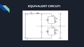
SINGLE PHASE
INDUCTION MOTOR
PRESENTATION ON
INTRODUCTION
Construction of Single Phase Induction Motor
●
STATOR:As its name indicates stator is a stationary part of induction motor. A single
phase AC supply is given to the stator of single phase induction motor.
● ROTOR: The rotor is a rotating part of an induction motor. The rotor connects the
mechanical load through the shaft. The rotor in the single-phase induction motor is of
squirrel cage rotor type.
WORKING PRINCIPLE
We know that for the working of any electrical motor whether its AC or DC motor,
we require two fluxes as the interaction of these two fluxes produced the required
torque.
When we apply a single phase AC supply to the stator winding of single phase induction
motor, the alternating current starts flowing through the stator or main winding. This
alternating current produces an alternating flux called main flux. This main flux also links
with the rotor conductors and hence cut the rotor conductors. According to the Faraday’s
law of electromagnetic induction, emf gets induced in the rotor. As the rotor circuit is
closed one so, the current starts flowing in the rotor. This current is called the rotor
current. This rotor current produces its flux called rotor flux. Since this flux is produced due
to the induction principle so, the motor working on this principle got its name as an
induction motor. Now there are two fluxes one is main flux, and another is called rotor flux.
These two fluxes produce the desired torque which is required by the motor to rotate.
Torque Slip Characteristics
DOUBLE FIELD REVOLVING THEORY:
According to this theory, any alternating quantity can be resolved into two rotating components which rotate in opposite
directions and each having magnitude as half of the maximum magnitude of the alternating quantity.According to double
revolving field theory, consider the two components of the stator flux, each having magnitude half of maximum magnitude of stator flux
i.e. (Φ1m/2). Both these components are rotating in opposite directions at the synchronous speed Ns which is dependent on frequency
and stator poles.
Let Φf is forward component rotating in anticlockwise direction while Φb is the backward component rotating in clockwise direction. So
resultant of these two is the original stator flux.
Now at starting condition, both the forward and backward components of flux are exactly opposite to each other. Also, both of
these components of flux are equal in magnitude. So, they cancel each other and hence the net torque experienced by the rotor at
the starting condition is zero. So, the single phase induction motors are not self-starting motors.
EQUIVALENT CIRCUIT:
MEASUREMENT OF
EQUIVALENT CIRCUIT
PARAMETERS
NO LOAD TEST:
This test is similar to the open circuit test on
transformer.The test is performed at poly-phase
voltages and rated frequency applied to the stator
terminals.
No Load Test is an indirect method used for
determining the efficiency and also to determine
the circuit parameters of the equivalent circuit of
the three-phase induction motors.
BLOCKED ROTOR TEST:
A blocked rotor test is conducted on an induction motor. It is
also known as short circuit test, locked rotor test or stalled
torque test.[1] From this test, short circuit current at normal
voltage, power factor on short circuit, total leakage reactance,
and starting torque of the motor can be found.[2][3] The test is
conducted at low voltage because if the applied voltage was
normal voltage then the current through the stator windings
would be high enough to overheat the windings and damage
them.[4] The blocked rotor torque test is not performed on
wound-rotor motors because the starting torque can be varied
as desired. However, a blocked rotor current test is conducted
on squirrel cage rotor motors.
THANK YOU

SINGLE PHASE INDUCTION MOTOR

  • 1.
  • 2.
    INTRODUCTION Construction of SinglePhase Induction Motor ● STATOR:As its name indicates stator is a stationary part of induction motor. A single phase AC supply is given to the stator of single phase induction motor. ● ROTOR: The rotor is a rotating part of an induction motor. The rotor connects the mechanical load through the shaft. The rotor in the single-phase induction motor is of squirrel cage rotor type.
  • 3.
    WORKING PRINCIPLE We knowthat for the working of any electrical motor whether its AC or DC motor, we require two fluxes as the interaction of these two fluxes produced the required torque. When we apply a single phase AC supply to the stator winding of single phase induction motor, the alternating current starts flowing through the stator or main winding. This alternating current produces an alternating flux called main flux. This main flux also links with the rotor conductors and hence cut the rotor conductors. According to the Faraday’s law of electromagnetic induction, emf gets induced in the rotor. As the rotor circuit is closed one so, the current starts flowing in the rotor. This current is called the rotor current. This rotor current produces its flux called rotor flux. Since this flux is produced due to the induction principle so, the motor working on this principle got its name as an induction motor. Now there are two fluxes one is main flux, and another is called rotor flux. These two fluxes produce the desired torque which is required by the motor to rotate.
  • 4.
  • 5.
    DOUBLE FIELD REVOLVINGTHEORY: According to this theory, any alternating quantity can be resolved into two rotating components which rotate in opposite directions and each having magnitude as half of the maximum magnitude of the alternating quantity.According to double revolving field theory, consider the two components of the stator flux, each having magnitude half of maximum magnitude of stator flux i.e. (Φ1m/2). Both these components are rotating in opposite directions at the synchronous speed Ns which is dependent on frequency and stator poles. Let Φf is forward component rotating in anticlockwise direction while Φb is the backward component rotating in clockwise direction. So resultant of these two is the original stator flux. Now at starting condition, both the forward and backward components of flux are exactly opposite to each other. Also, both of these components of flux are equal in magnitude. So, they cancel each other and hence the net torque experienced by the rotor at the starting condition is zero. So, the single phase induction motors are not self-starting motors.
  • 6.
  • 7.
  • 8.
    NO LOAD TEST: Thistest is similar to the open circuit test on transformer.The test is performed at poly-phase voltages and rated frequency applied to the stator terminals. No Load Test is an indirect method used for determining the efficiency and also to determine the circuit parameters of the equivalent circuit of the three-phase induction motors.
  • 9.
    BLOCKED ROTOR TEST: Ablocked rotor test is conducted on an induction motor. It is also known as short circuit test, locked rotor test or stalled torque test.[1] From this test, short circuit current at normal voltage, power factor on short circuit, total leakage reactance, and starting torque of the motor can be found.[2][3] The test is conducted at low voltage because if the applied voltage was normal voltage then the current through the stator windings would be high enough to overheat the windings and damage them.[4] The blocked rotor torque test is not performed on wound-rotor motors because the starting torque can be varied as desired. However, a blocked rotor current test is conducted on squirrel cage rotor motors.
  • 10.