UNIT:3
Drilling and MillingMachines
Drilling operations- Twist drill geometry Radial drilling machine-Jigs and
Fixtures,
Definition-Need of Jigs and Fixtures Drill Jig-Locating devices.
Milling-Classification,
Column and knee type milling machine - Milling cutters and classification-
Fundamentals of
milling processes-Milling operations. Indexing methods-Simple and
compounding. Cutting
speed, feed, depth of cut and machining time
2.
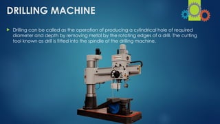
DRILLING MACHINE
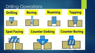
Drillingcan be called as the operation of producing a cylindrical hole of required
diameter and depth by removing metal by the rotating edges of a drill. The cutting
tool known as drill is fitted into the spindle of the drilling machine.
3.
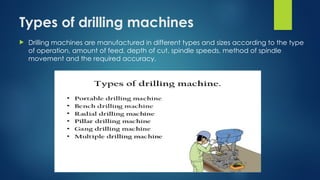
Types of drillingmachines
Drilling machines are manufactured in different types and sizes according to the type
of operation, amount of feed, depth of cut, spindle speeds, method of spindle
movement and the required accuracy.
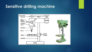
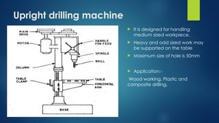
Upright drilling machine
It is designed for handling
medium sized workpiece.
Heavy and odd sized work may
be supported on the table
Maximum size of hole is 50mm
Application:-
Wood working, Plastic and
composite drilling.
7.
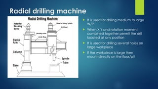
Radial drilling machine
It is used for drilling medium to large
W/P
When X,Y and rotation moment
combined together permit the drill
located at any position
It is used for drilling several holes on
large workpiece
If the workpiece is large then
mount directly on the floor/pit
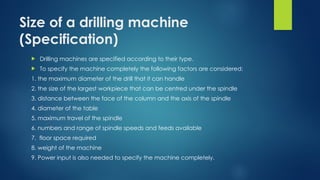
Size of adrilling machine
(Specification)
Drilling machines are specified according to their type.
To specify the machine completely the following factors are considered:
1. the maximum diameter of the drill that it can handle
2. the size of the largest workpiece that can be centred under the spindle
3. distance between the face of the column and the axis of the spindle
4. diameter of the table
5. maximum travel of the spindle
6. numbers and range of spindle speeds and feeds available
7. floor space required
8. weight of the machine
9. Power input is also needed to specify the machine completely.
12.
Work Holding Devices
The devices used for holding the work in a drilling machine are
1. Drill vise
2. ‘T’ - bolts and clamps
3 V - block
4 Angle plate
5. Drill jigs
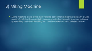
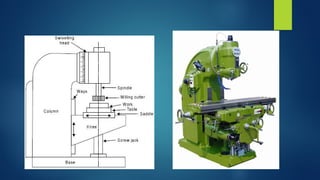
B) Milling Machine
Milling machine is one of the most versatile conventional machine tools with a wide
range of metal cutting capability. Many complicated operations such as indexing,
gang milling, and straddle milling etc. can be carried out on a milling machine
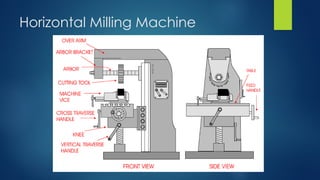
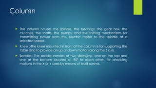
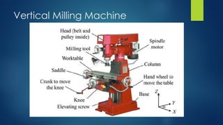
Column
The columnhouses the spindle, the bearings, the gear box, the
clutches, the shafts, the pumps, and the shifting mechanisms for
transmitting power from the electric motor to the spindle at a
selected speed.
Knee :-The knee mounted in front of the column is for supporting the
table and to provide an up or down motion along the Z axis.
Saddle:- The saddle consists of two slideways, one on the top and
one at the bottom located at 90º to each other, for providing
motions in the X or Y axes by means of lead screws.
17.
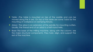
Table :-Thetable is mounted on top of the saddle and can be
moved along the X axis. On top of the table are some T-slots for the
mounting of workpiece or clamping fixtures.
Arbor:- The arbor is an extension of the spindle for mounting cutters.
Usually, the thread end of an arbor is of left-hand helix.
Base:-The base of the milling machine, along with the column, are
the major structural components. They hold, align, and support the
rest of the machine.
18.
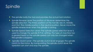
Spindle
The spindleholds the tool and provides the actual tool rotation.
Spindle Reverse Lever The position of this lever determines the
spindle direction. The three positions of the handle are; In, Middle,
and Out. The middle position is the neutral position. Never move the
spindle reverse lever when the spindle is turning.
Spindle Speed Selection Lever:-The spindle speed selection lever is
used to change the spindle R.P.M. setting. This type of machine has
a geared head so the spindle speed can only be changed when
the spindle is stopped.
Spindle Clutch Lever :-The spindle clutch lever engages the spindle
clutch to the motor. By manipulating the spindle clutch lever the
operator can start and stop the spindle.
19.
Feed Rate SelectionLever
The feed rate selection lever is used to change the feed rate
setting. The feed rate settings are expressed in inches per minute.
Motor Start and Stop Buttons
The motor start and stop buttons control the power to the main
motor for the machine
21.
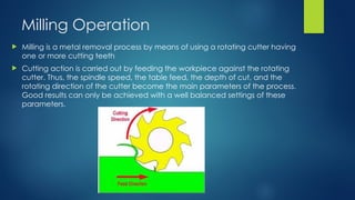
Milling Operation
Millingis a metal removal process by means of using a rotating cutter having
one or more cutting teeth
Cutting action is carried out by feeding the workpiece against the rotating
cutter. Thus, the spindle speed, the table feed, the depth of cut, and the
rotating direction of the cutter become the main parameters of the process.
Good results can only be achieved with a well balanced settings of these
parameters.
22.
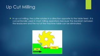
Up Cut Milling
In up cut milling, the cutter rotates in a direction opposite to the table feed . It is
conventionally used in most milling operations because the backlash between
the leadscrew and the nut of the machine table can be eliminated.
23.
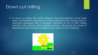
Down cut milling
In down cut milling, the cutter rotates in the same direction as the table
feed . This method is also known as Climb Milling and can only be used on
machines equipped with a backlash eliminator or on a CNC milling
machine. This method, when properly treated, will require less power in
feeding the table and give a better surface finish on the workpiece
24.
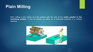
Plain Milling
Plain millingis the milling of a flat surface with the axis of the cutter parallel to the
machining surface. It can be carried out either on a horizontal machine or a vertical
machine
25.
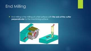
End Milling
EndMilling is the milling of a flat surface with the axis of the cutter
perpendicular to the machining surface
26.
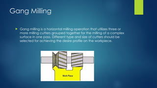
Gang Milling
Gangmilling is a horizontal milling operation that utilizes three or
more milling cutters grouped together for the milling of a complex
surface in one pass. Different type and size of cutters should be
selected for achieving the desire profile on the workpiece.
27.
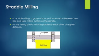
Straddle Milling
Instraddle milling, a group of spacers is mounted in between two
side and face milling cutters on the spindle.
For the milling of two surfaces parallel to each other at a given
distance.
28.
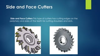
Side and FaceCutters
Side and Face Cutters This type of cutters has cutting edges on the
periphery and sides of the teeth for cutting shoulders and slots.
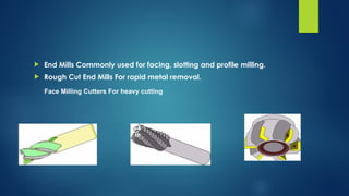
End MillsCommonly used for facing, slotting and profile milling.
Rough Cut End Mills For rapid metal removal.
Face Milling Cutters For heavy cutting
The machinemay be of the plain or universal type and has all the
movements of the table for a proper setting and feeding the work.
The spindle head is clamped to the vertical column which is
swivelled at an angle. It allowing the milling cutter fixed on the
spindle to work on angular surfaces. In some machines, the spindle
can also be adjusted up or down relative to the work.
36.
It ismost commonly used milling machine used for general shop
work
The table is mounted on the knee which in turn is mounted on the
vertical slides of the main column
The knee is vertically adjustable on the column so that the table can
be moved up and down to the accommodate work of various
height.
37.
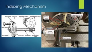
Indexing
It isa machining process carried out for cutting teeth of different
shapes by using milling cutters or involute cutters
“ the process of evenly dividing the circumference of a circular
workpiece into equally spaced divisions, in order to perform certain
machining operations such as gear teeth cutting, splines, grooves in
reamers & taps
In otherwords, 40 revolution of crank will make the worm
wheel/workpiece to complete one full turn or 360° revolution
thereby making the ratio 40:1
Therefore, one turn of the index crank =360/40=9°
For 2 division on work piece, the crank has to rotate = 40/2 = 20 turns
for each divisions
For 10 division on work piece, the crank has to rotate = 40/10 = 4
turns for each divisions
Therefore for N divisions on the work piece, the crank has to be
rotated 40/N for each division.
To index 23divisions on workpiece
Index crank movement=40/N=40/23= ,for reach division
1 COMPLETE REVOLUTION OF CRANK. SELECT 17TH
NUMBER HOLE ON 23
CIRCLES