Download to read offline


![lion of the cutter. However, there are factor
that limit. or prevent the use of multiple starts
hob for all ca e .
The Hob
As more and more threads are designed into
the tool, the lead of the thread will increase.
Normally. a thread lead angle of 2-60
will be
acceptable. Beyondix degrees, the :Ieft and
right side of the cutting tooth will be loaded
unequally, which will cause poor tool life. To
compensate fo£, !:his pmb.lem, ,!he diameter of
'the [001 can be increa ed slightly. but. with a
reduction in RPM to maintain the arne SFM.
Alternanvely, the gash of the hob can be made
helical to position the cutting tooth perpendicu-
lar to the cutting action.
To calculate the thread angle of a hob. 1.1 e
the following formula:
Tan a = Thread in Hob
DP x Hob Diameter
Example:
Tan a=_]_
20x.2
Tan ,a = .025
a= 1° 2S' 56"
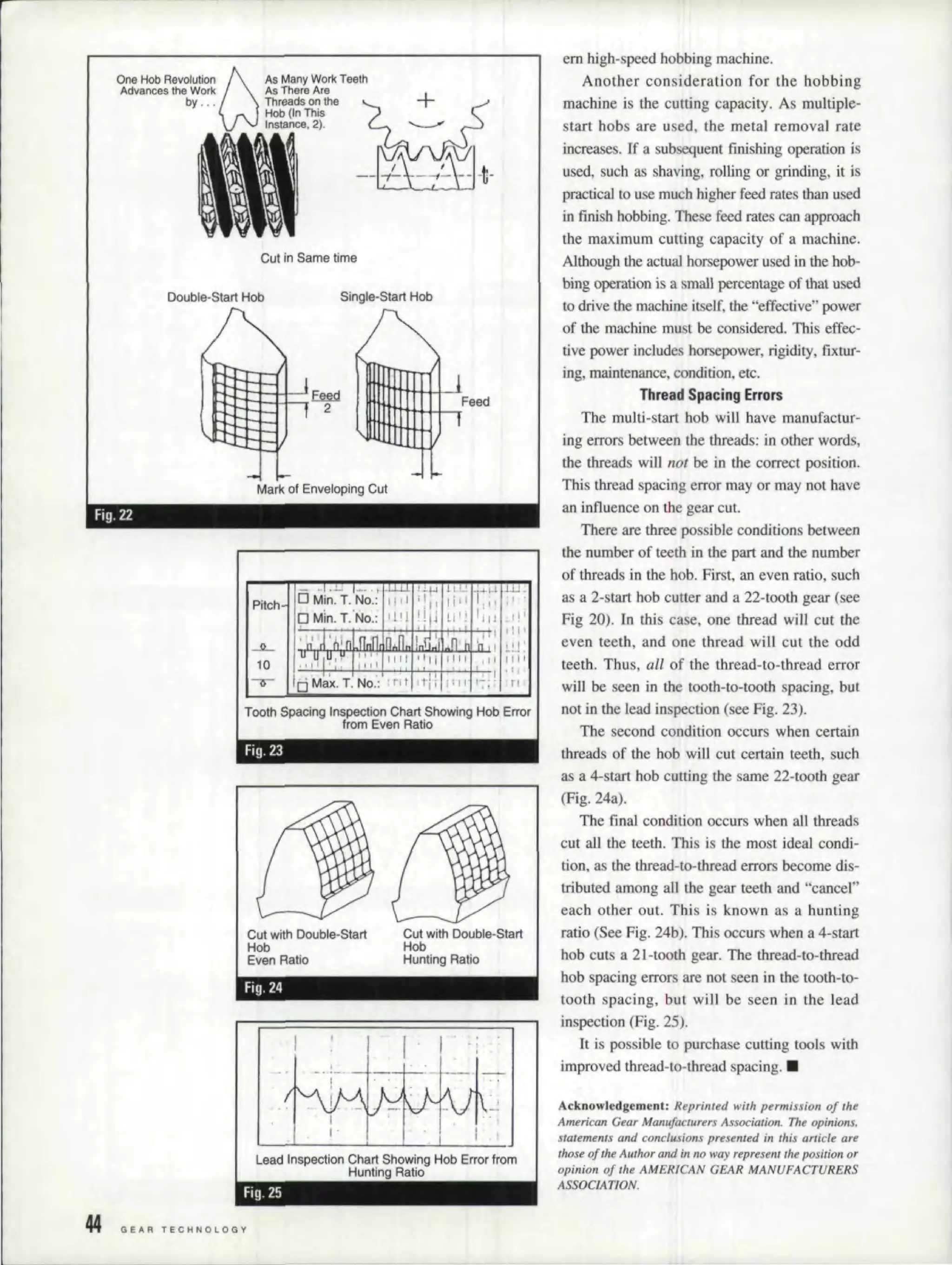
Another problem with multiple thread hobs
is the number of effective gashe generating
lbe profile, Again. all factor being equal. a
two-start hob with twelve gashe will generate
the gear profile with six of the gashes ver usa
single-start hob with twelve gashe .
The Ho'bbing Macbine,
As the number of threads in the tool
increa e , the work will index. faster. This
means that. the work pindle of the bobbing
machine must be able to rotate at higher
speed . On workpieces with high numbers of
teeth. the machine peed is not aproblem, but
for gears with a low number of teeth. the hob-
bing machine mu t be designed correctly.
Several machine design solutions are used.
For traditional worms and worm wheel work
spmdle drives. a multiple- uart worm and
worm wheel can be u ed. Four, eight and more
thread worms are common. Another approach
is to utilize a helical gear index system. Both
sy terns work effectively in providing a mod-
Fig. 118
fig. 19
Height of
Feed Mar1<s
1i
Feed Marks froml Hobbing
---
Fig. 21
JANUARYJFEIIRU"RY laa. 43:](https://image.slidesharecdn.com/hobbing-211125104845/75/Hobbing-6-2048.jpg)

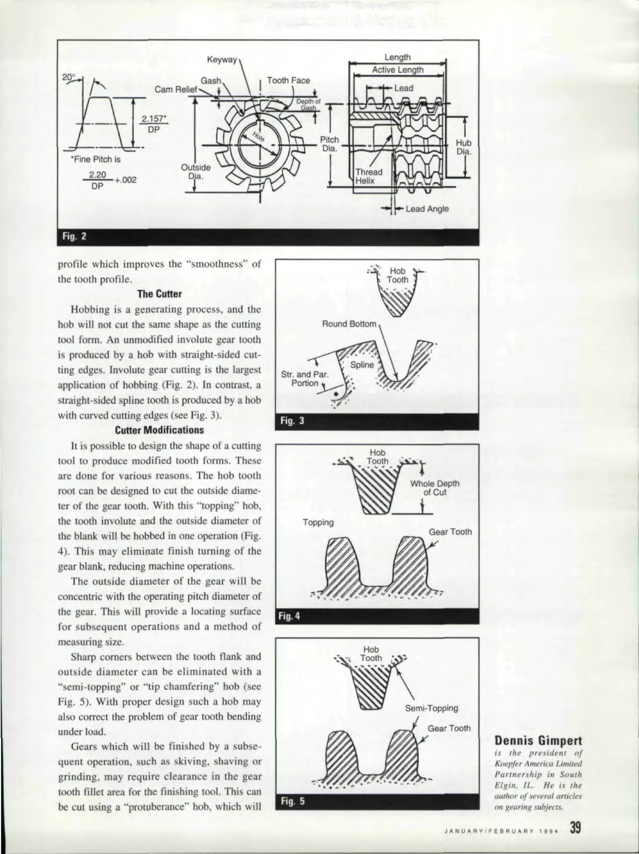
The gear hobbing process involves using a hob (a cylindrical cutting tool with teeth) to cut gear teeth onto a workpiece. As the hob and workpiece rotate, the hob is fed axially across the face of the workpiece to gradually form each tooth. Modifications can be made to the hob shape to produce specialized tooth forms. Multiple-start hobs can increase production speed by indexing the workpiece multiple teeth with each hob revolution, but they introduce challenges like uneven thread spacing that can affect gear quality. Proper machine design and process parameters are needed to optimize gear hobbing.