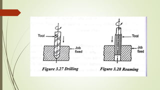
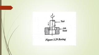
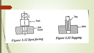
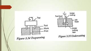
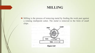
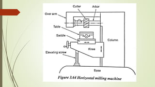
UNIT 3
Shaper - Types of operations. Drilling, reaming,
boring, Tapping. Milling operations-types of milling
cutter. Gear cutting – forming and generation principle
and construction of gear milling, hobbing and gear
shaping processes –finishing of gears.
SHAPER
 Shaper, planner and slotter are used for machining flat surface which
may be horizontal, vertical or inclined surfaces. Single point cutting
tools are mainly used in these machines.
 Drilling, grinding, boring, milling and broaching machines are not used
for machining flat surfaces but they are performing specific operations
by using a multi point cutting tool
PRINCIPLE OF OPERATION
 The shaper having a reciprocating type of machine tool with single
point cutting tool is used to produce flat surfaces.
 It has the three important parts such as
Table
Tool head
Ram
MACHINING THE VARIOUS TYPE OF
FLAT SURFACES
 The table is moved cross wise direction to machine the horizontal
surfaces.
 The tool head is moved perpendicular to the table in downward
direction to machine the vertical surfaces.
 The tool head is fed at an angle to produce inclined surfaces.
CLASSIFICATION OF SHAPER
 According to the type of driving mechanism
 Crank drive type
 Whit worth driving mechanism
 Hydraulic drive type
 According to the position of ram
 Horizontal shaper
 Vertical shaper
 Travelling head shaper
 According to the table design
 Plain shaper
 Universal shaper
 According to the type of cutting stroke
 Push out type
 Draw cut type
PRINCIPLE PARTS OF A SHAPER
 The different parts of a shaper are listed
Base
Column
Cross rail
Saddle
Table
Ram
Tool head
TOOL HEAD
SHAPER SPECIFICATION
 Maximum length of stroke
 Maximum crosswise movement of the table
 Maximum vertical adjustment of the table
 Type of driving mechanism
 Power of the motor
 Available speed and feed
 Type of shaper-plain or universal
 Floor space required
 Total weight of the shaper
 Ratio of cutting stroke time and return stroke time
TYPE OF QUICK RETURN MECHANISM
 The following are three types of quick return mechanism
Hydraulic drive
Crank and slotted link mechanism
Whit worth quick return mechanism
Hydraulic drive
Crank and slotted link mechanism
Quick return principle
Whit worth quick return mechanism
SHAPER OPERATIONS
 Machining horizontal surface
 Machining vertical surface
 Machining angular surface
 Machining slots, grooves and keyways
 Machining irregular surfaces
Machining horizontal surface
Machining vertical surface
Machining angular surface
Machining slots, grooves and keyways
Machining irregular surfaces
DRILLING
 Drilling is the process of producing hole on the work piece by using a
rotating cutter called drill. The machine on which the drilling is carried
out is called drilling machine.
 Drilling machine can also used for boring, counter boring, counter
sinking, reaming, tapping and spot facing operations.
CLASSIFICATION OF DRILLING MACHINE
 Portable drilling machine
 Sensitive drilling machine
 Bench type
 Floor type
 Upright drilling machine
 Round column type or pillar type
 Box column type or square section type
 Radial drilling machine
 Plain type
 Semi-universal type
 Universal type
 Gang drilling machine
 Multiple spindle drilling machine
 Automatic drilling machine
 Deep hole drilling machine
PORTABLE DRILLING MACHINE
SENSITIVE DRILLING MACHINE
UPRIGHT DRILLING MACHINE
RADIAL DRILLING MACHINE
PLAIN TYPE
The following adjustments are available in this type
 Vertical movement of the radial arm with respect to the column
 Circular movement of the radial arm about the column
 Horizontal movement of the tool along the arm ways
SEMI UNIVERSAL TYPE
 In addition to the above three movements as in the case of plain
type, the fourth movement of the tool post can be swung about a
horizontal axis perpendicular to the arm. This arrangement permits
for drilling a hole inclined at any angle to the horizontal plane
UNIVERSAL TYPE
 In addition to the above fourth movement as in the case of semi
universal type, the fifth movement of the radial arm is rotated on a
horizontal axis.
 All these movements enable the universal drilling machine to drill on a
job at any angle in either horizontal plane or vertical plane or in both
the planes.
MULTIPLE SPINDLE DRILLING MACHINE
 This machine is more suitable for mass production. In this machine,
several holes of different sizes can simultaneously be drilled. It has
several spindles. They are driven by a single motor by using set of
gears .
 All spindles holding the drills are fed into the work at the same time.
The feed is given either by raising the table or lowering the spindle
head.
GANG DRILLING MACHINE
 When a number of single spindles with essential speed and feed are
mounted side by side on one base and have a common worktable
known as gang drilling machine
AUTOMATIC DRILLING MACHINE
 A series of drilling machines are arranged to perform more than one
operation at a time in sequence of successive work stations is called
automatic drilling machine.
DEEP HOLE DRILLING MACHINE
 Deep hole drilling machines are used when the drill hole depth exceeds
the normal drill hole depth.
SPECIFICATION OF DRILLING
MACHINE
 Maximum size of the drill in mm that the machine can be operated
 Table size of maximum dimensions of a job can mount on a table in
square metre.
 Maximum spindle travel in mm
 The number of spindle speed and range of spindle speeds are in rpm
 Power input of the machine is in HP
 Floor space required
 Net weight of the machine
DRILLING OPERATIONS
 Drilling
 Reaming
 Boring
 Counter boring
 Counter sinking
 Spot facing
 Tapping
 Trepanning
 Undercutting
 Grinding
 Lapping
 honing
MOUNTING THE DRILL TOOL
 Both taper shank and straight shank drills can be mounted on the
drilling machine spindle in a number of ways.
Fitting directly in the spindle
By using a sleeve
By using a socket
By means of chucks
BORING
 Boring is the process of enlarging and locating previously drilled holes
with a single point cutting tool.
TYPE OF BORING MACHINE
 Horizontal boring machine
Table type
Floor type
Planer type
Multiple head type
 Vertical boring machine
 Precision boring machine
 Jig boring machine
Horizontal boring machine
Floor type
Planer type
Multiple head type
Vertical boring machine
OPERATIONS IN HORIZONTAL
BORING MACHINE
 Boring
 Face milling
 Drilling
 Reaming
OPERATIONS IN VERTICAL BORING
MACHINE
 Cylindrical turning
 Taper turning
 Boring
 Turning plain surface
 Necking
JIG BORING MACHINE
 A jig boring machine is a precision boring machine used for boring
accurate holes at centre to centre distances.
 There are mainly two types of jig boring machines
Single vertical column type
Planer type
MILLING
 Milling is the process of removing metal by feeding the work past against
a rotating multipoint cutter. The metal is removed in the form of small
chips.
SPECIFICATION OF MILLING
MACHINE
 The table length and width
 Maximum longitudinal cross and vertical travel of the table
 Number of spindle speeds and feeds
 Power of driving motor
 Floor space required
 Type of milling machine
CLASSIFICATION OF MILLING
MACHINE
 Column and knee types
 Plain milling machine
 vertical milling machine
 Universal milling machine
 Ram type milling machine
 omniversal milling machine
 Bed type milling machine
 Simplex milling machine
 Duplex milling machine
 Triplex milling machine
 Plano-type milling machine
 Special purpose milling machine
 Rotary table milling machine
 Drum milling machine
 Profile milling machine
WORK HOLDING DEVICES
 The following work holding devices are used for clamping the work in
the milling machine.
 Swivel vice
 Universal vice
 Indexing head
TOOL HOLDING DEVICES
 The following tool holding devices are used in milling machines.
Arbors
Adaptors
Collets
MILLING CUTTERS
Classification of cutters
According to the shape of the tooth
Milled tooth cutters
Form relieved cutters
According to the type of operation
Plain milling cutter
Side milling cutters
End milling cutters
Angle milling cutters
T slot milling cutter
Slitting saws
Form milling cutter
Fly cutters
MILLING OPERATIONS
 Plain or slab milling
 Face milling
 Angular milling
 Straddle milling
 Gang milling
 Form milling
 End milling
 T slot milling
 Gear cutting
DIVIDING HEADS
These are the following types of dividing heads
Plain or simple dividing head
Universal dividing head
Optical dividing head
INDEXING METHODS
 Direct or rapid indexing
 Plain or simple indexing
 Differential indexing
 Compound indexing
 Angular indexing
GEAR CUTTING
 Gear cutting by single point form tool
 Gear cutting by shear speed shaping process
 Gear milling using a formed end mill
 Gear broaching
 Template method
Gear cutting by single point form tool
Gear cutting by shear speed shaping process
Gear milling using a formed end mill
Gear broaching
Template method
GEAR GENERATION PRINCIPLE AND
CONSTRUCTION OF GEAR MILLING
 The common gear generation processes are given below
 Gear shaping process
 Gear planning process
 Gear hobbing process
GEAR SHAPING PROCESS
APPLICATIONS
 Gear shaping is used for generating both internal and external spur
gears.
 Helical gears can also be generated using special attachments.
GEAR PLANNING PROCESS
GEAR HOBBING PROCESS
FINISHING OF GEARS
 Generally the gear teeth are produced by any one of the generating
processes, but the gear does not be more accurate with good quality
surface.
 The rough surface gear teeth occur due to vibrations causing noise,
excessive wear, play and backlash between meshing pair of gears.
 Therefore, the gear finishing is carried at last in gear manufacturing.
GEAR SHAVING
ROLL FINISHING OF GEAR TOOTH
GEAR BURNISHING
GEAR LAPPING
GEAR HONING

MANUFACTURING PROCESS-II UNIT-3 SHAPER MACHINES

  • 1.
    UNIT 3 Shaper -Types of operations. Drilling, reaming, boring, Tapping. Milling operations-types of milling cutter. Gear cutting – forming and generation principle and construction of gear milling, hobbing and gear shaping processes –finishing of gears.
  • 2.
    SHAPER  Shaper, plannerand slotter are used for machining flat surface which may be horizontal, vertical or inclined surfaces. Single point cutting tools are mainly used in these machines.  Drilling, grinding, boring, milling and broaching machines are not used for machining flat surfaces but they are performing specific operations by using a multi point cutting tool
  • 3.
    PRINCIPLE OF OPERATION The shaper having a reciprocating type of machine tool with single point cutting tool is used to produce flat surfaces.  It has the three important parts such as Table Tool head Ram
  • 4.
    MACHINING THE VARIOUSTYPE OF FLAT SURFACES  The table is moved cross wise direction to machine the horizontal surfaces.  The tool head is moved perpendicular to the table in downward direction to machine the vertical surfaces.  The tool head is fed at an angle to produce inclined surfaces.
  • 5.
    CLASSIFICATION OF SHAPER According to the type of driving mechanism  Crank drive type  Whit worth driving mechanism  Hydraulic drive type  According to the position of ram  Horizontal shaper  Vertical shaper  Travelling head shaper  According to the table design  Plain shaper  Universal shaper  According to the type of cutting stroke  Push out type  Draw cut type
  • 6.
    PRINCIPLE PARTS OFA SHAPER  The different parts of a shaper are listed Base Column Cross rail Saddle Table Ram Tool head
  • 8.
  • 9.
    SHAPER SPECIFICATION  Maximumlength of stroke  Maximum crosswise movement of the table  Maximum vertical adjustment of the table  Type of driving mechanism  Power of the motor  Available speed and feed  Type of shaper-plain or universal  Floor space required  Total weight of the shaper  Ratio of cutting stroke time and return stroke time
  • 10.
    TYPE OF QUICKRETURN MECHANISM  The following are three types of quick return mechanism Hydraulic drive Crank and slotted link mechanism Whit worth quick return mechanism
  • 11.
  • 12.
    Crank and slottedlink mechanism
  • 13.
  • 14.
    Whit worth quickreturn mechanism
  • 15.
    SHAPER OPERATIONS  Machininghorizontal surface  Machining vertical surface  Machining angular surface  Machining slots, grooves and keyways  Machining irregular surfaces
  • 16.
  • 17.
  • 18.
  • 19.
  • 20.
  • 21.
    DRILLING  Drilling isthe process of producing hole on the work piece by using a rotating cutter called drill. The machine on which the drilling is carried out is called drilling machine.  Drilling machine can also used for boring, counter boring, counter sinking, reaming, tapping and spot facing operations.
  • 22.
    CLASSIFICATION OF DRILLINGMACHINE  Portable drilling machine  Sensitive drilling machine  Bench type  Floor type  Upright drilling machine  Round column type or pillar type  Box column type or square section type  Radial drilling machine  Plain type  Semi-universal type  Universal type  Gang drilling machine  Multiple spindle drilling machine  Automatic drilling machine  Deep hole drilling machine
  • 23.
  • 24.
  • 25.
  • 26.
  • 27.
    PLAIN TYPE The followingadjustments are available in this type  Vertical movement of the radial arm with respect to the column  Circular movement of the radial arm about the column  Horizontal movement of the tool along the arm ways
  • 28.
    SEMI UNIVERSAL TYPE In addition to the above three movements as in the case of plain type, the fourth movement of the tool post can be swung about a horizontal axis perpendicular to the arm. This arrangement permits for drilling a hole inclined at any angle to the horizontal plane
  • 29.
    UNIVERSAL TYPE  Inaddition to the above fourth movement as in the case of semi universal type, the fifth movement of the radial arm is rotated on a horizontal axis.  All these movements enable the universal drilling machine to drill on a job at any angle in either horizontal plane or vertical plane or in both the planes.
  • 30.
    MULTIPLE SPINDLE DRILLINGMACHINE  This machine is more suitable for mass production. In this machine, several holes of different sizes can simultaneously be drilled. It has several spindles. They are driven by a single motor by using set of gears .  All spindles holding the drills are fed into the work at the same time. The feed is given either by raising the table or lowering the spindle head.
  • 31.
    GANG DRILLING MACHINE When a number of single spindles with essential speed and feed are mounted side by side on one base and have a common worktable known as gang drilling machine
  • 32.
    AUTOMATIC DRILLING MACHINE A series of drilling machines are arranged to perform more than one operation at a time in sequence of successive work stations is called automatic drilling machine.
  • 33.
    DEEP HOLE DRILLINGMACHINE  Deep hole drilling machines are used when the drill hole depth exceeds the normal drill hole depth.
  • 34.
    SPECIFICATION OF DRILLING MACHINE Maximum size of the drill in mm that the machine can be operated  Table size of maximum dimensions of a job can mount on a table in square metre.  Maximum spindle travel in mm  The number of spindle speed and range of spindle speeds are in rpm  Power input of the machine is in HP  Floor space required  Net weight of the machine
  • 35.
    DRILLING OPERATIONS  Drilling Reaming  Boring  Counter boring  Counter sinking  Spot facing  Tapping  Trepanning  Undercutting  Grinding  Lapping  honing
  • 41.
    MOUNTING THE DRILLTOOL  Both taper shank and straight shank drills can be mounted on the drilling machine spindle in a number of ways. Fitting directly in the spindle By using a sleeve By using a socket By means of chucks
  • 44.
    BORING  Boring isthe process of enlarging and locating previously drilled holes with a single point cutting tool.
  • 45.
    TYPE OF BORINGMACHINE  Horizontal boring machine Table type Floor type Planer type Multiple head type  Vertical boring machine  Precision boring machine  Jig boring machine
  • 46.
  • 47.
  • 48.
  • 49.
  • 50.
  • 52.
    OPERATIONS IN HORIZONTAL BORINGMACHINE  Boring  Face milling  Drilling  Reaming
  • 53.
    OPERATIONS IN VERTICALBORING MACHINE  Cylindrical turning  Taper turning  Boring  Turning plain surface  Necking
  • 54.
    JIG BORING MACHINE A jig boring machine is a precision boring machine used for boring accurate holes at centre to centre distances.  There are mainly two types of jig boring machines Single vertical column type Planer type
  • 56.
    MILLING  Milling isthe process of removing metal by feeding the work past against a rotating multipoint cutter. The metal is removed in the form of small chips.
  • 57.
    SPECIFICATION OF MILLING MACHINE The table length and width  Maximum longitudinal cross and vertical travel of the table  Number of spindle speeds and feeds  Power of driving motor  Floor space required  Type of milling machine
  • 58.
    CLASSIFICATION OF MILLING MACHINE Column and knee types  Plain milling machine  vertical milling machine  Universal milling machine  Ram type milling machine  omniversal milling machine  Bed type milling machine  Simplex milling machine  Duplex milling machine  Triplex milling machine  Plano-type milling machine  Special purpose milling machine  Rotary table milling machine  Drum milling machine  Profile milling machine
  • 68.
    WORK HOLDING DEVICES The following work holding devices are used for clamping the work in the milling machine.  Swivel vice  Universal vice  Indexing head
  • 72.
    TOOL HOLDING DEVICES The following tool holding devices are used in milling machines. Arbors Adaptors Collets
  • 76.
    MILLING CUTTERS Classification ofcutters According to the shape of the tooth Milled tooth cutters Form relieved cutters
  • 77.
    According to thetype of operation Plain milling cutter Side milling cutters End milling cutters Angle milling cutters T slot milling cutter Slitting saws Form milling cutter Fly cutters
  • 88.
    MILLING OPERATIONS  Plainor slab milling  Face milling  Angular milling  Straddle milling  Gang milling  Form milling  End milling  T slot milling  Gear cutting
  • 98.
    DIVIDING HEADS These arethe following types of dividing heads Plain or simple dividing head Universal dividing head Optical dividing head
  • 102.
    INDEXING METHODS  Director rapid indexing  Plain or simple indexing  Differential indexing  Compound indexing  Angular indexing
  • 103.
    GEAR CUTTING  Gearcutting by single point form tool  Gear cutting by shear speed shaping process  Gear milling using a formed end mill  Gear broaching  Template method
  • 104.
    Gear cutting bysingle point form tool
  • 105.
    Gear cutting byshear speed shaping process
  • 106.
    Gear milling usinga formed end mill
  • 107.
  • 108.
  • 109.
    GEAR GENERATION PRINCIPLEAND CONSTRUCTION OF GEAR MILLING  The common gear generation processes are given below  Gear shaping process  Gear planning process  Gear hobbing process
  • 110.
  • 112.
    APPLICATIONS  Gear shapingis used for generating both internal and external spur gears.  Helical gears can also be generated using special attachments.
  • 113.
  • 114.
  • 116.
    FINISHING OF GEARS Generally the gear teeth are produced by any one of the generating processes, but the gear does not be more accurate with good quality surface.  The rough surface gear teeth occur due to vibrations causing noise, excessive wear, play and backlash between meshing pair of gears.  Therefore, the gear finishing is carried at last in gear manufacturing.
  • 117.
  • 118.
  • 119.
  • 120.
  • 121.