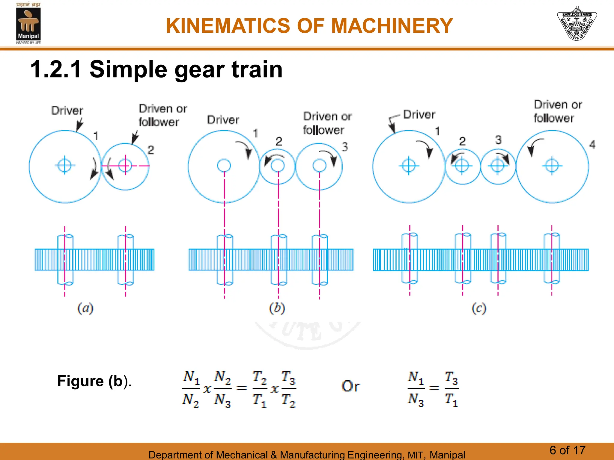
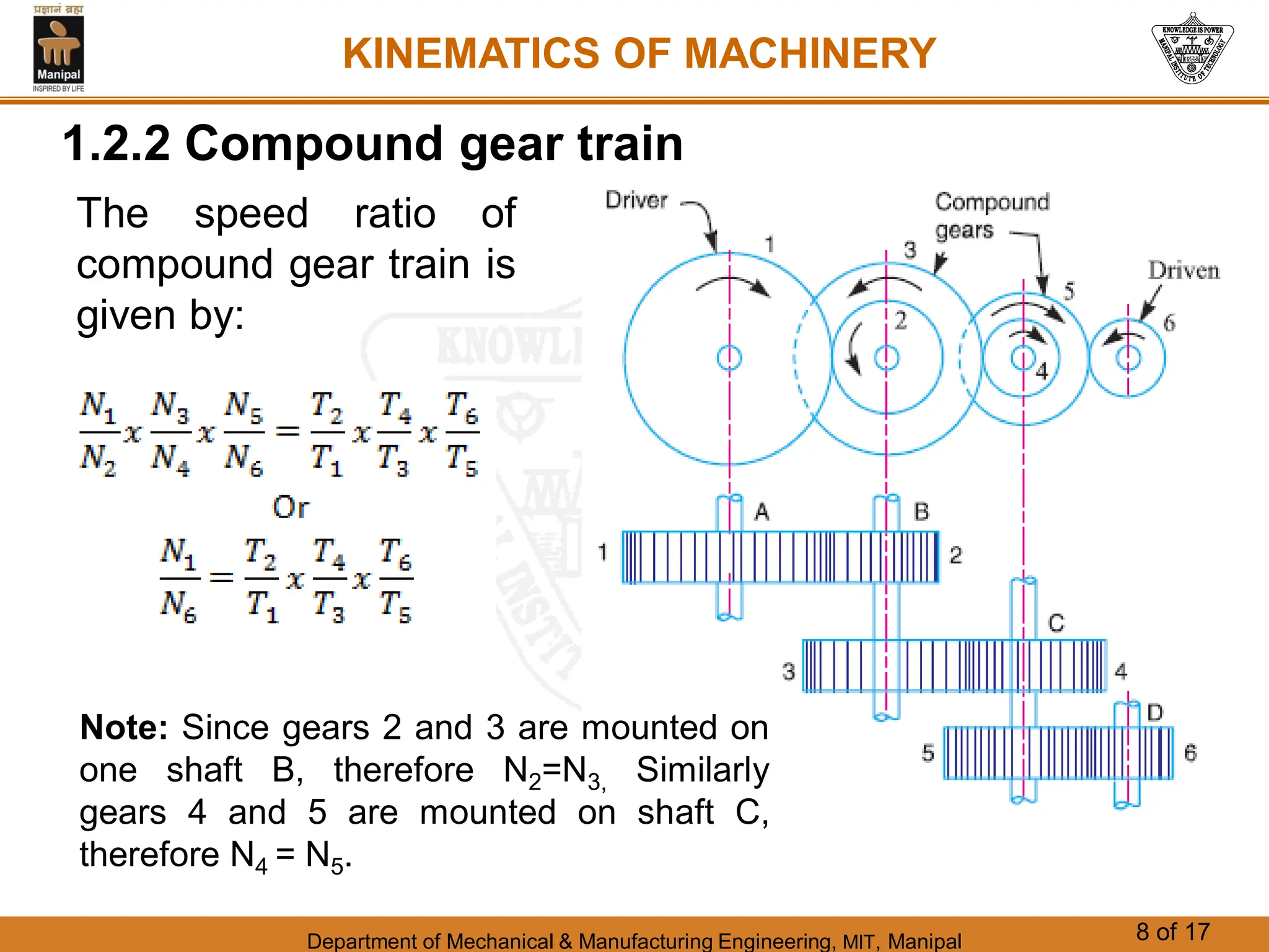
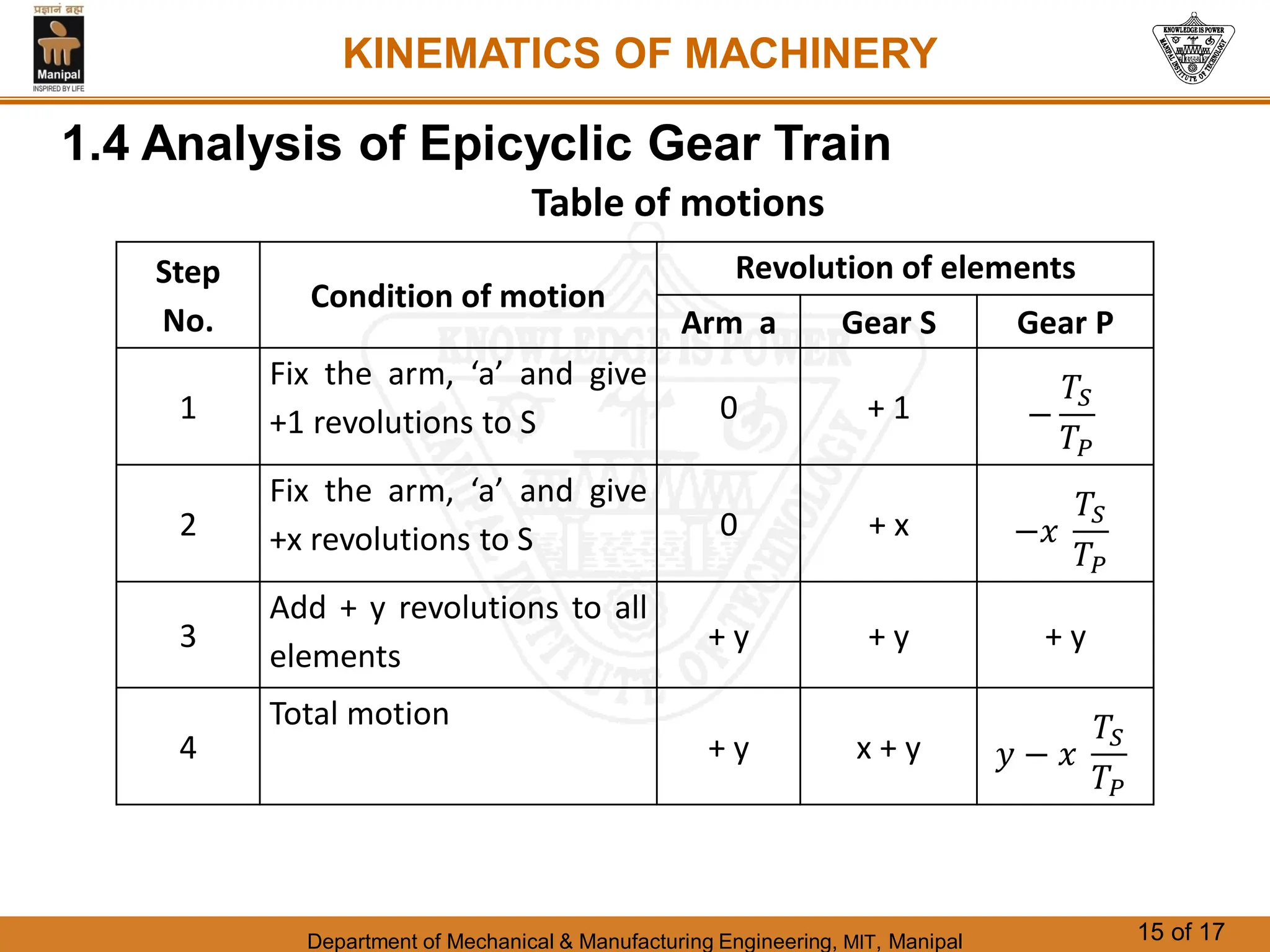
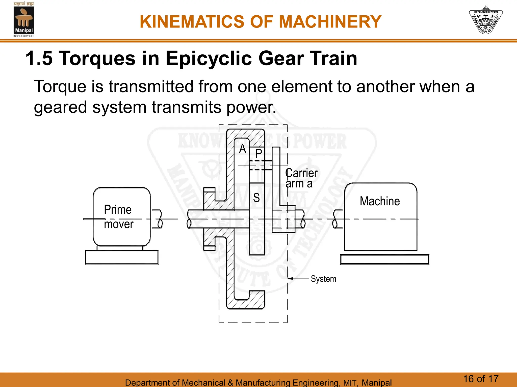
Department of Mechanical & Manufacturing Engineering, MIT, Manipal 1 of 17
CHAPTER 5
GEAR TRAIN
KINEMATICS OF MACHINERY
Department of Mechanical & Manufacturing Engineering, MIT, Manipal 2 of 17
KINEMATICS OF MACHINERY
1.1 Introduction
 When two or more gears are made to mesh
with each other to transmit power from one
shaft to another such a combination is called
gear train.
 The nature of the train used depends upon
the velocity ratio required and the relative
position of the axes of shafts.
 A gear train may consist of spur and spiral
gears.
Department of Mechanical & Manufacturing Engineering, MIT, Manipal 3 of 17
KINEMATICS OF MACHINERY
1.2 Types of Gear Train
 Depending upon the arrangement of wheels
the different types of gear train are as follows:
1.Simple gear train
2.Compound gear train
3.Reverted gear train
4.Epicyclic gear train
Department of Mechanical & Manufacturing Engineering, MIT, Manipal 4 of 17
KINEMATICS OF MACHINERY
1.2 Types of Gear Train
 In the first three types of gear trains, the axes of
the shafts over which the gears are mounted are
fixed relative to each other.
 But in case of epicyclic gear trains, the axes of
the shafts on which the gears are mounted may
move relative to a fixed axis.
Department of Mechanical & Manufacturing Engineering, MIT, Manipal 5 of 17
KINEMATICS OF MACHINERY
1.2.1 Simple gear train
Figure (a).
Department of Mechanical & Manufacturing Engineering, MIT, Manipal 6 of 17
KINEMATICS OF MACHINERY
1.2.1 Simple gear train
Figure (b).
Department of Mechanical & Manufacturing Engineering, MIT, Manipal 7 of 17
KINEMATICS OF MACHINERY
1.2.1 Simple gear train
Figure (c). What is the Speed ratio ?
Department of Mechanical & Manufacturing Engineering, MIT, Manipal 8 of 17
KINEMATICS OF MACHINERY
1.2.2 Compound gear train
The speed ratio of
compound gear train is
given by:
Note: Since gears 2 and 3 are mounted on
one shaft B, therefore N2=N3, Similarly
gears 4 and 5 are mounted on shaft C,
therefore N4 = N5.
Department of Mechanical & Manufacturing Engineering, MIT, Manipal 9 of 17
KINEMATICS OF MACHINERY
1.2.3 Reverted gear train
Department of Mechanical & Manufacturing Engineering, MIT, Manipal 10 of 17
KINEMATICS OF MACHINERY
1.2.4 Epicyclic gear train
The epicyclic gear trains are useful for transmitting high
velocity ratios with gears of moderate size in a
comparatively lesser space.
Department of Mechanical & Manufacturing Engineering, MIT, Manipal 11 of 17
KINEMATICS OF MACHINERY
1.3 Automobile Differential Mechanism
Function is to,
(a) Transmit motion from the engine shaft to the rear driving
wheels, and
(b) Rotate the rear wheels at different speeds while the
automobile is taking a turn.
Department of Mechanical & Manufacturing Engineering, MIT, Manipal 12 of 17
KINEMATICS OF MACHINERY
1.3 Automobile Differential Mechanism
Department of Mechanical & Manufacturing Engineering, MIT, Manipal 13 of 17
KINEMATICS OF MACHINERY
1.3 Automobile Differential Mechanism
Table of motions
Step
No.
Condition of motion
Revolution of elements
Gear B Gear C Gear E Gear D
1
Gear B fixed-Gear C rotated
through +1 revolutions (anti
-clockwise) 0 + 1 +
𝑇𝑐
𝑇𝐸
−
𝑇𝑐
𝑇𝐸

𝑇𝐸
𝑇𝐷
= −1
(𝑇𝐶 = 𝑇𝐷)
2
Gear B fixed-Gear C rotated
through + x revolutions
0 + x +𝑥
𝑇𝑐
𝑇𝐸
- x
3
Add + y revolutions to all
elements
+ y + y + y + y
4
Total motion
+ y x + y 𝑦 + 𝑥
𝑇𝑐
𝑇𝐸
y - x
Department of Mechanical & Manufacturing Engineering, MIT, Manipal 14 of 17
KINEMATICS OF MACHINERY
1.4 Analysis of Epicyclic Gear Train
S
P
arm a
Carrier
S
p
a
Epicyclic trains usually have complex motions.
Therefore, comparatively simple methods are used
to analyze them which do not require accurate
visualization of the motions.
Department of Mechanical & Manufacturing Engineering, MIT, Manipal 15 of 17
KINEMATICS OF MACHINERY
1.4 Analysis of Epicyclic Gear Train
Step
No.
Condition of motion
Revolution of elements
Arm a Gear S Gear P
1
Fix the arm, ‘a’ and give
+1 revolutions to S 0 + 1 −
𝑇𝑆
𝑇𝑃
2
Fix the arm, ‘a’ and give
+x revolutions to S 0 + x −𝑥
𝑇𝑆
𝑇𝑃
3
Add + y revolutions to all
elements
+ y + y + y
4
Total motion
+ y x + y 𝑦 − 𝑥
𝑇𝑆
𝑇𝑃
Table of motions
Department of Mechanical & Manufacturing Engineering, MIT, Manipal 16 of 17
KINEMATICS OF MACHINERY
1.5 Torques in Epicyclic Gear Train
Torque is transmitted from one element to another when a
geared system transmits power.
A
S
P
arm a
Carrier
Machine
Prime
mover
System
Department of Mechanical & Manufacturing Engineering, MIT, Manipal 17 of 17
KINEMATICS OF MACHINERY
Numericals from
Chapter : Gear Train
End of Chapter

Gear Train.pdf .

  • 1.
    Department of Mechanical& Manufacturing Engineering, MIT, Manipal 1 of 17 CHAPTER 5 GEAR TRAIN KINEMATICS OF MACHINERY
  • 2.
    Department of Mechanical& Manufacturing Engineering, MIT, Manipal 2 of 17 KINEMATICS OF MACHINERY 1.1 Introduction  When two or more gears are made to mesh with each other to transmit power from one shaft to another such a combination is called gear train.  The nature of the train used depends upon the velocity ratio required and the relative position of the axes of shafts.  A gear train may consist of spur and spiral gears.
  • 3.
    Department of Mechanical& Manufacturing Engineering, MIT, Manipal 3 of 17 KINEMATICS OF MACHINERY 1.2 Types of Gear Train  Depending upon the arrangement of wheels the different types of gear train are as follows: 1.Simple gear train 2.Compound gear train 3.Reverted gear train 4.Epicyclic gear train
  • 4.
    Department of Mechanical& Manufacturing Engineering, MIT, Manipal 4 of 17 KINEMATICS OF MACHINERY 1.2 Types of Gear Train  In the first three types of gear trains, the axes of the shafts over which the gears are mounted are fixed relative to each other.  But in case of epicyclic gear trains, the axes of the shafts on which the gears are mounted may move relative to a fixed axis.
  • 5.
    Department of Mechanical& Manufacturing Engineering, MIT, Manipal 5 of 17 KINEMATICS OF MACHINERY 1.2.1 Simple gear train Figure (a).
  • 6.
    Department of Mechanical& Manufacturing Engineering, MIT, Manipal 6 of 17 KINEMATICS OF MACHINERY 1.2.1 Simple gear train Figure (b).
  • 7.
    Department of Mechanical& Manufacturing Engineering, MIT, Manipal 7 of 17 KINEMATICS OF MACHINERY 1.2.1 Simple gear train Figure (c). What is the Speed ratio ?
  • 8.
    Department of Mechanical& Manufacturing Engineering, MIT, Manipal 8 of 17 KINEMATICS OF MACHINERY 1.2.2 Compound gear train The speed ratio of compound gear train is given by: Note: Since gears 2 and 3 are mounted on one shaft B, therefore N2=N3, Similarly gears 4 and 5 are mounted on shaft C, therefore N4 = N5.
  • 9.
    Department of Mechanical& Manufacturing Engineering, MIT, Manipal 9 of 17 KINEMATICS OF MACHINERY 1.2.3 Reverted gear train
  • 10.
    Department of Mechanical& Manufacturing Engineering, MIT, Manipal 10 of 17 KINEMATICS OF MACHINERY 1.2.4 Epicyclic gear train The epicyclic gear trains are useful for transmitting high velocity ratios with gears of moderate size in a comparatively lesser space.
  • 11.
    Department of Mechanical& Manufacturing Engineering, MIT, Manipal 11 of 17 KINEMATICS OF MACHINERY 1.3 Automobile Differential Mechanism Function is to, (a) Transmit motion from the engine shaft to the rear driving wheels, and (b) Rotate the rear wheels at different speeds while the automobile is taking a turn.
  • 12.
    Department of Mechanical& Manufacturing Engineering, MIT, Manipal 12 of 17 KINEMATICS OF MACHINERY 1.3 Automobile Differential Mechanism
  • 13.
    Department of Mechanical& Manufacturing Engineering, MIT, Manipal 13 of 17 KINEMATICS OF MACHINERY 1.3 Automobile Differential Mechanism Table of motions Step No. Condition of motion Revolution of elements Gear B Gear C Gear E Gear D 1 Gear B fixed-Gear C rotated through +1 revolutions (anti -clockwise) 0 + 1 + 𝑇𝑐 𝑇𝐸 − 𝑇𝑐 𝑇𝐸  𝑇𝐸 𝑇𝐷 = −1 (𝑇𝐶 = 𝑇𝐷) 2 Gear B fixed-Gear C rotated through + x revolutions 0 + x +𝑥 𝑇𝑐 𝑇𝐸 - x 3 Add + y revolutions to all elements + y + y + y + y 4 Total motion + y x + y 𝑦 + 𝑥 𝑇𝑐 𝑇𝐸 y - x
  • 14.
    Department of Mechanical& Manufacturing Engineering, MIT, Manipal 14 of 17 KINEMATICS OF MACHINERY 1.4 Analysis of Epicyclic Gear Train S P arm a Carrier S p a Epicyclic trains usually have complex motions. Therefore, comparatively simple methods are used to analyze them which do not require accurate visualization of the motions.
  • 15.
    Department of Mechanical& Manufacturing Engineering, MIT, Manipal 15 of 17 KINEMATICS OF MACHINERY 1.4 Analysis of Epicyclic Gear Train Step No. Condition of motion Revolution of elements Arm a Gear S Gear P 1 Fix the arm, ‘a’ and give +1 revolutions to S 0 + 1 − 𝑇𝑆 𝑇𝑃 2 Fix the arm, ‘a’ and give +x revolutions to S 0 + x −𝑥 𝑇𝑆 𝑇𝑃 3 Add + y revolutions to all elements + y + y + y 4 Total motion + y x + y 𝑦 − 𝑥 𝑇𝑆 𝑇𝑃 Table of motions
  • 16.
    Department of Mechanical& Manufacturing Engineering, MIT, Manipal 16 of 17 KINEMATICS OF MACHINERY 1.5 Torques in Epicyclic Gear Train Torque is transmitted from one element to another when a geared system transmits power. A S P arm a Carrier Machine Prime mover System
  • 17.
    Department of Mechanical& Manufacturing Engineering, MIT, Manipal 17 of 17 KINEMATICS OF MACHINERY Numericals from Chapter : Gear Train End of Chapter