Downloaded 260 times


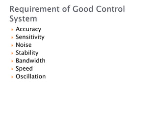


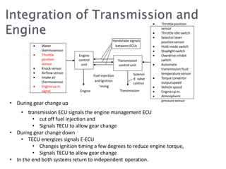
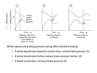
![• Inlet manifold absolute pressure (MAP) sensor has an important role
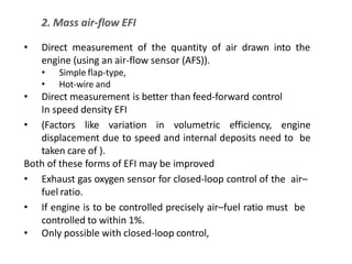
• Fuel injection opening period or pulse width is related directly to the
mass of air flowing into the engine as fuel-air ratio must be maintained
constant in steady-state operation
• And the mass of air-flow is related to the manifold absolute pressure
by the equation
• where Vd is the displacement of the cylinder,
• nv is the volumetric efficiency or the fraction of Vd actually filled on
each stroke, [= f(speed)]
• pi is manifold absolute pressure,
• R is a constant and
• Ti is the intake air temperature.
am
RTi
Vd nv Pi](https://image.slidesharecdn.com/gensemi2-170611181643/85/CONTROL-SYSTEMS-IN-AUTOMOBILES-13-320.jpg)
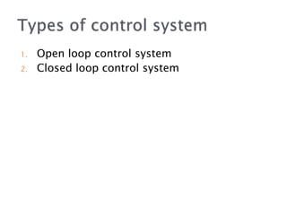
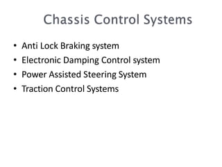
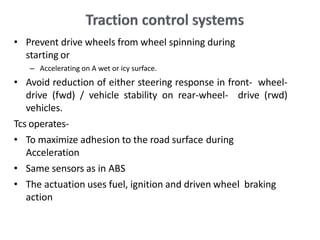
![• The objective of low exhaust-gas
emission levels
• Maintain the air–fuel ratio at 14.7:1
[stoichiometrically / chemically perfect]
• Three-way catalytic converters to control
emission](https://image.slidesharecdn.com/gensemi2-170611181643/85/CONTROL-SYSTEMS-IN-AUTOMOBILES-15-320.jpg)


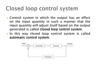
The document outlines control systems, emphasizing their necessity for automation in modern technology. It describes open loop and closed loop control systems, detailing their functions with examples like electric hand driers and automatic washing machines. Furthermore, it explores more complex automotive systems, such as fuel injection and anti-lock braking systems, which utilize sensors and actuators to optimize performance and safety.


![Engine management system[ EMS ] or Engine Control Unit [ ECU ]](https://cdn.slidesharecdn.com/ss_thumbnails/enginemanagementsystem-170920182131-thumbnail.jpg?width=640&height=640&fit=bounds)


