Downloaded 2,144 times

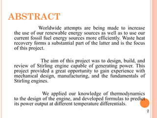


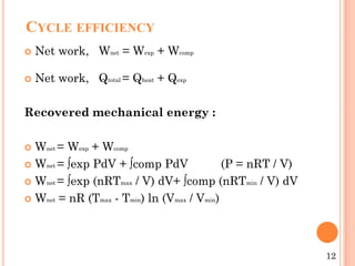
![Provided heat :
Qexp = ∫exp PdV
Qexp = nR Tmax ln(Vmax / Vmin )
Qheat = nCv (Tmax - Tmin)
Qtotal = nCv (Tmax - Tmin) + nR Tmax ln (Vmax / Vmin)
Cycle efficiency :
η = [R (Tmax - Tmin) ln (Vmax / Vmin)] / [Cv (Tmax - Tmin) + R Tmax ln
(Vmax / Vmin)]
13](https://image.slidesharecdn.com/ppt10-141217122719-conversion-gate01/85/stirling-engine-ppt-15-320.jpg)


![REFERENCES
[1] Institute of Engineering Thermo physics, Chinese
Academy of Sciences, No. 11, BeiSiHuanXi Road, Beijing
100190, China Beijing ShiYanTianQiang Technology ompany,
Beijing 100076, Chin Received 20 July 2011
[2] Department of Mechanical Technology, Faculty of
Technical Education, Gazi University, 06500 Teknikokullar,
Ankara, Turkey,( Received 30 October 2007)
[3] Department of Mechanical Technology, Faculty of
Technical Education, Gazi University, Besevler, 06500,
Ankara, Turkey Received 16 July 2007,
[4]. Wikipedia free encyclopedia. Stirling engine,
www.wikipedia.org/wiki/stirlin-engine, (02/18/2009)
[5] stirling cycle efficiency
http://www.robertstirlingengine.com/alpha_uk.php
26](https://image.slidesharecdn.com/ppt10-141217122719-conversion-gate01/85/stirling-engine-ppt-28-320.jpg)


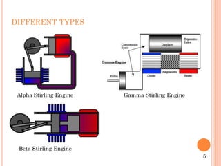
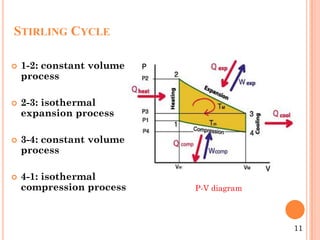
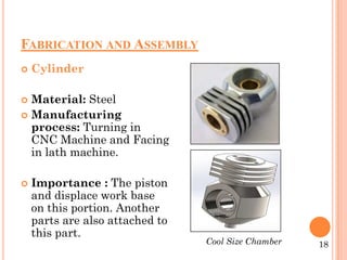
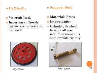
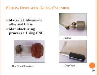
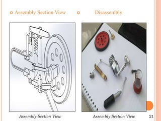
This document presents a project report on designing and building a working model of a Stirling engine. It includes sections on the abstract, introduction, literature review, methodology, setup and preparation, and conclusion. The introduction provides a brief history of the Stirling engine and its different types. The methodology section explains the Stirling thermodynamic cycle and calculations for cycle efficiency. The setup and preparation section details the fabrication and assembly of engine components like the cylinder, piston, displacer, and flywheel. The conclusion recognizes areas for further improvement, such as addressing friction and leakage issues to increase useful work output.


