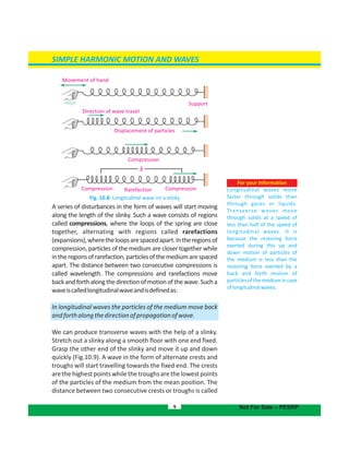
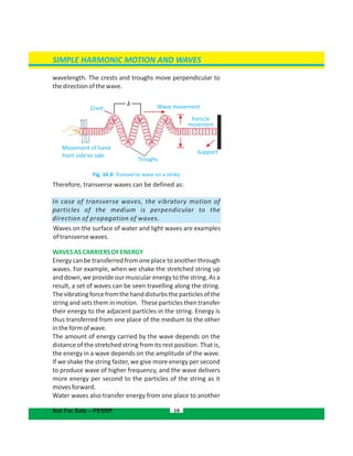
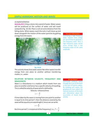
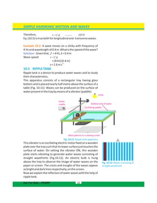
The document discusses simple harmonic motion and waves. It defines simple harmonic motion (SHM) as oscillatory motion where the net force is directly proportional to displacement from the mean position and directed towards the mean position. Examples of SHM include a mass attached to a spring, a ball in a bowl, and a pendulum. Key characteristics of SHM are outlined. The document also introduces different types of waves and their properties.

![GEOMETRICAL OPTICS
Example 12.3: A ray of light enters from air into glass. The
o
angleofincidenceis30 .Iftherefractiveindexofglassis1.52,
thenfindtheangleofrefraction‘r’.
Solution:
o
Giventhat,i=30 ,n=1.52
UsingSnell'slaw,
o
1.52 sin r = sin 30
o
or sin r = sin 30 /1.52
sin r = 0.33
-1
r = sin (0.33)
o
r = 19.3
o
Hence, angle of refraction is 19.3 .
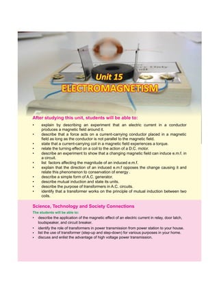
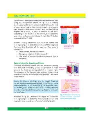
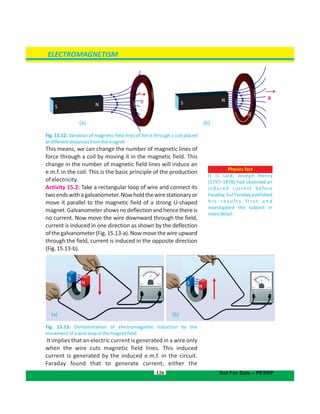
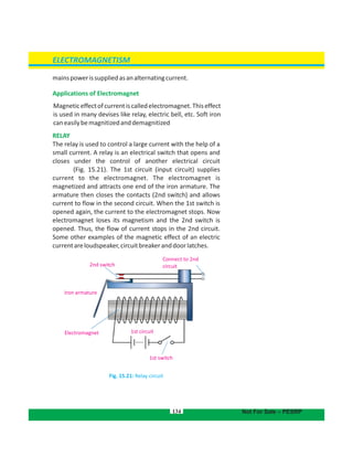
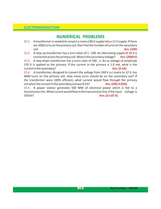
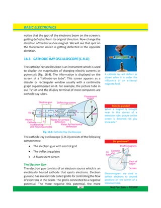
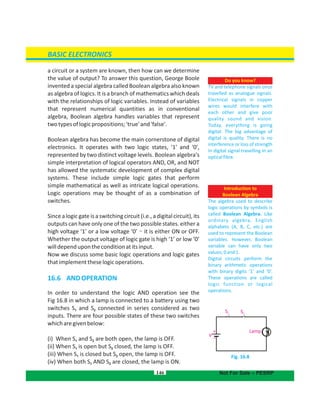
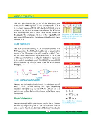
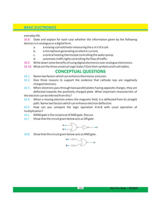
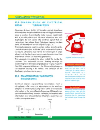
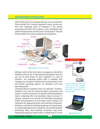
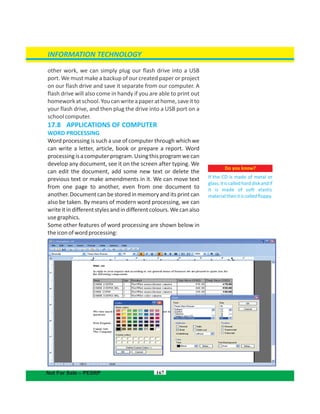
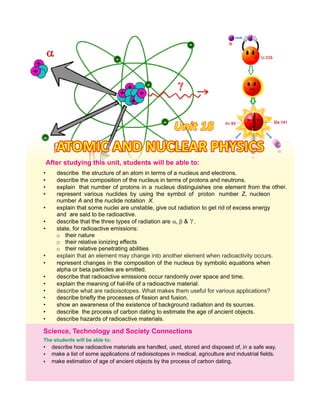
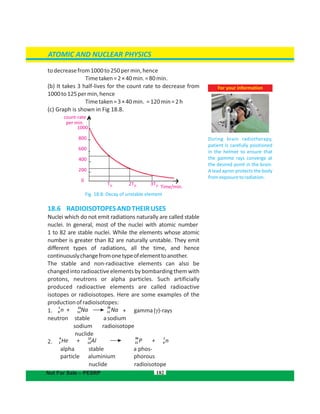
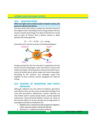
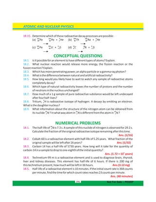
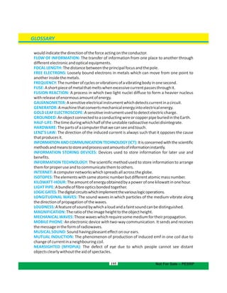
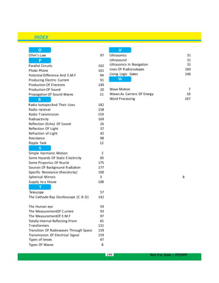
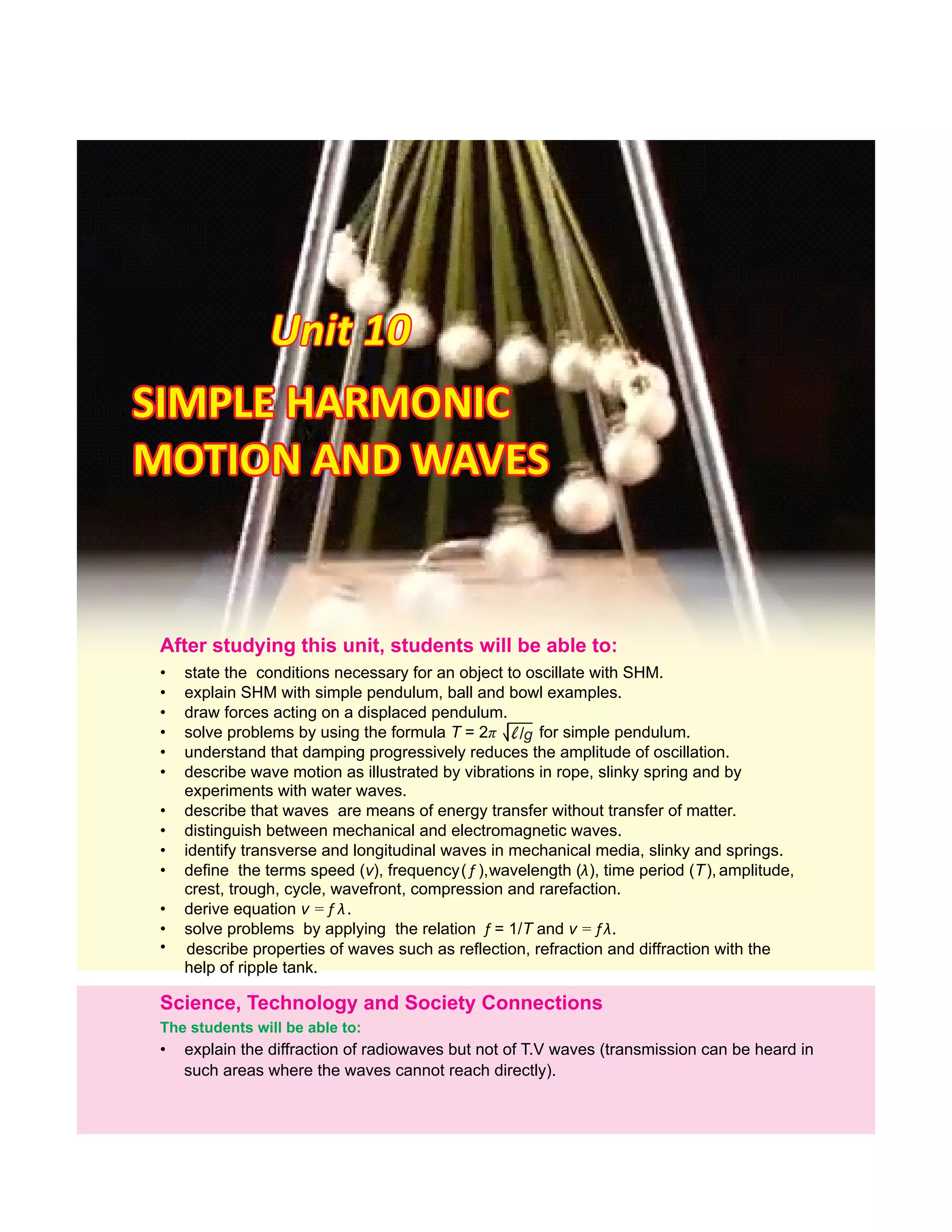
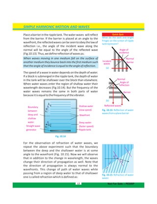
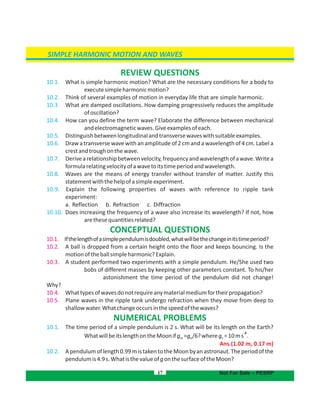
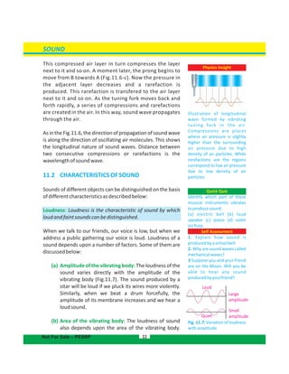
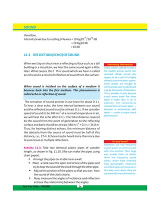
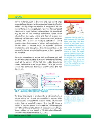
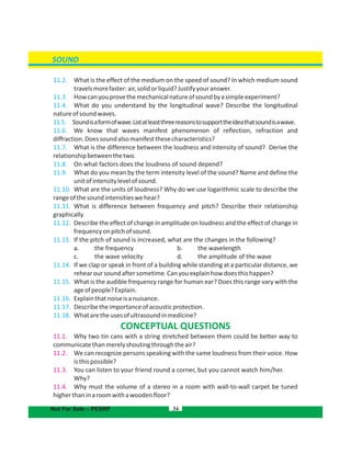
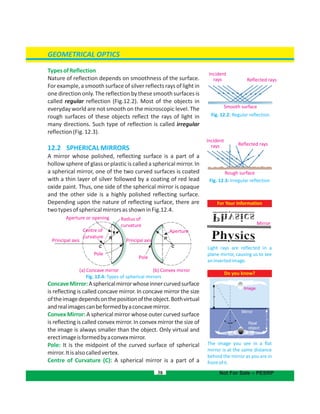
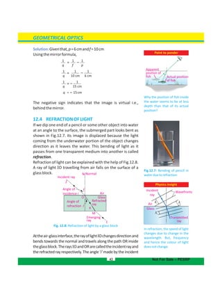
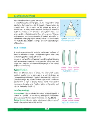
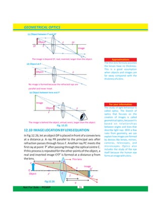
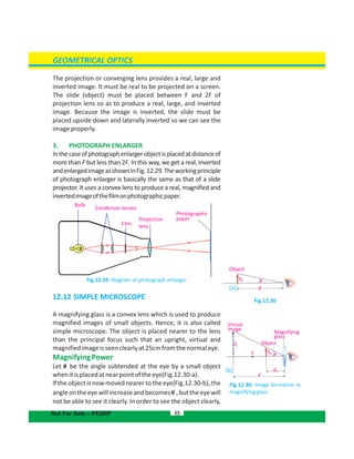
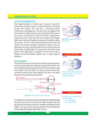
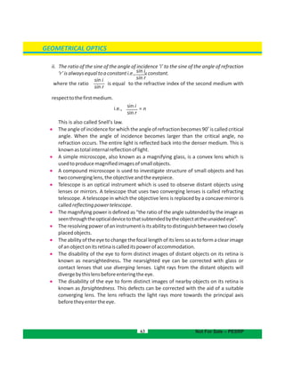
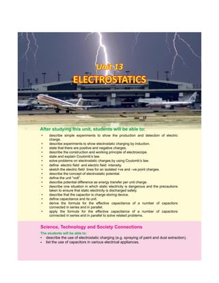
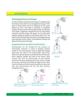
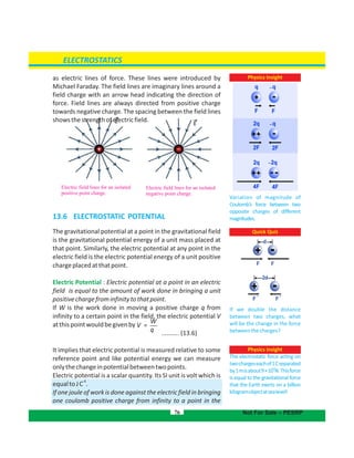
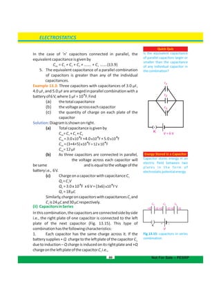
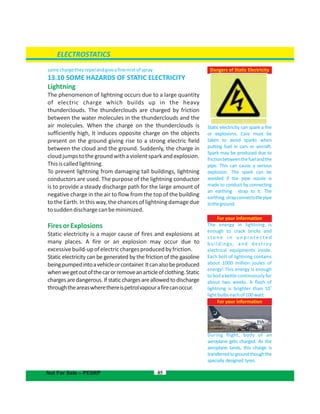
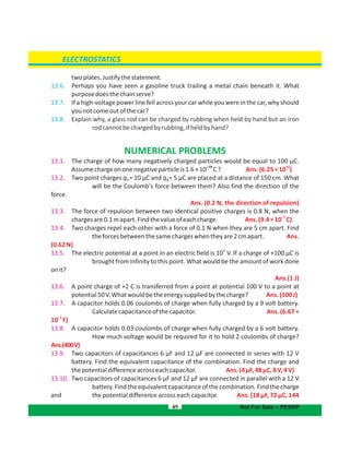
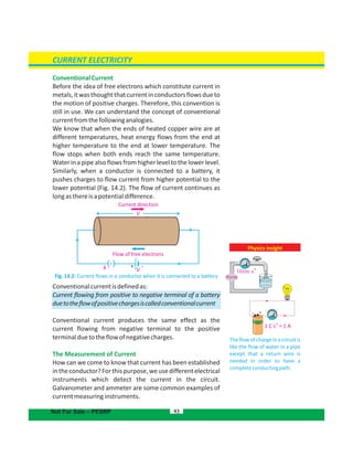
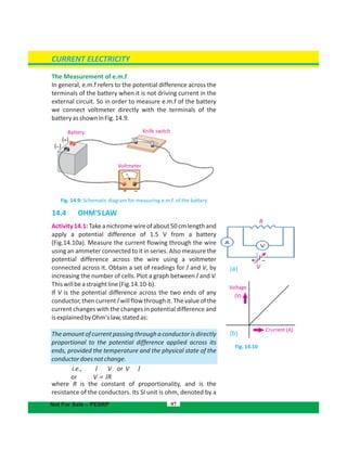
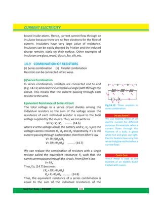
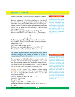
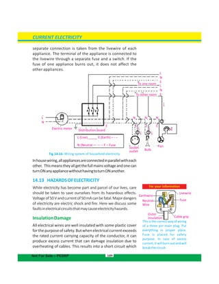
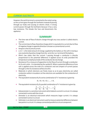
12.5 TOTAL INTERNAL REFLECTION
When a ray of light travelling in denser medium enters into a
rarer medium, it bends away from the normal (Fig.12.9-a). If
the angle of incidence ‘i’ increases, the angle of refraction ‘r’
also increases. For a particular value of the angle of
o
incidence, the angle of refraction becomes 90 . The angle of
incidence, that causes the refracted ray in the rarer medium
o
to bend through 90 is called critical angle (Fig.12.9-b). When
the angle of incidence becomes larger than the critical angle,
no refraction occurs. The entire light is reflected back into the
denser medium (Fig.12.9-c). This is known as total internal
reflectionoflight.
Example 12.4: Find the value of critical angle for water
o
(refracted angle = 90 ). The refractive index of water is 1.33
andthatofairis1.
Solution: When light enters in air from water, Snell's law
becomes
or n sin i = sin r
o
n sin i = sin 90
n sin i = 1
But n = 1.33
Therefore,
-1
i = sin [1/1.33]
o
or =
-1
sin (0.752) = 48.8
o
Critical angle 48.8C =
o
Therefore, critical angle of water is 48.8 .
44 Not For Sale – PESRP
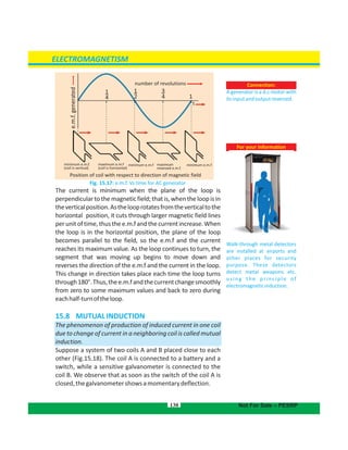
(a)
(b)
(c)
Fig. 12.9: for totalCondition
internalreflection
Air No refracted ray
Reflected
ray
Incident
ray
i > c
i
Glass
i = c
Incident
ray
Air 90
o
Refracted ray
i
Glass
Normal
N
Refracted ray
Air
Incident
ray
i
Glass
i >c
r
sin i
sin r
sin r
sin i
= n
= n](https://image.slidesharecdn.com/physics-10-191026135046/85/Physics-10-44-320.jpg)
![GEOMETRICAL OPTICS
10cm)
12.2. An object 30 cm tall is located 10.5 cm from a concave mirror with focal length
16cm.(a)Whereistheimagelocated?(b)Howhighisit?
Ans. [ (a) 30.54 cm (b) 87.26 cm]
12.3. An object and its image in a concave mirror are of the same height, yet inverted,
whentheobjectis20cmfromthemirror.Whatisthefocallengthofthemirror?
Ans. (10 cm)
12.4. Find the focallength of a mirror that forms an image5.66cm behind the mirror of an
objectplacedat34.4cminfrontofthemirror.Isthemirrorconcaveorconvex?
Ans. (-6.77 cm, )Convex mirror
12.5. An image of a statue appears to be 11.5 cm behind a concave mirror with focal
length13.5cm.Findthedistancefromthestatuetothemirror. Ans.(77.62cm)
12.6. An image is produced by a concave mirror of focal length 8.7 cm. The object is
13.2 cm tall and at a distance 19.3 cm from the mirror. (a) Find the location and
of the image. (b) Find the height of the image produced by theheight
mirroriftheobjectistwiceasfarfromthemirror.
Ans. [(a) 10.83 cm (b) 5.42 cm]15.84 cm,
12.7. Nabeela uses a concave mirror when applying makeup. The mirror has a radius of
curvature of 38 cm. (a) What is the focal length of the mirror? (b) Nabeela is
located 50 cm from the mirror. Where will her image appear? (c) Will the
imagebe uprightorinverted? Ans. [(a) 19 cm, (b)
30.64cm, (c)upright]
12.8. Anobject4cmhighisplacedatadistanceof12cmfromaconvexlensoffocallength
8cm.Calculatethepositionandsizeoftheimage.Alsostatethenatureoftheimage.
Ans. (24 cm, 8 cm, image is real, inverted and magnified)
12.9. An object 10 cm high is placed at a distance of 20 cm from a concave lens of focal
length 15 cm. Calculate the position and size of the image. Also, state the
natureof theimage. Ans. (-8.57 cm, 4.28 cm, image is virtual, erect
anddiminished)
12.10. A convex lens of focal length 6 cm is to be used to form a virtual image three times
thesizeoftheobject.Wheremustthelensbeplaced? Ans.
(4cm)
12.11.
o
A ray of light from air is incident on a liquid surface at an angle of incidence 35 .
Calculatetheangleofrefractioniftherefractiveindexoftheliquidis1.25.Also
calculatethecriticalanglebetweentheliquidairinter-face. Ans.
o o
(27.31 ,53.13 )
12.12. The power of a convex lens is 5 D. At what distance the object should be placed from
thelenssothatitsrealand2timeslargerimageisformed. Ans.
(30cm)
67 Not For Sale – PESRP](https://image.slidesharecdn.com/physics-10-191026135046/85/Physics-10-67-320.jpg)

![116
14.7. Howmanywatt-hoursaretherein1000joules?
14.8. From your experience in watching cars on the roads at night, are automobile
headlampsconnectedinseriesorinparallel.
14.9. A certain flash-light can use a 10 ohm bulb or a 5 ohm bulb. Which bulb should be
usedtogetthebrighterlight?Whichbulbwilldischargethebatteryfirst?
14.10. Itisimpracticabletoconnectanelectricbulbandanelectricheaterinseries.Why?
14.11. Doesafuseinacircuitcontrolthepotentialdifferenceorthecurrent?
NUMERICAL PROBLEMS
14.1. A current of 3 mA is flowing through a wire for 1 minute. What is the charge flowing
throughthewire? Ans. (180
-3
×10 C)
14.2. At100,000Ω,howmuchcurrentflowsthroughyourbodyifyoutouchtheterminalsof
a 12 V battery? If your skin is wet, so that your resistance is only 1000 Ω, how
muchcurrentwouldyoureceivefromthesamebattery?
-4
Ans.(1.2×10 A,1.2
-2
×10 A)
14.3. The resistance of a conductor wire is 10 MΩ. If a potential difference of 100 volts is
appliedacrossitsends,thenfindthevalueofcurrentpassingthroughitinmA.
Ans. ( 0.01 mA)
14.4. By applying a potential difference of 10 V across a conductor, a current of 1.5 A passes
throughit.Howmuchenergywouldbeobtainedfromthecurrentin2minutes?
Ans.(1800 J)
14.5. Two resistances of 2 kΩ and 8 kΩ are joined in series, if a 10 V battery is connected
acrosstheendsofthiscombination,findthefollowingquantities:
(a) Theequivalentresistanceoftheseriescombination.
(b) Currentpassingthrougheachoftheresistances.
(c) Thepotentialdifferenceacrosseachresistance.
Ans. [(a) 10 kΩ (b) 1 mA (c) 2 V, 8 V]
14.6. Two resistances of 6 k and 12 kΩ are connected in parallel. A 6 V battery isΩ
connectedacrossitsends,findthevaluesofthefollowingquantities:
(a) Equivalentresistanceoftheparallelcombination.
(b) Currentpassingthrougheachoftheresistances.
(c) Potentialdifferenceacrosseachoftheresistance.
Ans. [(a) 4 kΩ, (b) 1 mA,0.5 mA (c) 6 V]
14.7. An electric bulb is marked with 220 V, 100 W. Find the resistance of the filament of
the bulb. If the bulb is used 5 hours daily, find the energy in kilowatt-hour
consumed bythebulbinonemonth(30days). Ans.(484 ,15Ω
kWh)
14.8. An incandescent light bulb with an operating resistance of 95 Ω is labelled “150 W.”
CURRENT ELECTRICITY
Not For Sale – PESRP](https://image.slidesharecdn.com/physics-10-191026135046/85/Physics-10-116-320.jpg)
![117
Isthisbulbdesignedforuseina120Vcircuitora220Vcircuit?
Ans. (It has been designed for 120 V)
14.9. Ahouseisinstalledwith
(a) 10bulbsof60Weachofwhichareused5hoursdaily.
(b) 4fansof75Weachofwhichrun10hoursdaily.
(c) OneT.V.of100Wwhichisusedfor5hoursdaily.
(d) Oneelectricironof1000Wwhichisusedfor2hoursdaily.
If the cost of one unit of electricity is Rs.4. Find the monthly expenditure of
electricity(onemonth=30days). Ans. (Rs.
1020/-)
14.10. A 100 W lamp bulb and a 4 kW water heater are connected to a 250 V supply.
Calculate (a) the current which flows in each appliance (b) the resistance of each
appliancewheninuse. Ans.[(a)0.4A,16A(b)625Ω,15.62Ω]
14.11. A resistor of resistance 5.6 Ω is connected across a battery of 3.0 V by means of a
wire of negligible resistance. A current of 0.5 A passes through the resistor.
Calculate
(a) Powerdissipatedintheresistor.
(b) Totalpowerproducedbythebattery.
(c) Givethereasonofdifferencebetweenthesetwoquantities.
Ans. [(a)1.4W (b)1.5W
(c)somepowerislostbytheinternalresistanceofthebattery]
CURRENT ELECTRICITY
Not For Sale – PESRP](https://image.slidesharecdn.com/physics-10-191026135046/85/Physics-10-117-320.jpg)