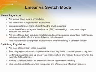
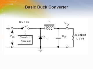
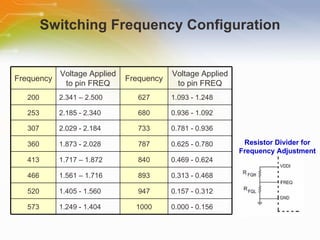
Fully Integrated Switch-Mode Power Regulators Source: FREESCALE
Introduction Purpose This training module introduces the MC3471x switch mode power supplies and their applications. Outline Basic buck converter Key features of the MC3471x regulators Internal functional block diagram Protection functions Typical application diagram Content 13 pages Duration 10 Minutes
SMARTMOS Power Technology Highly capable  — providing full flexibility of integration  Robust  — developed for applications demanding a high level of environmental tolerance, required in automotive and industrial applications.  Cost-effective  — appropriately balanced analog, power and CMOS logic (SMARTMOS) capabilities providing cost-effective solutions  Innovatively packaged  — Freescale's innovative multi-die packaging options exploit strengths of both SMARTMOS and HDTMOS technologies to offer reduced cost and space.  Constantly improving  — Freescale continues to evolve SMARTMOS to meet the world’s needs.
Linear vs Switch Mode Linear Regulators Are a more direct means of regulation Are the easiest to implement in applications Series regulators are more efficient than the shunt regulators No radiated Electro-Magnetic Interference (EMI) since no high current switching or inductors are involved Are less efficient than switching regulators and generate greater amounts of heat than do switching regulators for the same delivered output current Find application in lower power applications or where efficiency is of lesser concern Switching Regulators Are more efficient than linear regulators Switching regulators transform power while linear regulators consume power to regulate. Switching regulators store-up energy in a magnetic field and recover the energy when the magnetic field collapses Radiate considerable EMI as a result of inductor high current switching Most used in applications where high power and efficiency are of primary concern.
Basic Buck Converter
MC3471x Switch Mode Regulators Input operating voltage 3.0 – 6.0V 1 MHz synchronous single and dual switching regulators Programmable switching frequency 200 KHz–1 MHz Integrated MOSFETs 5A sourcing / 3A sink/source Output voltage +/-2% accuracy Adjustable output 0.7 – 3.6V Separate VREF output +/-2% accuracy PGOOD and shutdown inputs (active low) Soft start — all outputs Extensive protection Overvoltage, undervoltage, over current, short circuit and thermal Programmable over current limit MC34712/3/6/7
Applications MC34713 & MC34717 Portable electronics Digital still cameras PDAs Battery-based handheld devices Servers Game consoles Networking MC34712 & MC34716 Graphic cards Servers Set top boxes Game consoles FPGAs Networking PCs TVs
Functional Block Diagram
Operational Modes MC34712/6 Only
Switching Frequency Configuration Resistor Divider for Frequency Adjustment Frequency Voltage Applied to pin FREQ Frequency Voltage Applied to pin FREQ 200 2.341 – 2.500 627 1.093 - 1.248 253 2.185 - 2.340 680 0.936 - 1.092 307 2.029 - 2.184 733 0.781 - 0.936 360 1.873 - 2.028 787 0.625 - 0.780 413 1.717 – 1.872 840 0.469 - 0.624 466 1.561 – 1.716 893 0.313 - 0.468 520 1.405 - 1.560 947 0.157 - 0.312 573 1.249 - 1.404 1000 0.000 - 0.156
Protection and Diagnostic Features Output Overvoltage The output voltage goes higher than the rising overvoltage threshold.  Output Undervoltage The output voltage falls below the falling undervoltage threshold. Output Over Current This block detects over current in the Power MOSFETs of the buck converter.  Short Circuit Current Limit If the load current reaches the ISHORT value, the device reacts by shutting down the output immediately.   Thermal Shutdown Thermal limit detection block monitors the temperature of the device and protects against excessive heating.
MC34712 Simplified Application Diagram
MC34713 Simplified Application Diagram
Additional Resource For ordering the MC3471x regulators, please click the part list or Call our sales hotline For additional inquires contact our technical service hotline For more product information go to http://www.freescale.com/webapp/sps/site/taxonomy.jsp?nodeId=0174403526 Newark Farnell

Fully Integrated Switch-Mode Power Regulators

  • 1.
    Fully Integrated Switch-ModePower Regulators Source: FREESCALE
  • 2.
    Introduction Purpose Thistraining module introduces the MC3471x switch mode power supplies and their applications. Outline Basic buck converter Key features of the MC3471x regulators Internal functional block diagram Protection functions Typical application diagram Content 13 pages Duration 10 Minutes
  • 3.
    SMARTMOS Power TechnologyHighly capable — providing full flexibility of integration Robust — developed for applications demanding a high level of environmental tolerance, required in automotive and industrial applications. Cost-effective — appropriately balanced analog, power and CMOS logic (SMARTMOS) capabilities providing cost-effective solutions Innovatively packaged — Freescale's innovative multi-die packaging options exploit strengths of both SMARTMOS and HDTMOS technologies to offer reduced cost and space. Constantly improving — Freescale continues to evolve SMARTMOS to meet the world’s needs.
  • 4.
    Linear vs SwitchMode Linear Regulators Are a more direct means of regulation Are the easiest to implement in applications Series regulators are more efficient than the shunt regulators No radiated Electro-Magnetic Interference (EMI) since no high current switching or inductors are involved Are less efficient than switching regulators and generate greater amounts of heat than do switching regulators for the same delivered output current Find application in lower power applications or where efficiency is of lesser concern Switching Regulators Are more efficient than linear regulators Switching regulators transform power while linear regulators consume power to regulate. Switching regulators store-up energy in a magnetic field and recover the energy when the magnetic field collapses Radiate considerable EMI as a result of inductor high current switching Most used in applications where high power and efficiency are of primary concern.
  • 5.
  • 6.
    MC3471x Switch ModeRegulators Input operating voltage 3.0 – 6.0V 1 MHz synchronous single and dual switching regulators Programmable switching frequency 200 KHz–1 MHz Integrated MOSFETs 5A sourcing / 3A sink/source Output voltage +/-2% accuracy Adjustable output 0.7 – 3.6V Separate VREF output +/-2% accuracy PGOOD and shutdown inputs (active low) Soft start — all outputs Extensive protection Overvoltage, undervoltage, over current, short circuit and thermal Programmable over current limit MC34712/3/6/7
  • 7.
    Applications MC34713 &MC34717 Portable electronics Digital still cameras PDAs Battery-based handheld devices Servers Game consoles Networking MC34712 & MC34716 Graphic cards Servers Set top boxes Game consoles FPGAs Networking PCs TVs
  • 8.
  • 9.
  • 10.
    Switching Frequency ConfigurationResistor Divider for Frequency Adjustment Frequency Voltage Applied to pin FREQ Frequency Voltage Applied to pin FREQ 200 2.341 – 2.500 627 1.093 - 1.248 253 2.185 - 2.340 680 0.936 - 1.092 307 2.029 - 2.184 733 0.781 - 0.936 360 1.873 - 2.028 787 0.625 - 0.780 413 1.717 – 1.872 840 0.469 - 0.624 466 1.561 – 1.716 893 0.313 - 0.468 520 1.405 - 1.560 947 0.157 - 0.312 573 1.249 - 1.404 1000 0.000 - 0.156
  • 11.
    Protection and DiagnosticFeatures Output Overvoltage The output voltage goes higher than the rising overvoltage threshold. Output Undervoltage The output voltage falls below the falling undervoltage threshold. Output Over Current This block detects over current in the Power MOSFETs of the buck converter. Short Circuit Current Limit If the load current reaches the ISHORT value, the device reacts by shutting down the output immediately. Thermal Shutdown Thermal limit detection block monitors the temperature of the device and protects against excessive heating.
  • 12.
  • 13.
  • 14.
    Additional Resource Forordering the MC3471x regulators, please click the part list or Call our sales hotline For additional inquires contact our technical service hotline For more product information go to http://www.freescale.com/webapp/sps/site/taxonomy.jsp?nodeId=0174403526 Newark Farnell

Editor's Notes

  • #3 Welcome to the training module on Freescale MC3471x switch mode power regulators. The intent of this training module is to overview the MC3471x devices, key features, and their typical applications.
  • #4 SMARTMOS™ technology, in combination with HDTMOS and discrete FETs, for very high current capability, is Freescale’s predominant process technology, which combines precision analog, high voltage, high current power capabilities and high speed CMOS in a single package. Power management is an increasingly in-demand element of a mixed signal system. Freescale’s SMARTMOS technologies provide excellent integration capabilities for low and medium power levels. For high power systems, advances in multi-die manufacturing technology allows the cost effectiveness of power HDTMOS and LFET devices to be combined with the advanced integration and control capability of the SMARTMOS process.
  • #5 Here is the comparison of linear and switching regulators. Linear regulators are a more direct means of regulation and are the easiest to implement in applications. Linear regulators have no radiated electro-magnetic interference (EMI) since no high current switching or inductors are involved. They are less efficient than switching regulators, and generate greater amounts of heat for the same delivered output current. These regulators are better suited for lower power applications or where efficiency is of lesser concern. Switching Regulators are more efficient than linear regulators because they transform power while linear regulators consume power to regulate. They store-up energy in a magnetic field and recover the energy when the magnetic field collapses. Switching regulators radiate considerable EMI as a result of inductor high current switching. It is used mostly in applications involving high power and where efficiency is of primary concern.
  • #6 The Buck converter is used in DC-to-DC step-down voltage control applications where the input voltage is greater than the output voltage. The basic Buck converter circuit is shown here. When the switch is CLOSED, current flows through the switch, inductor, and to the output load. As the inductor (L) current flow increases, energy is built up in the inductor’s magnetic field. In addition, the capacitor charges with the indicated polarity. When the switch is OPENED, the inductor’s magnetic field collapses, returning its energy back to the inductor. The action is for the inductor to resist or “buck” output current flow turn-OFF, thus the name Buck converter.
  • #7 The MC3471x devices are single and dual power regulators for simple DC/DC conversion. The MC34712/6 are specially designed for Double-data-rate (DDR) I, II or III memory. These switch mode regulators take 3 – 6V input voltage and drop it down to 0.7 – 3.6 volts. The regulators can provide up to 5.0A of continuous output current capability with high efficiency and tight output regulation. These devices offer the designer the flexibility of many control, supervisory and protection functions to allow for easy implementation of complex designs.
  • #8 These highly integrated, efficient devices are ideal for space constrained applications such as graphics cards, blade servers, set top boxes, HBA cards - any application that needs a small form factor, high-efficiency device.
  • #9 The figure is the functional internal block diagram. Internal bias circuits The MC34712 and MC34716 contains all circuits that provide the necessary supply voltages and bias currents for the internal circuitry. System control & logic block is the brain of the IC where the device processes data and reacts to it. Based on the status of the STBY and SD pins, the system control reacts accordingly and orders the device into the right status. It communicates with the buck converter to manage the switching operation and protects it against any faults. The oscillator generates the clock cycles necessary to run the IC digital blocks. It also generates the buck converter switching frequency. Protection functions block contains over current limit and short circuit detection, thermal limit detection, and output overvoltage and undervoltage monitoring. Control and supervisory functions block is used to interface with an outside host. The tracking and sequencing block can offer the user power sequencing capabilities by controlling when to turn the devices outputs on or off. Buck converter provides the main function of the devices, DC to DC conversion from an unregulated input voltage to a regulated output voltage used by the loads for reliable operation.
  • #10 These devices have two primary modes of operation: normal mode and shutdown mode. The MC34712/6 devices have an additional operational mode, standyby mode. In normal mode, all functions and outputs are fully operational. To be in this mode, the V IN needs to be within its operating range, both Shutdown and Standby inputs are high, and no faults are present. This mode consumes the most amount of power. In shutdown mode, the chip is in a shutdown state and the output is disabled and discharged. In this mode, the devices consume the least amount of power since almost all of the internal blocks are disabled. Standby mode is predominantly used in Desktop memory solutions where the DDR supply is desired to be ACPI compliant. In this mode, the memory will preserve the data. While in this mode, the 34712/6 consumes less power than in the normal mode, because the buck converter and most of the internal blocks are disabled.
  • #11 The switching frequency defaults to a value of 1.0 MHz when connecting the FREQ pin to the grounded. If the smallest frequency value of 200 KHz is desired, then the FREQ pin is connected to VDDI. Intermediate switching frequencies can be obtained by connecting an external resistor divider to the FREQ pin. The table shows the resulting switching frequency versus FREQ pin voltage.
  • #12 The 34712 monitors the application for several fault conditions to protect the load from overstress. The reaction of the IC to these faults ranges from turning off the outputs to just alerting the host that something is wrong.
  • #13 Here is an application example which use MC34712 to provide the termination voltage for DDR memory. It also provides a buffered output reference voltage (V REF ) to the memory chipset. In modern memory applications, address and control lines require system level termination to a voltage (V TT ) equal to 1/2 the memory supply voltage (V DDQ ). Having the termination voltage at midpoint, the power supply insures symmetry for switching times. Also, a reference voltage (V REF ) that is free of any noise or voltage variations is needed for the DDR SDRAM input receiver, V REF is also equal to 1/2 V DDQ . Varying the V REF voltage will effect the setup and hold time of the memory. To comply with DDR requirements and to obtain best performance, V TT and V REF need to be tightly regulated to track 1/2 V DDQ across voltage, temperature, and noise margins. V TT should track any variations in the DC V REF value (V TT = V REF +/- 40 mV).
  • #14 Advanced microprocessor-based systems require compact, efficient, and accurate point-of-load (PoL) power supplies. These PoLs supply high current and fast transient response capability while maintaining regulation accuracy. Voltage monitoring (power sequencing) and increased operating frequency are also key features for PoL power supplies. PoL power supplies are non-isolated DC to DC converters that are physically located near their load (on the same printed circuit board) and take their input supply from an intermediate bus. Their close proximity to the load allows for higher efficiency, localized protection, and minimum distribution losses.
  • #15 Thank you for taking the time to view this presentation on Freescale Fully Integrated Switch-Mode Power Regulators . If you would like to learn more or go on to purchase some of these devices, you may either click on the part list link, or simply call our sales hotline. For more technical information you may either visit the Freescale site – link shown – or if you would prefer to speak to someone live, please call our hotline number, or even use our ‘live chat’ online facility.