Downloaded 83 times


![12
2
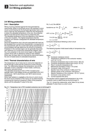
Operating characteristics and performance
2-2 Breaking performance
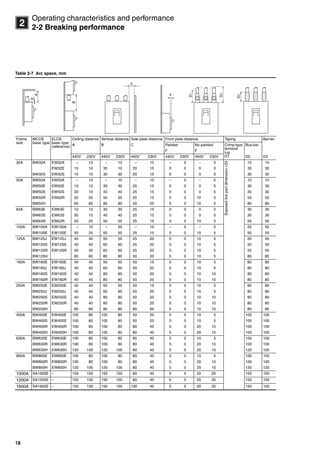
2-2-2 Breaking characteristics
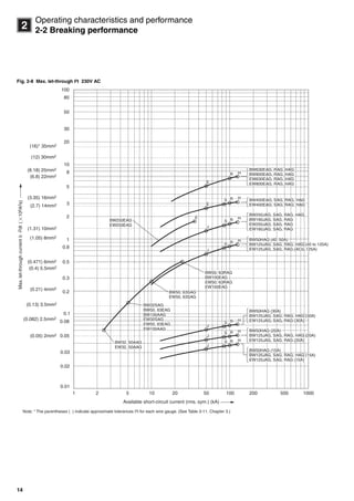
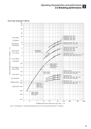
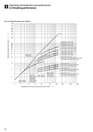
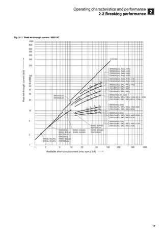
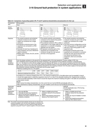
(1) Breaking performance
The characteristics that define MCCB breaking performance
are the rated short-circuit breaking capacity, peak let-through
current, and maximum let-through I2
t. The rated short-circuit
breaking capacity is defined by the rated ultimate short-circuit
breaking capacity (Icu), and the rated service short-circuit
breaking capacity (Ics).
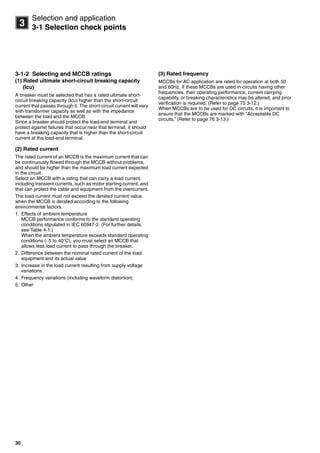
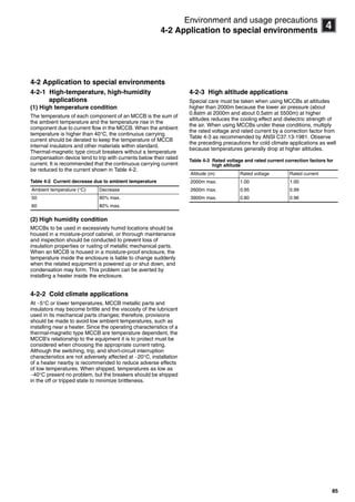
(2) Rated short-circuit breaking capacity
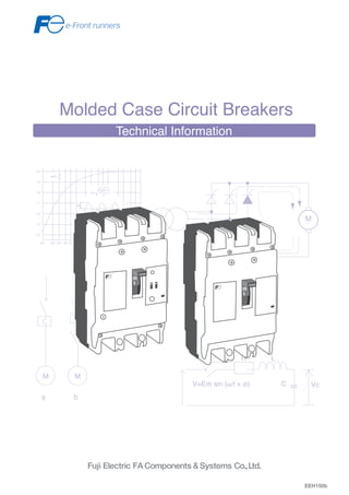
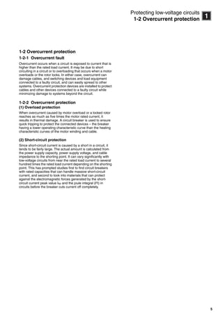
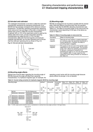
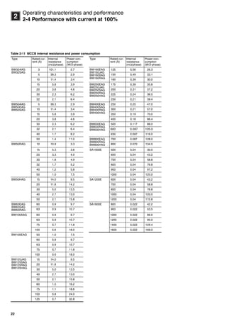
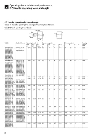
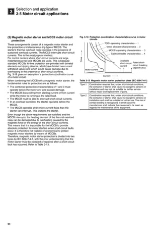
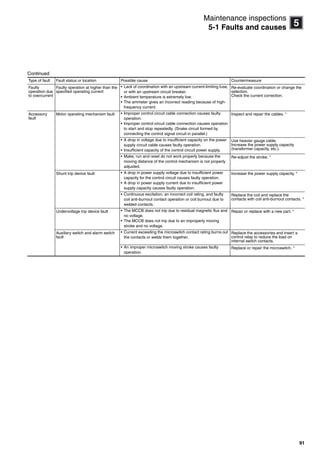
Fig. 2-6 is a typical oscillogram of a short-circuit current. In the
figure, t=0 denotes the time the short-circuit fault occurred. The
rated load current was flowing at the supply voltage before the
short-circuit fault occurred. The current by several factors of ten
flows after the occurrence of the short circuit. Because the load
current immediately after the short-circuit fault contains a DC
component, the current flow is asymmetrical with respect to the
zero-current line, with the DC component being attenuated
rapidly. The curve C-C’ represents the DC component of the
asymmetrical short-circuit current, and is indicates the current
that would flow if a short circuit occurred. This current is called
the available short-circuit current.
Fig. 2-6 Short-circuit current oscillogram
The rated breaking current of an MCCB is represented as
X/ , the effective value of the AC component 1/2 cycle after
the occurrence of the short-circuit fault. For a three-phase
circuit, the rated breaking current is represented the average of
the three phases.
For DC circuits, the maximum available short-circuit current is
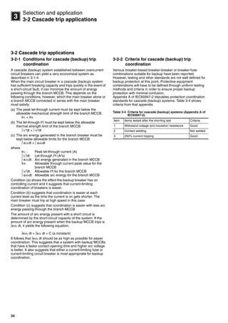
used.
(3) Operating duty
Under conditions where the displayed rated breaking capacity
is specified, breakers will break properly at an operating duty of
"O" -t- "CO" for Icu and "O" -t- "CO" -t- "CO" for Ics (where t is
three minutes or the time it takes to reset the breaker,
whichever is longer). All this is done at the rated voltage and
frequency. After the breaker trips, however, the rated current
may or may not flow, but the breaking capacity, durability, let-
through current and overload switching capacity will be
diminished. Therefore, replace the breaker with a spare as
quickly as possible. If current must be supplied with the same
breaker, conduct a maintenance inspection that looks closely
at the operating conditions prior to the breaker tripping, the
amount of short-circuit current, as well as future operating
conditions. Special attention must be paid to temperature rise
as well.
iS=iAC+iDC=Im [sin (ωt+ø−ϕ)−e L
Rt
−
sin (ø−ϕ)]
ø: Making phase angle
cosϕ: Short-circuit power factor
The value of the above equation reaches
its maximum when (ø−ϕ) = ± .
Im =
R2+(ωL)2√
Em
2
π
1/2 cycle
i
A
B
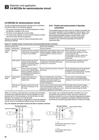
C
XY
P
iS
P'
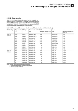
A'
C'
B'
t
0
i
iS: Short-circuit current
C-C': Intermediate line between the envelopes A-A' and B-B'
P-P': 1/2 cycle after occurrence of short-circuit fault
X: AC component of short-circuit current
Y: DC component of short-circuit current
2√
Circuit breakers_new.book Page 12 Wednesday, August 24, 2011 11:33 AM](https://image.slidesharecdn.com/mccbtechnicalinformation-141219010335-conversion-gate01/85/Molded-Case-Circuit-Breakers-Technical-Information-13-320.jpg)
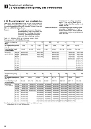
![38
3
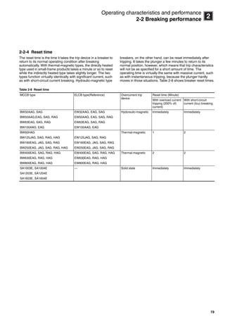
Selection and application
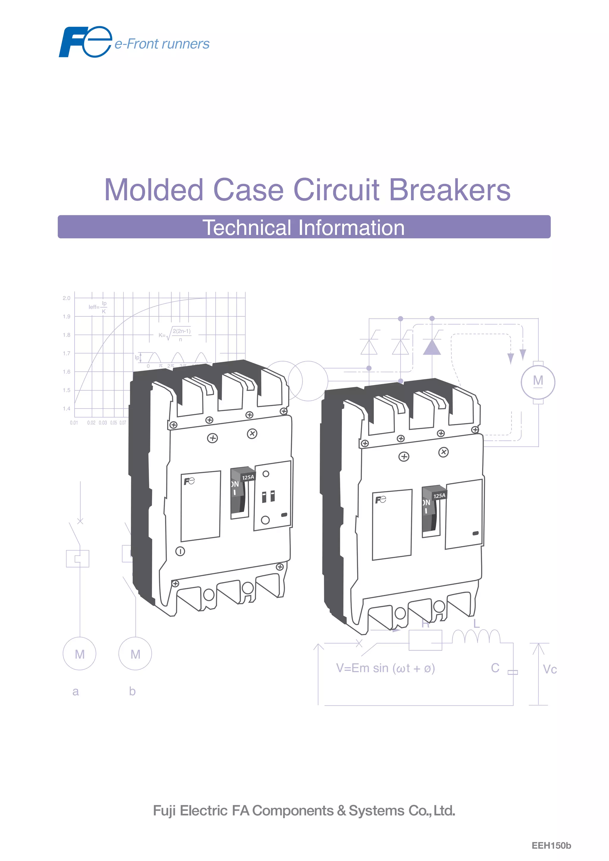
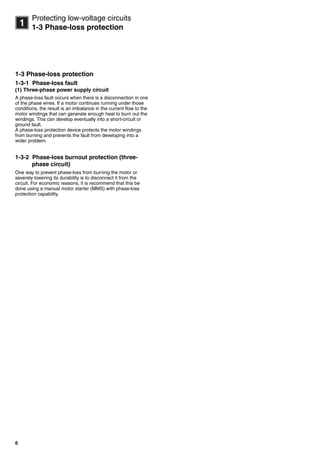
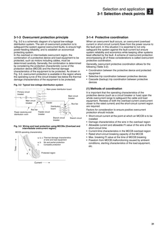
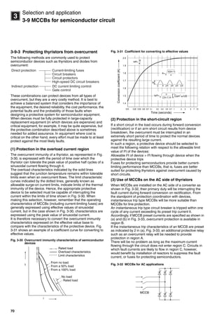
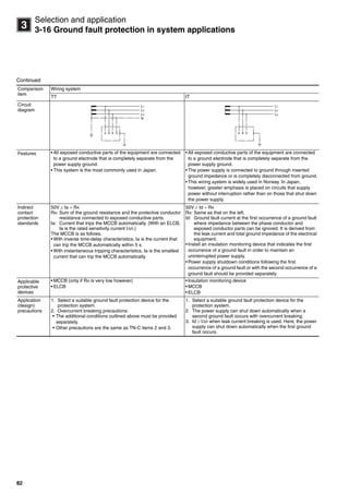
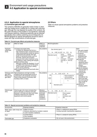
3-3 Selective trip applications
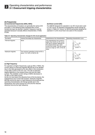
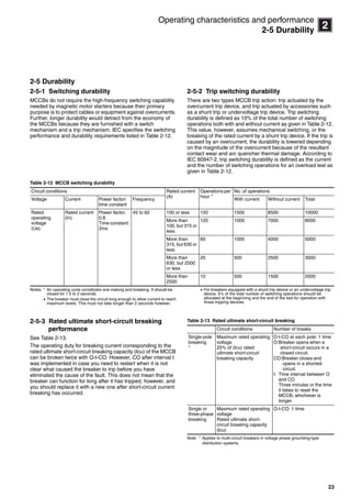
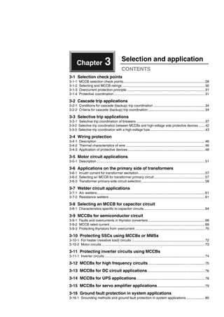
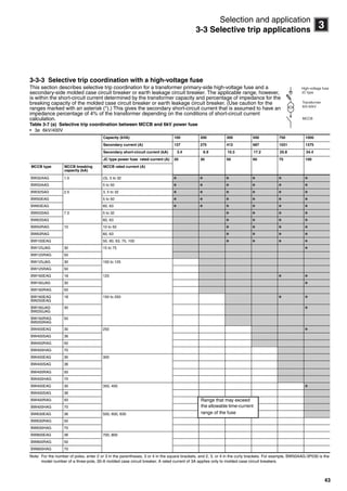
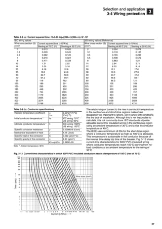
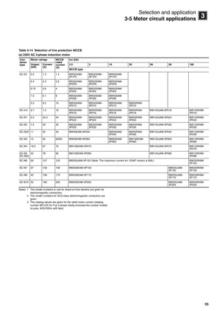
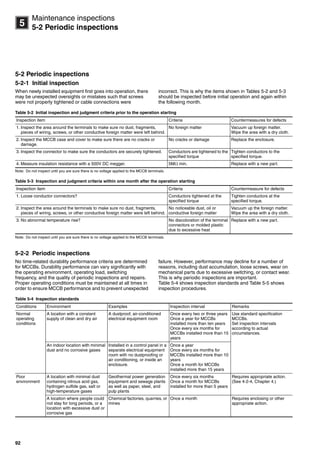
Table 3-6 (a) Selective trip coordination
Selective trip current: 230V AC
Note: The main circuit breakers are solid-state trip type MCCBs and ELCBs.
Contact FUJI for further information
Maincircuit
breaker
Type SA225E SA400E H400E SA600E H603E
Protective characteristics Ternary trip-element (long-time delay, short-time delay, instantaneous)
In (A) 125–225 200–400 200–400 300–600 300–600
Icu (kA) (sym) 85 85 100 85 100
Branchcircuitbreaker
MCCB ELCB (reference) Icu (kA) Icu (kA) For selective trip coordination
BW32AAG
BW50AAG
EW32AAG
EW50AAG
2.5 2.4 2.5 2.5 2.5 2.5
EW32EAG 2.5 2.4 2.5 2.5 2.5 2.5
BW50EAG
BW63EAG
EW50EAG
EW63EAG
5 2.4 3.8 3.8 5.0 5.0
BW100AAG EW100AAG 5 2.4 3.8 3.8 5.0 5.0
BW100EAG EW100EAG 25 2.4 3.8 3.8 6.0 6.0
BW160EAG
BW250EAG
EW160EAG
EW250EAG
36 – 3.8 3.8 6.0 6.0
BW400EAG EW400EAG 50 – – – 6.0 6.0
BW630EAG EW630EAG 50 – – – – –
BW800EAG EW800EAG 50 – – – – –
BW32SAG EW32SAG 5 2.4 3.8 3.8 5.0 5.0
BW50SAG
BW63SAG
EW50SAG
EW63SAG
10 2.4 3.8 3.8 6.0 6.0
BW125JAG EW125JAG 50 2.4 3.8 3.8 6.0 6.0
BW160JAG
BW250JAG
EW160JAG
EW250JAG
50 – 3.8 3.8 6.0 6.0
BW400SAG EW400SAG 85 – – – 6.0 6.0
BW50RAG
BW63RAG
EW50RAG
EW63RAG
25 2.4 3.8 3.8 6.0 6.0
BW125RAG EW125RAG 100 2.4 3.8 3.8 6.0 6.0
BW160RAG
BW250RAG
EW160RAG
EW250RAG
100 – 3.8 3.8 6.0 6.0
BW400RAG EW400RAG 100 – – – 6.0 6.0
BW630RAG EW630RAG 100 – – – – –
BW800RAG EW800RAG 100 – – – – –
BW50HAG EW50HAG 125 2.4 3.8 3.8 6.0 6.0
BW125HAG EW125HAG 125 2.4 3.8 3.8 6.0 6.0
BW250HAG EW250HAG 125 – 3.8 3.8 6.0 6.0
BW400HAG EW400HAG 125 – – – 6.0 6.0
BW630HAG EW630HAG 125 – – – – –
BW800HAG EW800HAG 125 – – – – –
: Tripping possible over entire range [unit: kA]
Circuit breakers_new.book Page 38 Wednesday, August 24, 2011 11:33 AM](https://image.slidesharecdn.com/mccbtechnicalinformation-141219010335-conversion-gate01/85/Molded-Case-Circuit-Breakers-Technical-Information-39-320.jpg)
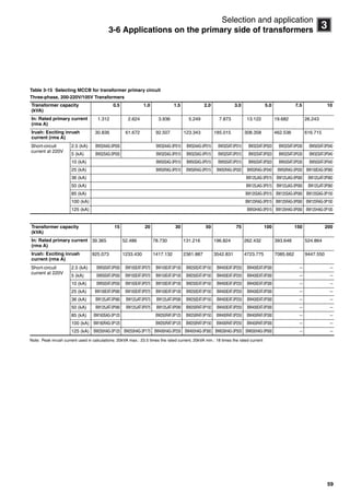
![39
3
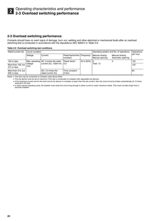
Selection and application
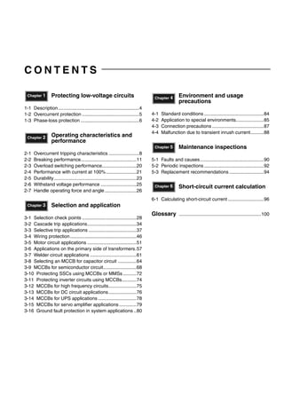
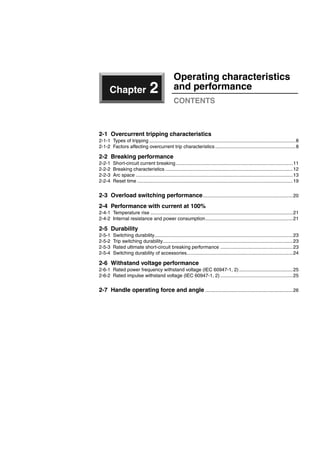
3-3 Selective trip applications
Selective trip current: 230V AC (Continued)
Note: The main circuit breakers are solid-state trip type MCCBs and ELCBs.
Contact FUJI for further information
Maincircuit
breaker
Type SA800E H800E SA1200E SA1600E SA2000E SA2500E
Protective characteristics Ternary trip-element (long-time delay, short-time delay, instantaneous)
In (A) 400–800 400–800 600–1200 800–1600 1000–2000 1200–2500
Icu (kA) (sym) 85 100 100 130 130 130
Branchcircuitbreaker
MCCB ELCB (reference) Icu (kA) Icu (kA) For selective trip coordination
BW32AAG
BW50AAG
EW32AAG
EW50AAG
2.5 2.5 2.5 2.5 2.5 2.5 2.5
EW32EAG 2.5 2.5 2.5 2.5 2.5 2.5 2.5
BW50EAG
BW63EAG
EW50EAG
EW63EAG
5 5.0 5.0 5.0 5.0 5.0 5.0
BW100AAG EW100AAG 5 5.0 5.0 5.0 5.0 5.0 5.0
BW100EAG EW100EAG 25 7.7 7.7 12.0 15.4 19.2 24.0
BW160EAG
BW250EAG
EW160EAG
EW250EAG
36 7.7 7.7 12.0 15.4 19.2 24.0
BW400EAG EW400EAG 50 7.7 7.7 12.0 15.4 19.2 24.0
BW630EAG EW630EAG 50 7.7 7.7 12.0 15.4 19.2 24.0
BW800EAG EW800EAG 50 – – 12.0 15.4 19.2 24.0
BW32SAG EW32SAG 5 5.0 5.0 5.0 5.0 5.0 5.0
BW50SAG
BW63SAG
EW50SAG
EW63SAG
10 7.7 7.7 10.0 10.0 110.0 10.0
BW125JAG EW125JAG 50 7.7 7.7 12.0 15.4 19.2 24.0
BW160JAG
BW250JAG
EW160JAG
EW250JAG
50 7.7 7.7 12.0 15.4 19.2 24.0
BW400SAG EW400SAG 85 7.7 7.7 12.0 15.4 19.2 24.0
BW50RAG
BW63RAG
EW50RAG
EW63RAG
25 7.7 7.7 12.0 15.4 19.2 24.0
BW125RAG EW125RAG 100 7.7 7.7 12.0 15.4 19.2 24.0
BW160RAG
BW250RAG
EW160RAG
EW250RAG
100 7.7 7.7 12.0 15.4 19.2 24.0
BW400RAG EW400RAG 100 7.7 7.7 12.0 15.4 19.2 24.0
BW630RAG EW630RAG 100 7.7 7.7 12.0 15.4 19.2 24.0
BW800RAG EW800RAG 100 – – 12.0 15.4 19.2 24.0
BW50HAG EW50HAG 125 7.7 7.7 12.0 15.4 19.2 24.0
BW125HAG EW125HAG 125 7.7 7.7 12.0 15.4 19.2 24.0
BW250HAG EW250HAG 125 7.7 7.7 12.0 15.4 19.2 24.0
BW400HAG EW400HAG 125 7.7 7.7 12.0 15.4 19.2 24.0
BW630HAG EW630HAG 125 7.7 7.7 12.0 15.4 19.2 24.0
BW800HAG EW800HAG 125 – – 12.0 15.4 19.2 24.0
: Tripping possible over entire range [unit: kA]
Circuit breakers_new.book Page 39 Wednesday, August 24, 2011 11:33 AM](https://image.slidesharecdn.com/mccbtechnicalinformation-141219010335-conversion-gate01/85/Molded-Case-Circuit-Breakers-Technical-Information-40-320.jpg)
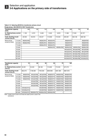
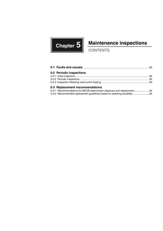
![40
3
Selection and application
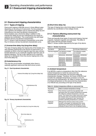
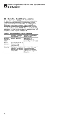
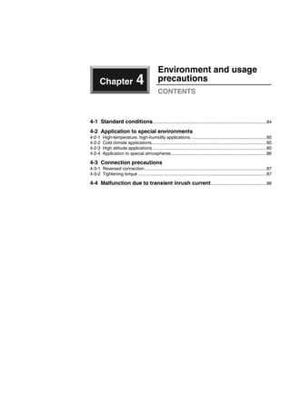
3-3 Selective trip applications
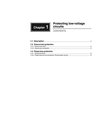
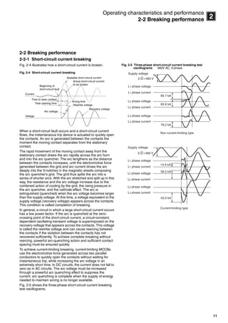
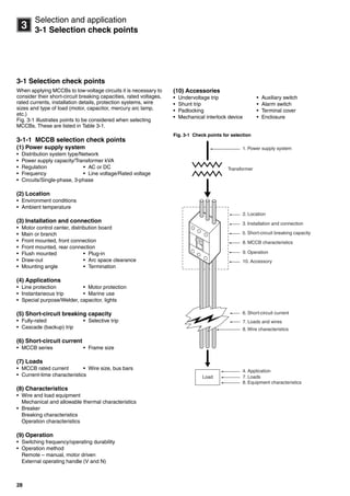
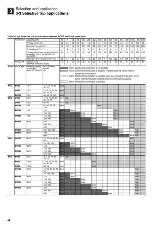
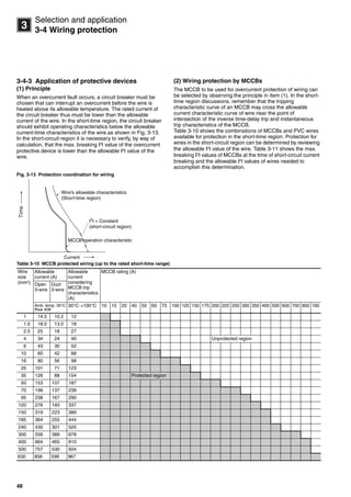
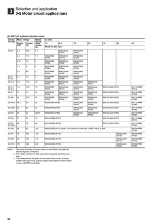
Table 3-6 (b) Selective trip coordination
Selective trip current: 400V AC
Note: The main circuit breakers are solid-state trip type MCCBs and ELCBs.
Contact FUJI for further information
Maincircuit
breaker
Type SA225E SA400E H400E SA600E H603E
Protective characteristics Ternary trip-element (long-time delay, short-time delay, instantaneous)
In (A) 125–225 200–400 200–400 300–600 300–600
Icu (kA) (sym) 50 50 65 50 65
Branchcircuitbreaker
MCCB ELCB (reference) Icu (kA) Icu (kA) For selective trip coordination
BW32AAG
BW50AAG
1.5 1.5 1.5 1.5 21.5 1.5
EW32EAG 1.5 1.5 1.5 1.5 1.5 1.5
BW50EAG
BW63EAG
EW50EAG
EW63EAG
2.5 2.4 2.5 2.5 2.5 2.5
BW100EAG EW100EAG 10 2.4 3.8 3.8 6.0 6.0
BW160EAG
BW250EAG
EW160EAG
EW250EAG
18 2.4 3.8 3.8 6.0 6.0
BW400EAG EW400EAG 30 – – – 6.0 6.0
BW630EAG EW630EAG 36 – – – – –
BW800EAG EW800EAG 36 – – – – –
BW32SAG EW32SAG 2.5 2.4 2.5 2.5 2.5 2.5
BW50SAG
BW63SAG
EW50SAG
EW63SAG
7.5 2.4 3.8 3.8 5.8 5.8
BW125JAG EW125JAG 30 2.4 3.8 3.8 5.8 5.8
BW160JAG
BW250JAG
EW160JAG
EW250JAG
30 2.4 3.8 3.8 5.8 5.8
BW400SAG EW400SAG 36 – – – 5.8 5.8
BW50RAG
BW63RAG
EW50RAG
EW63RAG
10 2.4 3.8 3.8 5.8 5.8
BW125RAG EW125RAG 50 2.4 3.8 3.8 5.8 5.8
BW160RAG
BW250RAG
EW160RAG
EW250RAG
50 2.4 3.8 3.8 5.8 5.8
BW400RAG EW400RAG 50 – – – 5.8 5.8
BW630RAG EW630RAG 50 – – – – –
BW800RAG EW800RAG 50 – – – – –
BW50HAG EW50HAG 65 2.4 3.8 3.8 5.8 5.8
BW125HAG EW125HAG 65 2.4 3.8 3.8 5.8 5.8
BW250HAG EW250HAG 65 2.4 3.8 3.8 5.8 5.8
BW400HAG EW400HAG 70 – – – 5.8 5.8
BW630HAG EW630HAG 70 – – – – –
BW800HAG EW800HAG 70 – – – – –
: Tripping possible over entire range [unit: kA]
Circuit breakers_new.book Page 40 Wednesday, August 24, 2011 11:33 AM](https://image.slidesharecdn.com/mccbtechnicalinformation-141219010335-conversion-gate01/85/Molded-Case-Circuit-Breakers-Technical-Information-41-320.jpg)
![41
3
Selection and application
3-3 Selective trip applications
Selective trip current: 400V AC (Continued)
Note: The main circuit breakers are solid-state trip type MCCBs and ELCBs.
Contact FUJI for further information
Maincircuit
breaker
Type SA800E H800E SA1200E SA1600E SA2000E SA2500E
Protective characteristics Ternary trip-element (long-time delay, short-time delay, instantaneous)
In (A) 400–800 400–800 600–1200 800–1600 1000–2000 1200–2500
Icu (kA) (sym) 50 65 65 85 85 85
Branchcircuitbreaker
MCCB ELCB (reference) Icu (kA) Icu (kA) For selective trip coordination
BW32AAG
BW50AAG
1.5 1.5 1.5 1.5 1.5 1.5 1.5
EW32EAG 1.5 1.5 1.5 1.5 1.5 1.5 1.5
BW50EAG
BW63EAG
EW50EAG
EW63EAG
2.5 2.5 2.5 2.5 2.5 2.5 2.5
BW100EAG EW100EAG 10 7.7 7.7 10.0 10.0 10.0 10.0
BW160EAG
BW250EAG
EW160EAG
EW250EAG
18 7.7 7.7 12.0 15.4 18.0 18.0
BW400EAG EW400EAG 30 7.7 7.7 12.0 15.4 19.2 24.0
BW630EAG EW630EAG 36 7.7 7.7 12.0 15.4 19.2 24.0
BW800EAG EW800EAG 36 – – 12.0 15.4 19.2 24.0
BW32SAG EW32SAG 2.5 2.5 2.5 2.5 2.5 2.5 2.5
BW50SAG
BW63SAG
EW50SAG
EW63SAG
7.5 7.5 7.5 7.5 7.5 7.5 7.5
BW125JAG EW125JAG 30 7.7 7.7 12.0 15.4 19.2 24.0
BW160JAG
BW250JAG
EW160JAG
EW250JAG
30 7.7 7.7 12.0 15.4 19.2 24.0
BW400SAG EW400SAG 36 7.7 7.7 12.0 15.4 19.2 24.0
BW50RAG
BW63RAG
EW50RAG
EW63RAG
10 7.7 7.7 10.0 10.0 10.0 10.0
BW125RAG EW125RAG 50 7.7 7.7 12.0 15.4 19.2 24.0
BW160RAG
BW250RAG
EW160RAG
EW250RAG
50 7.7 7.7 12.0 15.4 19.2 24.0
BW400RAG EW400RAG 50 7.7 7.7 12.0 15.4 19.2 24.0
BW630RAG EW630RAG 50 7.7 7.7 12.0 15.4 19.2 24.0
BW800RAG EW800RAG 50 – – 12.0 15.4 19.2 24.0
BW50HAG EW50HAG 65 7.7 7.7 10.0 10.0 19.2 24.0
BW125HAG EW125HAG 65 7.7 7.7 12.0 15.4 19.2 24.0
BW250HAG EW250HAG 65 7.7 7.7 12.0 15.4 19.2 24.0
BW400HAG EW400HAG 70 7.7 7.7 12.0 15.4 19.2 24.0
BW630HAG EW630HAG 70 7.7 7.7 12.0 15.4 19.2 24.0
BW800HAG EW800HAG 70 – – 12.0 15.4 19.2 24.0
: Tripping possible over entire range [unit: kA]
Circuit breakers_new.book Page 41 Wednesday, August 24, 2011 11:33 AM](https://image.slidesharecdn.com/mccbtechnicalinformation-141219010335-conversion-gate01/85/Molded-Case-Circuit-Breakers-Technical-Information-42-320.jpg)
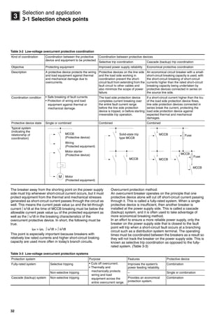
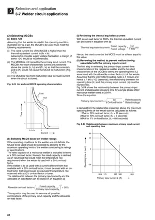
![61
3
Selection and application
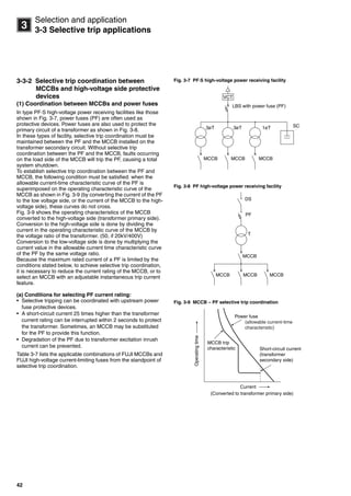
3-7 Welder circuit applications
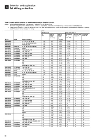
3-7 Welder circuit applications
3-7-1 Arc welders
MCCBs installed in arc welder circuits should not inadvertently
trip due to the massive inrush current generated at ignition.
Inadvertent tripping often occurs when inrush current instantly
trips the overcurrent tripping element in the MCCB. Since the
transient inrush current in arc welders is 8 to 9 times the
primary current, an MCCB that can handle at least ten times
the rated primary current without tripping should be selected
for this kind of application.
3-7-2 Resistance welders
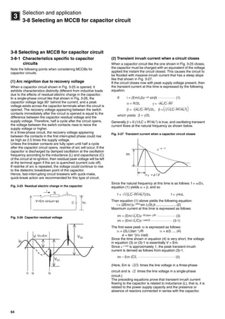
(1) Characteristics specific to resistance welder
circuits
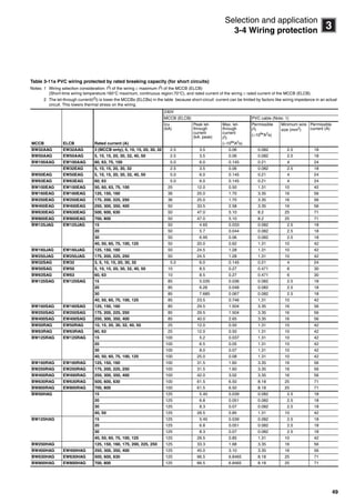
Resistance welders are characterized by intermittent operation
with short switching intervals and also by switching in the
primary circuit of the welder transformer. Consequently, the
following points must be considered when selecting an MCCB:
(a) Thermal equivalent current
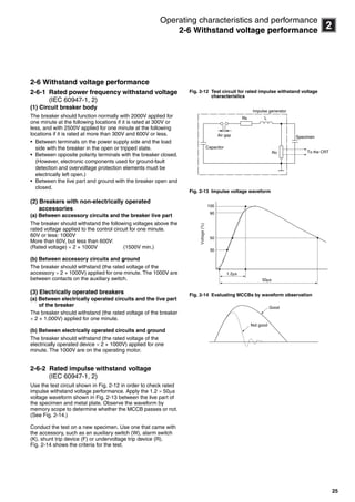
The current that flows through the welding circuit is repetitive
with short periods as shown in Fig. 3-22. Since the MCCB
operation or the temperature rise in the wire is determined by a
thermal equivalent current, the current flowing during
intermittent operation must be converted to a thermally
equivalent continuous current.
(i) Thermal equivalent current Ia during period t (seconds)
Assuming that the current flowing time for resistance welding
by the current IL [A] is tL (seconds) per point, and that
resistance welding is conducted at one point per t (seconds),
then the on-load factor of the welder can be stated in an
equation as:
In this current flowing state, the amount of heat W generated
by the total circuit resistance R per t (seconds) can be
represented as
W = (IL)2·R·tL (joule)
If this value is taken as the average amount of heat generated
per t (seconds), then the equation derives as follows.
This means that the generated heat is equal to the amount of
heat that would be generated upon continuous flow of the
current . Hence, the thermal equivalent current Ia at
period t (seconds) can be stated as
(ii) Thermal equivalent current IB at period T (seconds)
In Fig. 3-22, the thermal equivalent current IB at period TL
(seconds) is similar to that at period t (seconds). At period T
(seconds), however, the thermal equivalent current IB can be
represented as:
Fig. 3-22 Typical intermittent operation
(b) Transient inrush current caused by switching
transformer primary circuit
For resistance welders load switching is carried out in the
primary circuit of the welder transformer. Consequently, a high
transient inrush current may flow when the circuit is closed, as
mentioned under “Selecting an MCCB for transformer primary
circuit” (See page 57).
Whether or not inrush current flows depends on the type of
switching control system used in resistance welders because
inrush current is generated by the closed circuit phase or by
residual magnetic flux in the transformer core. Switching is
controlled using synchronous, semi-synchronous, or
asynchronous systems.
Inrush current does not occur with synchronous control
systems because they can control the current flow start phase
and they can reverse the start polarity by the time the current
flow ends.
Semi-synchronous control systems can control the current flow
start phase, but cannot necessarily reverse the start polarity by
the time the current flow ends. Inrush current may therefore
occur here due to biased excitation of the core, but this is
generally not a problem because these systems can
adequately control the making phase.
Most semi-synchronous control systems today use thyristors
for main current switching. With the anti-surge current
capability of the thyristor as well, these systems take the half
cycle at the start of the closed circuit phase and insert it just
past the voltage phase /2 to prevent inrush current.
Asynchronous control systems use a magnetic contactor for
main current switching. Here, the closed circuit phase
generates massive inrush current as high as 20 times the
steady state current. This is why newer welders now use either
synchronous or semi-synchronous control systems.
Period
Current flowing time
α = =
t
tL
t
W
√
= (IL)2 • R•
t
tL
= (IL)2• R• α
= R(IL α)2
√IL α (A)
√Ia = IL α (A)
√IB = IL β (A) where, β = n• tL/T
n = TL/t
tL
IL
t
TL
T
Circuit breakers_new.book Page 61 Wednesday, August 24, 2011 11:33 AM](https://image.slidesharecdn.com/mccbtechnicalinformation-141219010335-conversion-gate01/85/Molded-Case-Circuit-Breakers-Technical-Information-62-320.jpg)
![63
3
Selection and application
3-7 Welder circuit applications
However, since the standard maximum input is prescribed for a
resistance welder, even if the secondary circuit is fully shorted,
the maximum short-circuit current is some 30% higher than the
rated welding current (secondary current corresponding to the
standard maximum input) at most. Consequently, allowance
would be needed only for a value about 30% higher than the
current corresponding to the standard maximum input.
Assuming a standard maximum input of 55kVA at 230V AC
single-phase, IL (max) is calculated as
This result requires that the tLIL curve shown in Fig. 3-24 be
positioned below the hot-start characteristic curve of the
MCCB in the range IL 310 (A). A general guideline for filling
this requirement is to set the rated current of the MCCB at least
1.5 times higher than the thermal equivalent current calculated
in (i).
(iii)Method to keep the MCCB free from malfunctioning
caused by the inrush current when the circuit is closed.
With welders that use thyristors to permit closed circuit phase
control, such as those operating in synchronous or semi-
synchronous mode, the inrush current associated with the
biased excitation of the transformer core would not be much of
a problem. Rather, only the inrush current associated with the
superposed DC component needs to be considered.
Specifically, a choice should be made of an MCCB having its
instantaneous tripping current at least two times the IL (max)
calculated in (ii).
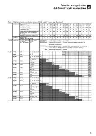
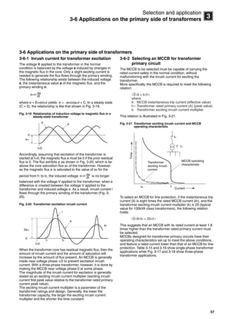
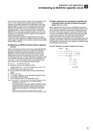
Table 3-19 lists typical MCCBs that are selected to work with
resistance welders that operate in synchronous or semi-
synchronous mode, pursuant to the requirements given in (i) to
(iii) above. Since, generally, the standard maximum input of a
welder is some three times its rated capacity, and the
instantaneous tripping current of an MCCB is eight times its
rated current or higher, the following equation may be used to
select an MCCB to work with welders that operate in
synchronous or semi-synchronous mode:
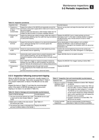
Table 3-19 Spot welder circuit motor breaker selection
Note: This table applies to models that can use a thyristor to perform phase
control at startup for a synchronous or semi-synchronous system.
× 1.3 ≈ 310 [A]55000
230
IL (max) =
IN > 1.1 ×
Rated capacity
Rated voltage
Assumption:
Max. input capacity
Rated capacity
≤ 3
IN = MCCB rated current
Resistance welder Single-phase, 200V
Circuit short-circuit capacity (kA) (The
short-circuit current at the service entrance
must be less than the following values.)
Rated
capacity
example
(kVA)
Maximu
m input
example
(kVA)
5 25 36 50 100
15 35 BW100
AAG-
2P100
BW100
EAG-
2P100
BW125JAG-
2P100
30 65 BW125JAG-2P125 BW125
RAG-
2P125
55 140 BW250EAG-2P225 BW250RAG-
2P225
Resistance welder Single-phase, 400V
Circuit short-circuit capacity (kA)
(The short-circuit current at the
service entrance must be less
than the following values.)
Rated
capacity
example
(kVA)
Maximu
m input
example
(kVA)
10 18 30 50
15 35 BW50
RAG-
2P050
BW125JAG-
2P050
BW125
RAG-
2P050
30 65 BW100
EAG-
2P100
BW125JAG-
2P100
BW125
RAG-
2P100
55 140 BW125JAG-2P125 BW125
RAG-
2P125
Circuit breakers_new.book Page 63 Wednesday, August 24, 2011 11:33 AM](https://image.slidesharecdn.com/mccbtechnicalinformation-141219010335-conversion-gate01/85/Molded-Case-Circuit-Breakers-Technical-Information-64-320.jpg)

![76
3
Selection and application
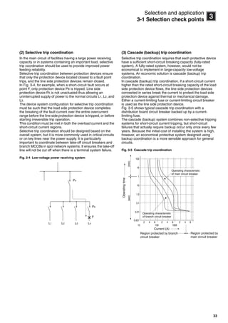
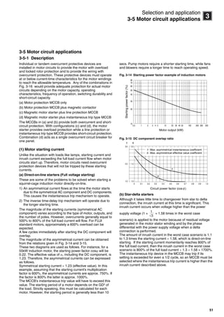
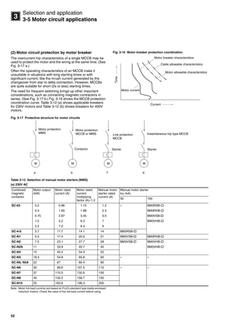
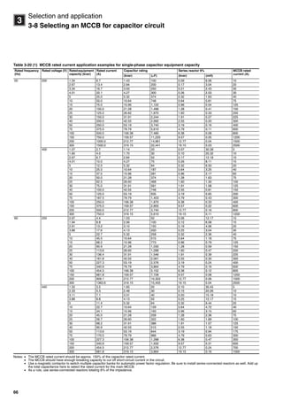
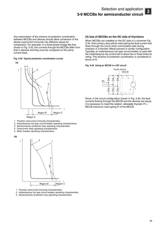
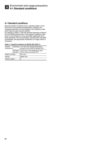
3-13 MCCBs for DC circuit applications
3-13 MCCBs for DC circuit applications
The operating characteristics of an MCCB adjusted for AC
specifications will not be the same in a DC application, so use
an MCCB adjusted specifically for DC specifications in those
applications. (See Table 2-5 section 2-1, Chapter 2.)
Breaking is harder with DC current than with AC current at high
voltages because there is no zero crossing point with DC
current. Breaking is difficult using AC if the voltage is high
because there is no zero point for DC. In normal use, the circuit
voltage is 250V max., but application is possible up to 400V DC
for a three-pole series connection and up to 600V DC for four
poles, as shown in the figure. Special-order products are DC-
only. Specify if required.
Table 3-27 MCCBs for 250V DC circuit applications
Notes: The time constant is 10 s max.
The instantaneous DC tripping current for AC/DC models is approximately 140% max. of the AC rating. Models with the same instantaneous tripping current
as the operating characteristics curve given in a catalog or other documentation can be produced if “C2” is specified at the end of the model number. (DC-only
models) Example: BW125JAG-2P100 C2
Tripping device MCCB type DC load application Rated insulation
voltage (V)
Rated breaking
capacity [kA]
Icu/Ics at 250 VDC
Hydraulic-magnetic BW32SAG Specially designed MCCB is required
(standard type MCCB cannot be used).
(Specified by “C2” at the end of the
model number when ordering.)
250V DC 2.5/2 Note: There is no polarity.
BW50EAG 2.5/2
BW63EAG 2.5/2
BW50SAG 5/3
BW63SAG 5/3
BW50RAG 5/3
BW63RAG 5/3
BW100EAG 5/3
Thermal-magnetic BW50HAG-3P Standard type MCCB can be used. 250V DC 40/20
BW125JAG 15/8
BW125RAG 40/20
BW125HAG-3P 40/20
BW250EAG 10/5
BW250JAG 20/10
BW250RAG 30/15
BW250HAG-3P 30/15
BW400EAG 20/10
BW400SAG 20/10
BW400RAG 40/20
BW400HAG 40/20
BW630EAG-3P 20/10
BW630RAG-3P 40/20
BW630HAG-3P 40/20
BW800EAG-3P 20/10
BW800RAG-3P 40/20
BW800HAG-3P 40/20
Instantaneous trip
type
BW32SAQ Specially designed MCCB is required
(standard type MCCB cannot be used).
(Specified by “C2” at the end of the
model number when ordering.)
250V DC 2.5/2
BW50SAQ 5/3
BW63EAQ 2.5/2
BW63SAQ 5/3
BW125JAQ 15/8
BW125RAQ 40/20
BW250JAQ 20/10
BW250RAQ 30/15
BW400RAQ 40/20
BW400HAQ 40/20
BW630RAQ-3P 40/20
BW630HAQ-3P 40/20
BW800RAQ-3P 40/20
BW800HAQ-3P 40/20
Disconnect switch BW32SAS Standard type MCCB can be used. 250V DC
BW50SAS
BW63SAS
BW100EAS
BW125JAS
BW125RAS
BW250EAS
BW250RAS
BW400EAS
BW400RAS
BW630EAS
BW630RAS
BW800EAS
2-pole model
Power supply (250V)
Load
3-pole model
Power supply (250V)
Load
Circuit breakers_new.book Page 76 Wednesday, August 24, 2011 11:33 AM](https://image.slidesharecdn.com/mccbtechnicalinformation-141219010335-conversion-gate01/85/Molded-Case-Circuit-Breakers-Technical-Information-77-320.jpg)
![77
3
Selection and application
3-13 MCCBs for DC circuit applications
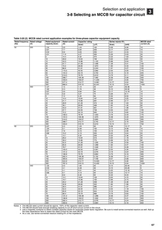
Table 3-28(1) MCCBs for 400 and 500V DC applications
Table 3-28(2) MCCBs for 600V DC applications
Notes: The instantaneous DC tripping current for AC/DC models is approximately 140% max. of the AC rating. Models with the same instantaneous tripping current
as the operating characteristics curve given in a catalog or other documentation can be produced if “C5” or “C6” is specified at the end of the model number.
(DC-only models)
Only 250V DC models are given for standard products. If 500V DC or 600V DC is required, specify “C5” (for 500V DC) and “C6” (for 600V DC) at the end of
the model number. (DC-only models)
Tripping device MCCB type DC load application Rated insulation
voltage (V)
Rated breaking
capacity [kA]
Icu/Ics at 250 VDC
Hydraulic-
magnetic
BW32SAG-3P Specially designed MCCB is
required (standard type MCCB
cannot be used). (Specified by
“C4” at the end of the model
number when ordering.)
400V DC 2.5
BW50SAG-3P 5
BW63SAG-3P 5
BW100EAG-3P 5
Thermal-
magnetic
BW125JAG-3P Specially designed MCCB is
required (standard type MCCB
cannot be used). (Specified by
“C5” at the end of the model
number when ordering.)
500V DC 10
BW125RAG-3P 20
BW250JAG-3P 10
BW250RAG-3P 20
BW400EAG-3P Standard type MCCB can be
used.
20
BW400SAG-3P 20
BW400RAG-3P 40
BW400HAG-3P 40
BW630EAG-3P 20
BW630RAG-3P 40
BW630HAG-3P 40
BW800EAG-3P 20
BW800RAG-3P 40
BW800HAG-3P 40
Disconnect
switch
BW32SAS-3P32 Specially designed MCCB is
required (standard type MCCB
cannot be used). (Specified by
“C4” at the end of the model
number when ordering.)
400V DC
BW50SAS-3P50
BW63SAS-3P63
BW100EAS-3P100
BW125JAS-3P125 Specially designed MCCB is
required (standard type MCCB
cannot be used). (Specified by
“C5” at the end of the model
number when ordering.)
500V DC
BW125RAS-3P125
BW250EAS-3P250
BW250RAS-3P250
BW400EAS-3P400 Standard type MCCB can be
used.BW400RAS-3P400
BW630EAS-3P630
BW630RAS-3P630
BW800EAS-3P800
BW800RAS-3P800
3-pole model
Power supply (251 to 500V DC)
Load
Tripping
method
Model number Application to DC circuit Rated insulation
voltage (V)
Rated breaking
capacity [kA]
Icu/Ics at 250 VDC
Thermal-
magnetic
BW125RAG-4P Can be used with special-order
products. Specified by “C6” at the
end of the model number when
ordering.
600V DC 25
BW250JAG-4P 25
BW250RAG-4P 40
BW400RAG-4P Can be used with standard
products. (See notes 1 and 2.)
40
BW400HAG-4P 40
BW630RAG-4P 40
BW630HAG-4P 40
BW800RAG-4P 40
BW800HAG-4P 40
Disconnect
switch
BW125RAS-4P125 Can be used with special-order
products.
Specified by “C6” at the end of
the model number when
ordering.
BW250RAS-4P250
BW400RAS-4P400 Can be used with standard
products. (See note 2.)BW630RAS-4P630
BW800RAS-4P800
4-pole model
Power supply (251 to 600V DC)
Load
Circuit breakers_new.book Page 77 Wednesday, August 24, 2011 11:33 AM](https://image.slidesharecdn.com/mccbtechnicalinformation-141219010335-conversion-gate01/85/Molded-Case-Circuit-Breakers-Technical-Information-78-320.jpg)

![79
3
Selection and application
3-15 MCCBs for servo amplifier applications
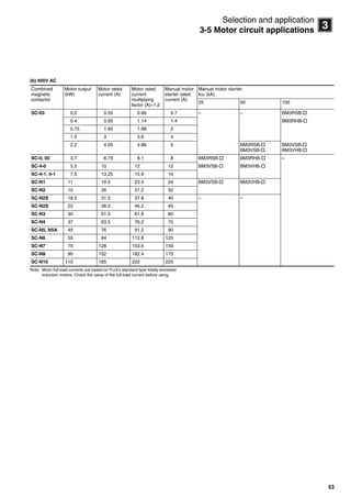
3-15 MCCBs for servo amplifier applications
Install an MCCB on the primary side of the servo amplifier for
power supply switching and to prevent damage caused by
short-circuit current.
Table 3-29 lists the types that are available for servo amplifier
applications. Servo amplifiers are equipped with overcurrent
(output side) and other protective functions.
Table 3-29 MCCBs for servo amplifiers (FALDIC- and - series)
Input power
supply
Output
[kW]
FALDIC- and - series FALDIC- series MCCB type ELCB (reference)
type
Three-phase
230V
0.05 Standard series RYS500S3- Standard series
100V series
RYB500S3-VBC BW32AAG-3P003 EW32SAG-3P003
0.1 RYS101S3- RYB101S3-VBC
0.2 RYS201S3- RYB201S3-VBC BW32AAG-3P005 EW32EAG-3P005
0.4 RYS401S3- RYB401S3-VBC BW32AAG-3P010 EW32EAG-3P010
0.75 RYS751S3- RYB751S3-VBC BW50EAG-3P015 EW50EAG-3P015
1 RYS102S3- BW50EAG-3P015 EW50EAG-3P015
1.5 RYS152S3-
2 RYS202S3- BW50EAG-3P030 EW50EAG-3P030
3 RYS302S3- BW50EAG-3P040 EW50EAG-3P040
4 RYS402S3- BW50EAG-3P050 EW50EAG-3P050
5 RYS502S3-
0.5 Low-base speed
series
RYS501A3- BW50EAG-3P015 EW50EAG-3P015
1.5 RYS152A3-
2.5 RYS252A3- BW50EAG-3P040 EW50EAG-3P040
2.9 Medium capacity
- series
RYS292M3- BW50EAG-3P040 EW50EAG-3P040
4 RYS402M3- BW50EAG-3P050 EW50EAG-3P050
5.5 RYS552M3-
7.5 RYS752M3- BW100EAG-3P075 EW100EAG-3P075
11 RYS113M3- BW100EAG-3P100 EW100EAG-3P100
15 RYS153M3- BW125JAG-3P125 EW125JAG-3P125
Circuit breakers_new.book Page 79 Wednesday, August 24, 2011 11:33 AM](https://image.slidesharecdn.com/mccbtechnicalinformation-141219010335-conversion-gate01/85/Molded-Case-Circuit-Breakers-Technical-Information-80-320.jpg)
![87
14
Environment and usage precautions
4-3 Connection precautions
4-3 Connection precautions
4-3-1 Reversed connection
The power supply side and the load side are indicated on the
following products. The breaking capacity for power supply
reverse connection is different than that for regular connection.
Table 4-8 Breaking capacity for MCCB connected in reverse
Note: Reverse connection is possible with standard products of 125AF or higher.
4-3-2 Tightening torque
Conductor connections should be tightened to the specified
torque because loose connections may cause overheating or
malfunctioning while overtightening may damage the screw or
the molded plastic. Always use the appropriate screwdriver for
the screw head.
Soldering must not be done when using a box-type terminal
connection.
Model number Reverse connection breaking capacity
[kA] (JIS C 8201-2-1 Ann. 2)
200V 400V
BW32AAG 2.5
BW32SAG 5 2.5
BW50AAG 2.5
BW50EAG 5 2.5
BW50SAG 10 2.5
BW50RAG 15 2.5
BW63EAG 5 2.5
BW63SAG 10 2.5
BW63RAG 15 2.5
BW100AAG 5
BW100EAG 15 2.5
ON
OFF
Regular connection
ON
OFF
Reverse connection
Circuit breakers_new.book Page 87 Wednesday, August 24, 2011 11:33 AM](https://image.slidesharecdn.com/mccbtechnicalinformation-141219010335-conversion-gate01/85/Molded-Case-Circuit-Breakers-Technical-Information-88-320.jpg)

![97
6
Short-circuit current calculation
6-1 Calculating short-circuit current
• Step 3 Creating an impedance map
Create an impedance map using the impedance calculated in
step 2. Sources of short-circuit current like a power supply and
motor constitute the same electric potential in an impedance
map. Connect these sources together with an infinite busbar as
shown in Fig. 6-2 and be very careful connecting impedance in
series or in parallel between the busbar and fault point F when
creating the impedance map.
• Step 4 Unifying impedance
Take the impedance map shown in Fig. 6-2 and use series-
parallel calculations to unify all impedance as shown in
Fig. 6-3.
• Step 5 Calculating effective values for
symmetrical short-circuit current
IF = (3ø) = IF (rms) sym (3ø)
Fig. 6-2
Fig. 6-3
√
%Z = %R + j%X
%Z = (%R)2 + (%X)2
3VB%Z√
PB × 103
= × 100
%Z
100= IB × [A]
Infinite busbar
j%X1
%RT
j%XT
j%X5
%R5
j%X5
j%X2
%R4
j%X4
F
j%Xn
j%X3
%Rn
j%Xn
Infinite busbar
j%X
%R
F
Circuit breakers_new.book Page 97 Wednesday, August 24, 2011 11:33 AM](https://image.slidesharecdn.com/mccbtechnicalinformation-141219010335-conversion-gate01/85/Molded-Case-Circuit-Breakers-Technical-Information-98-320.jpg)
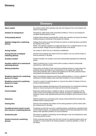
![102
Glossary
Glossary
Inverse time-delay overcurrent
relay or release (trip device)
An overcurrent relay or release (trip device) which operates after a time-delay
inversely dependent upon the value of the overcurrent.
NOTE: Such a relay or release (trip device) may be designed so that the time-delay
approaches a definite minimum value for high values of overcurrent.
Isolating distance (of a pole of a
mechanical switching device)
Clearance between open contacts meeting the safety requirements specified for
disconnectors.
I2
t characteristic of a circuit
breaker
Information (usually a curve) giving the maximum values of I2
t related to break time
as a function of prospective current (r.m.s. symmetrical for AC) up to the maximum
prospective current corresponding to the rated short-current breaking capacity and
associated voltage.
Joule integral (I2
t) Integral of the square of the current over a given time interval:
I2
t = i 2
dt
Let-through current ( = Cut-off
current)
See "Cut-off current."
Live part Conductor or conductive part intended to be energized in normal use, including a
neutral conductor but, by convention, not a PEN conductor.
NOTE: This term does not necessarily imply a risk of electric shock.
Magnetic overload relay or
release (trip device)
Overload relay or release (trip device) depending for its operation on the force
exerted by the current in the main circuit exciting the coil of an electromagnet.
NOTE: Such a relay or release (trip device) usually has an inverse time-delay/current
characteristic.
Main circuit (of a switching
device)
All the conductive parts of a switching device included in the circuit which it is
designed to close or open.
Main contact Contact included in the main circuit of a mechanical switching device, intended to
carry, in the closed position, the current of the main circuit.
Make time Interval of time between the initiation of the closing operation and the instant when
the current begins to flow in the main circuit.
Maximum prospective peak
current (of an AC circuit)
Prospective peak current when initiation of the current takes place at the instant
which leads to the highest possible value.
NOTE: For a multipole device in a polyphase circuit, the maximum prospective peak
current refers to one pole only.
Molded case circuit breaker A circuit breaker having a supporting housing of molded insulating material forming
an integral part of the circuit breaker.
Neutral conductor (symbol N) Conductor connected to the neutral point of a system and capable of contributing to
the transmission of electrical energy.
NOTE: In some cases, the functions of the neutral conductor and the protective
conductor may be combined under specified conditions in one and the same
conductor referred to as the PEN conductor [Symbol PEN].
Opening time (of a mechanical
switching device)
Interval of time between the specified instant of initiation of the opening operation
and the instant when the arcing contacts have separated in all poles.
NOTE: The instant of initiation of the opening operation, i.e. the application of the
opening command (e.g. energizing the release), is given in the relevant product
standard.
Overcurrent Current exceeding the rated current.
Circuit breakers_new.book Page 102 Wednesday, August 24, 2011 11:33 AM](https://image.slidesharecdn.com/mccbtechnicalinformation-141219010335-conversion-gate01/85/Molded-Case-Circuit-Breakers-Technical-Information-103-320.jpg)


The document provides technical information on molded case circuit breakers (MCCBs) from Fuji Electric, emphasizing safe operating conditions and the necessary precautions for various applications, especially in environments that may affect human life or property. It details overcurrent and phase-loss protections, the performance characteristics of MCCBs, and specific applications such as motor circuits and short-circuit protections, while urging consultation with professionals for specific usage scenarios. Additionally, it includes guidelines for maintenance, disposal, and the importance of adhering to technical specifications for reliable and efficient circuit breaker operation.


![Breakers v. fuses[1]](https://cdn.slidesharecdn.com/ss_thumbnails/breakersv-140206124350-phpapp02-thumbnail.jpg?width=640&height=640&fit=bounds)


