Download to read offline
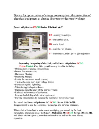
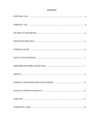
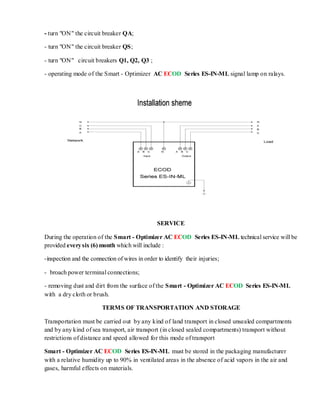


The Smart Optimizer ECOD series is designed for energy consumption optimization, voltage regulation, and protection of electrical equipment, offering features such as power factor correction and harmonic filtering. Installation requires adherence to safety protocols, and the device must be serviced every six months to ensure proper functioning. It has a warranty of 36 months, and its technical specifications include a wide input voltage range and high efficiency.