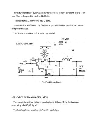
FRANKLIN OSCILLATOR
The local oscillator for, a balanced modulator generating single or double
sideband amplitude modulated wave is based on the Franklin oscillator, that was
so popular in the first half of this century.
The Franklin circuit used two vacuum tubes, this circuit uses two direct coupled
FET’s.
The Inductor Li is wound on a ceramic former, about 1/2 inch (12.5mm)
Diameter.
Ceramic coil former can be made from an old 1KW electric fire (heater)
element by nicking the element with a hacksaw, and breaking it on a hard surface.
Drilling holes in it will not help. The main tuning capacitor is a double bearing
type, value about 2Opf.
The trimmer cap is a good quality air spaced type. The 5Opf fixed cap (47pf
actually) is polystyrene.
The trimmer marked, 5p should be adjusted to the minimum value that gives
reliable operation, a 5mm ceramic trimmer, 3/20pf would be appropriate.
The VFO should be built in a well screened box.
The VFO output is about 700m Vpp, further amplification will be needed to
drive a high level diode, or mosfet mixer.
Here a digital VFO stabilizer is used, so good long term frequency stability will
not be too difficult to achieve.
The LO. AMP. Increases the VFO signal level to about +17 dBm (50 mW).
This uses a 2N2219A transistor.
The transformer is wound on a small ferrite ring (the same type as used for the
balanced modulator), 6 turns bifilar winding.
Twist two lengths of pvc insulated wire together, use two different colors T low
pass filter is designed to work at 11.5 MHz.
The inductor is 12 Turns on a T50-2 core.
If your rig has a different L.O. frequency, you will need to re-calculate the LPF
component values.
The 5R resistor is two 10 R resistors in parallel.
APPLICATION OF FRANKLIN OSCILLATOR:
The simple, two diode balanced modulator is still one of the best ways of
generating a DSB/SSB signal.
The local oscillator used here is Franklin oscillator.
You can use Silicon switching diodes, 1N914, 1N4148, Germanium point contact
diodes, 1N34, or Schottky (Hot Carrier) diodes.
Both transistors are BC548’s, for the reasons mentioned above.
The transformer is wound on a high permeability (ui = 850) ferrite core.
2K2 resistor at the output, supplies a few mA to a diode switch in my receiver.
This allows the same crystal filter to be used for transmit and receive.
If only transmitter is built, this resistor should be omitted.
The modules constructed so far will work on any band.
Decide what band you want to use, work out the local oscillator frequency,
allowing for the IF offset, then build a suitable oscillator / PLL / DDS.
An SSB transceiver requires the 80 Metre band.
The IF frequency here is 7.8MHz, the local oscillator frequency range required
is, 1 1.3 MHz to 11.6 MHz to cover from 3.5 to 3.8 Mhz.
This local Franklin oscillator can easily be modified to work on other
frequencies, if you are using a different IF.
Source :http://mediatoget.blogspot.in/2011/09/franklin-oscillator.html

Franklin oscillator

  • 1.
    FRANKLIN OSCILLATOR The localoscillator for, a balanced modulator generating single or double sideband amplitude modulated wave is based on the Franklin oscillator, that was so popular in the first half of this century. The Franklin circuit used two vacuum tubes, this circuit uses two direct coupled FET’s. The Inductor Li is wound on a ceramic former, about 1/2 inch (12.5mm) Diameter. Ceramic coil former can be made from an old 1KW electric fire (heater) element by nicking the element with a hacksaw, and breaking it on a hard surface. Drilling holes in it will not help. The main tuning capacitor is a double bearing type, value about 2Opf. The trimmer cap is a good quality air spaced type. The 5Opf fixed cap (47pf actually) is polystyrene. The trimmer marked, 5p should be adjusted to the minimum value that gives reliable operation, a 5mm ceramic trimmer, 3/20pf would be appropriate. The VFO should be built in a well screened box. The VFO output is about 700m Vpp, further amplification will be needed to drive a high level diode, or mosfet mixer. Here a digital VFO stabilizer is used, so good long term frequency stability will not be too difficult to achieve. The LO. AMP. Increases the VFO signal level to about +17 dBm (50 mW). This uses a 2N2219A transistor. The transformer is wound on a small ferrite ring (the same type as used for the balanced modulator), 6 turns bifilar winding.
  • 2.
    Twist two lengthsof pvc insulated wire together, use two different colors T low pass filter is designed to work at 11.5 MHz. The inductor is 12 Turns on a T50-2 core. If your rig has a different L.O. frequency, you will need to re-calculate the LPF component values. The 5R resistor is two 10 R resistors in parallel. APPLICATION OF FRANKLIN OSCILLATOR: The simple, two diode balanced modulator is still one of the best ways of generating a DSB/SSB signal. The local oscillator used here is Franklin oscillator.
  • 3.
    You can useSilicon switching diodes, 1N914, 1N4148, Germanium point contact diodes, 1N34, or Schottky (Hot Carrier) diodes. Both transistors are BC548’s, for the reasons mentioned above. The transformer is wound on a high permeability (ui = 850) ferrite core. 2K2 resistor at the output, supplies a few mA to a diode switch in my receiver. This allows the same crystal filter to be used for transmit and receive. If only transmitter is built, this resistor should be omitted. The modules constructed so far will work on any band. Decide what band you want to use, work out the local oscillator frequency, allowing for the IF offset, then build a suitable oscillator / PLL / DDS. An SSB transceiver requires the 80 Metre band. The IF frequency here is 7.8MHz, the local oscillator frequency range required is, 1 1.3 MHz to 11.6 MHz to cover from 3.5 to 3.8 Mhz. This local Franklin oscillator can easily be modified to work on other frequencies, if you are using a different IF.
  • 4.