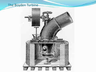
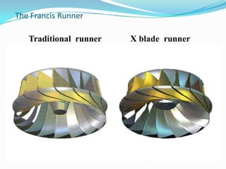
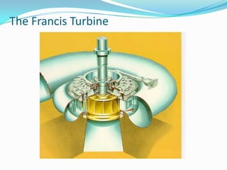
By:
Prathamesh,Akash
Introduction
 A turbine is a rotary mechanical device that
extracts energy from a fluid flow and converts it into
useful work.
 Turbines are used in boat propulsion systems,
hydroelectric power generators, and jet aircraft
engines.
Basic Types of Turbine
 Steam Turbine
 Water Turbine
 Wind Turbine
Types Based Energy Used
 Impulse turbine : Only kinetic energy of water is
used to drive turbine.
Eg.Pelton Turbine
 Reaction turbine : Kinetic energy as well as
Pressure energy of water is used to drive turbine.
Eg.Francis Turbine
Introduction
 Francis turbines are the most common water
turbine in use today.
 They operate in a water head from 10 to 650 meters
(33 to 2,133 feet).
 They are primarily used for electrical power
production.
 The turbine powered generator power output
generally ranges from 10 to 750 megawatts
Sir James B. France
 This turbine was invented by Sir James B.
France in Lowell, Massachusetts, U.S.A.
 Studying the Boyden turbine ,Francis was
able to redesign it to increase efficiency.
 Boyden Turbine could achieve a 65 percent
efficiency.
 So, James France redesigned this turbine
and new turbine with 88% efficiency was
invented.
 This was known as ‘Francis turbine’.
The Boyden Turbine
The Invention
 Studying the Boyden turbine Francis was able to redesign it
to increase efficiency.
 Constructing turbines as “sideways water wheels,” Francis
was able to achieve an astounding 88 percent efficiency
rate.
 After further experimenting, Francis developed the mixed
flow reaction turbine which later became an American
standard.
 Twenty-two of the “Francis turbines” reside in Hoover Dam
to this day.
 His work on these turbines was later published as The
Lowell Hydraulic Experiments in 1855.
X blade runnerTraditional runner
The Francis Runner
The Francis Turbine
The Francis Installation
Working
 Penstock: It is a large size conduit which conveys water from the upstream to the
dam/reservoir to the turbine runner.
 Spiral Casing: It constitutes a closed passage whose cross-sectional area gradually
decreases along the flow direction; area is maximum at inlet and nearly zero at exit.
 Guide Vanes: These vanes direct the water on to the runner at an angle appropriate to the
design, the motion of them is given by means of hand wheel or by a governor.
 Governing Mechanism: It changes the position of the guide blades/vanes to affect a
variation in water flow rate, when the load conditions on the turbine change.
 Runner and Runner Blades: The driving force on the runner is both due to impulse
and reaction effect. The number of runner blades usually varies between 16 to 24.
 Draft Tube: It is gradually expanding tube which discharges water, passing through the
runner to the tail race.
Francis Turbine Power Plant : A Continuous Hydraulic System
Parts of A Francis Turbine
R a d i a l v i e w
runner guide vanes and stay vanes
R a d i a l v i e w
runner guide vanes and stay vanes
R a d i a l v i e w
runner guide vanes and stay vanes
R a d i a l v i e w
runner guide vanes and stay vanes
R a d i a l v i e w
runner guide vanes and stay vanes
R a d i a l v i e w
runner guide vanes and stay vanes
R a d i a l v i e w
runner guide vanes and stay vanes
R a d i a l v i e w
runner guide vanes and stay vanes
R a d i a l v i e w
runner guide vanes and stay vanes
R a d i a l v i e w
runner guide vanes and stay vanes
R a d i a l v i e w
runner guide vanes and stay vanesR a d i a l v i e w
runner guide vanes and stay vanes
Water from
spiral casing
Water particle
Guide vanesGuide vanesGuide vanesGuide vanesGuide vanesGuide vanes
Runner inlet
(Φ 0.870m)
Guide vane outlet for designα)
(Φ 0.913m)
Closed
Position
Max. Opening
Position
Operation of Guide Vanes
Guide vane at Design
Position = 12.21°
Guide vane at closed position
Guide vane at Max. open
Position = 18°
.
Hydraulic efficiency of Francis Hydraulic System
g
V
h
g
V
h
Losseshydraulic
g
V
h
g
V
h
hydraulic
22
22
2
3
3
2
1
1
2
3
3
2
1
1
Advantages
 It is a most widely used turbine in world (about 70-
80%).
 Effective use of water pressure as well as velocity.
 It is American standard turbine.
 Very good efficiency(80-94%).
Disadvantages
 Cost is High.
 Due to its complex design and large number of moving
parts, maintenance and repair is difficult and costly.
 It is applicable to flow of medium head only.
Recent Advancements:
 New types of designs are developed to reduce cost and
complexity of mechanism.
 Modified turbine include Inline Linkless Francis
Turbine, Cross-flow Turbine,etc.
 These new turbine require less space, simplified
designs, less moving parts, etc.
By:
Prathamesh , Akash

Francisturbine

  • 1.
  • 2.
    Introduction  A turbineis a rotary mechanical device that extracts energy from a fluid flow and converts it into useful work.  Turbines are used in boat propulsion systems, hydroelectric power generators, and jet aircraft engines.
  • 3.
    Basic Types ofTurbine  Steam Turbine  Water Turbine  Wind Turbine
  • 4.
    Types Based EnergyUsed  Impulse turbine : Only kinetic energy of water is used to drive turbine. Eg.Pelton Turbine  Reaction turbine : Kinetic energy as well as Pressure energy of water is used to drive turbine. Eg.Francis Turbine
  • 5.
    Introduction  Francis turbinesare the most common water turbine in use today.  They operate in a water head from 10 to 650 meters (33 to 2,133 feet).  They are primarily used for electrical power production.  The turbine powered generator power output generally ranges from 10 to 750 megawatts
  • 6.
    Sir James B.France  This turbine was invented by Sir James B. France in Lowell, Massachusetts, U.S.A.  Studying the Boyden turbine ,Francis was able to redesign it to increase efficiency.  Boyden Turbine could achieve a 65 percent efficiency.  So, James France redesigned this turbine and new turbine with 88% efficiency was invented.  This was known as ‘Francis turbine’.
  • 7.
  • 8.
    The Invention  Studyingthe Boyden turbine Francis was able to redesign it to increase efficiency.  Constructing turbines as “sideways water wheels,” Francis was able to achieve an astounding 88 percent efficiency rate.  After further experimenting, Francis developed the mixed flow reaction turbine which later became an American standard.  Twenty-two of the “Francis turbines” reside in Hoover Dam to this day.  His work on these turbines was later published as The Lowell Hydraulic Experiments in 1855.
  • 9.
    X blade runnerTraditionalrunner The Francis Runner
  • 10.
  • 11.
  • 12.
    Working  Penstock: Itis a large size conduit which conveys water from the upstream to the dam/reservoir to the turbine runner.  Spiral Casing: It constitutes a closed passage whose cross-sectional area gradually decreases along the flow direction; area is maximum at inlet and nearly zero at exit.  Guide Vanes: These vanes direct the water on to the runner at an angle appropriate to the design, the motion of them is given by means of hand wheel or by a governor.  Governing Mechanism: It changes the position of the guide blades/vanes to affect a variation in water flow rate, when the load conditions on the turbine change.  Runner and Runner Blades: The driving force on the runner is both due to impulse and reaction effect. The number of runner blades usually varies between 16 to 24.  Draft Tube: It is gradually expanding tube which discharges water, passing through the runner to the tail race.
  • 13.
    Francis Turbine PowerPlant : A Continuous Hydraulic System
  • 14.
    Parts of AFrancis Turbine
  • 15.
    R a di a l v i e w runner guide vanes and stay vanes R a d i a l v i e w runner guide vanes and stay vanes R a d i a l v i e w runner guide vanes and stay vanes R a d i a l v i e w runner guide vanes and stay vanes R a d i a l v i e w runner guide vanes and stay vanes R a d i a l v i e w runner guide vanes and stay vanes R a d i a l v i e w runner guide vanes and stay vanes R a d i a l v i e w runner guide vanes and stay vanes R a d i a l v i e w runner guide vanes and stay vanes R a d i a l v i e w runner guide vanes and stay vanes R a d i a l v i e w runner guide vanes and stay vanesR a d i a l v i e w runner guide vanes and stay vanes Water from spiral casing Water particle
  • 16.
    Guide vanesGuide vanesGuidevanesGuide vanesGuide vanesGuide vanes Runner inlet (Φ 0.870m) Guide vane outlet for designα) (Φ 0.913m) Closed Position Max. Opening Position
  • 17.
    Operation of GuideVanes Guide vane at Design Position = 12.21° Guide vane at closed position Guide vane at Max. open Position = 18° .
  • 18.
    Hydraulic efficiency ofFrancis Hydraulic System g V h g V h Losseshydraulic g V h g V h hydraulic 22 22 2 3 3 2 1 1 2 3 3 2 1 1
  • 19.
    Advantages  It isa most widely used turbine in world (about 70- 80%).  Effective use of water pressure as well as velocity.  It is American standard turbine.  Very good efficiency(80-94%).
  • 20.
    Disadvantages  Cost isHigh.  Due to its complex design and large number of moving parts, maintenance and repair is difficult and costly.  It is applicable to flow of medium head only.
  • 21.
    Recent Advancements:  Newtypes of designs are developed to reduce cost and complexity of mechanism.  Modified turbine include Inline Linkless Francis Turbine, Cross-flow Turbine,etc.  These new turbine require less space, simplified designs, less moving parts, etc.
  • 22.